A Double ZVS-PWM Active-Clamping Forward Converter ... - Ivo Barbi
A Double ZVS-PWM Active-Clamping Forward Converter ... - Ivo Barbi
A Double ZVS-PWM Active-Clamping Forward Converter ... - Ivo Barbi
- No tags were found...

You also want an ePaper? Increase the reach of your titles
YUMPU automatically turns print PDFs into web optimized ePapers that Google loves.
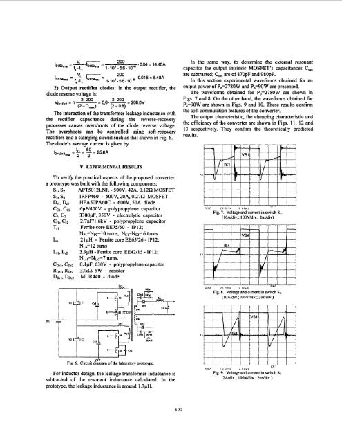
2) Output rectifier diodes: in the output rectifier, thediode reverse voltage is:2.200 2.200v,., = n .-= 0,6 .-= 200.0V(2 D,) (2 0.8)The interaction of the transformer leakage inductance withthe rectifier capacitance during the reverse-recoveryprocesses causes overshoots of the diode reverse voltage.The overshoots can be controlled using soft-recoveryrectifiers and a clamping circuit such as that shown in Fig. 6.The diode's average current is given by50lDrlD,Z,vp = '0 = - = 25.OA2 2In the same way, to determine the external resonantcapacitor the output intrinsic MOSFET's capacitances C,are subtracted; C, are of 870pF and 980pF.In this section experimental waveforms obtained for anoutput power of P0=2780W and P0=90W are presented.The waveforms obtained for P0=2780W are shown inFigs. 7 and 8. On the other hand, the waveforms obtained forP0=90W are shown in Figs. 9 and 10. These results confmthe soft commutation features of the converter.The output characteristic, the clamping characteristic andthe esciency of the converter are shown in Figs. 11, 12 and13 respectively. They confirm the theoretically predictedresults.V. EXPERIMENTAL RESULTSTo verify the practical aspects of the proposed converter,a prototype was built with the following components:Si, S2 APT5012LNR - 500V, 42A, 0.1252 MOSFETs3, s4 JRFP460 - 500V, 20A, 0.27R MOSFETDrl, Dr2 HFA5OPA60C - 600V, 50A diodeCCI, Cc2 6pF/400V - polypropylene capacitorC1, C2 3300pF, 350V - electrolytic capacitorCrl, C,, 2.7nF/1.6kV - polypropylene capacitorTrl Ferrite core EE75/50 - IP12;NpI=Nm=lO turns, Ns~=Ns~= 6 turnsLOL,1, Lr221pH - Ferrite core EE65/26 - IP12;Nh=12 turns3.9pH - Ferrite core EE42/15 - IP12;NLrl=NLR=7 turns.Cwl, Cm 0.1 pF, 630V - polypropylene capacitorRb1, Rm2 33kW 5W - resistorDDrl,DDr2 MUR440 - diodeRef2 20 OmV 200~5Fig. 7. Voltage and current in switch SI.(10Ndiv.; 100V/div.; 2uddiv)Ref2 20 OmV 2 OopsFig. 8. Voltage and current in switch S4.( 1 ONdiv.; 100Vldiv.; 2usldiv.)1VIFig. 6. Circuit diagram of the laboratory prototype.For inductor design, the leakage transformer inductance issubtracted of the resonant inductance calculated. In theprototype, the leakage inductance is around 1.7pH.L,, ,Ref2 io omv 2 oovsFig. 9. Voltage and current in switch SI.2Ndiv.; lOOV/div.; 2uddiv.)600