Ceiling Mounted Work Station and Monorail Manual - Columbus ...
Ceiling Mounted Work Station and Monorail Manual - Columbus ...
Ceiling Mounted Work Station and Monorail Manual - Columbus ...

You also want an ePaper? Increase the reach of your titles
YUMPU automatically turns print PDFs into web optimized ePapers that Google loves.
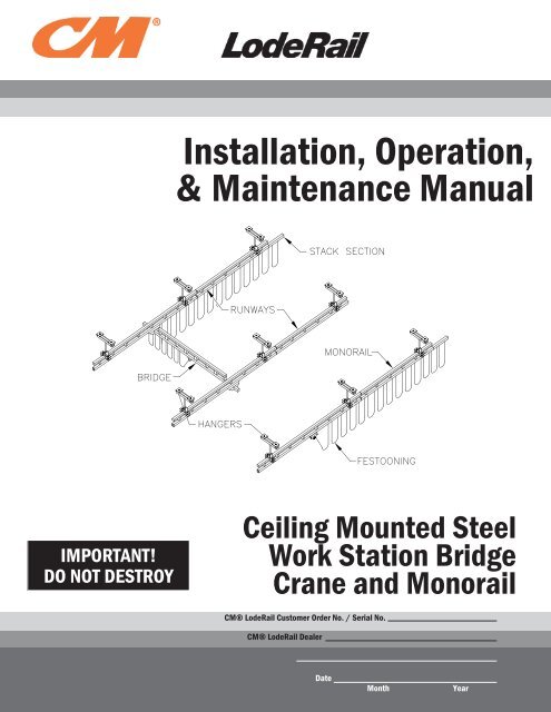
Installation, Operation,& Maintenance <strong>Manual</strong>IMPORTANT!DO NOT DESTROY<strong>Ceiling</strong> <strong>Mounted</strong> Steel<strong>Work</strong> <strong>Station</strong> BridgeCrane <strong>and</strong> <strong>Monorail</strong>CM® LodeRail Customer Order No. / Serial No.CM® LodeRail DealerDateMonthYear
TABLE OF CONTENTSIntroduction................................................................................................................................................1InstallationStep 1 - Pre-assembly...........................................................................................................................1Step 2 - Hanger Installation................................................................................................................2-4Step 3 - Runway Installation...............................................................................................................5-6Step 4 - Splice Joint Installation.............................................................................................................7Step 5 - Bridge <strong>and</strong> End Truck Installation.........................................................................................8-9Step 6 - Hoist Trolley Installation....................................................................................................10-11Step 7 - Festoon Stack Section Installation.........................................................................................12Step 8 - Festooning Installation......................................................................................................13-15Step 9 - Bridge <strong>and</strong> Runway Tagline Installation............................................................................15-16Step 10 - Optional Accessories.......................................................................................................16-17Step 11 - Final Steps...........................................................................................................................17Applied Forces to the Supporting Structure..................................................................................18Sway Bracing <strong>and</strong> Thrust Bracing Guidelines..............................................................................19Crane Operator Instructions...............................................................................................................20General Operational Suggestions....................................................................................................20Limited Warranty...................................................................................................................................21Inspection <strong>and</strong> Maintenance Schedule...........................................................................................22Questions? Concerns? Comments? Please call (800) 888-0985 (US <strong>and</strong> Canada) or(716) 689-5400 (outside US).
INTRODUCTIONThank you for choosing CM® LodeRail <strong>Ceiling</strong> <strong>Mounted</strong> <strong>Work</strong> <strong>Station</strong> Cranes to solve your material h<strong>and</strong>ling needs.The innovative design <strong>and</strong> heavy-duty construction of the CM® LodeRail <strong>Work</strong> <strong>Station</strong> Cranes will provide asuperior quality product that will offer years of long term value. All CM® LodeRail cranes are pre-engineered forpowered hoist operation. The hoist weight allowance is 15% of the crane’s capacity (for example, a crane rated for1000 pounds, allows for a 1000-pound live load plus 150 pounds for the weight of the hoist). There is also anallowance of 25% of the crane capacity for impact caused by hoist use. CM® LodeRail <strong>Work</strong> <strong>Station</strong> Cranes willprovide many years of dependable service by following the installation <strong>and</strong> maintenance procedures describedherein.Dimensions contained in this installation manual are for reference only <strong>and</strong> may differ for your particularapplication. Please refer to the enclosed General Arrangement Drawing for actual dimensions.Normal safety precautions: These include, but are not limited to:• Checking for obstructions in crane travel• Checking that all bolts <strong>and</strong> threaded rods are tight <strong>and</strong> have lockwashers• Making sure that end stops are in place• Making sure that festooning cannot be snagged or pinched, whether it is electric or pneumaticFor additional safety precautions, see page 20.WARNINGEquipment described herein is not designed for, <strong>and</strong> should not be used for, lifting, supporting or transporting humans. Failure tocomply with any one of the limitations noted herein can result in serious bodily injury <strong>and</strong>/or property damage. Check State <strong>and</strong>Local regulations for any additional requirements.WARNINGCrane cannot be utilized as a ground: A separate ground wire is required. For example, systems with 3-phase power requirethree conductors plus one ground wire.WARNINGBefore installing any crane system, it is critical you determine that your building will safely support the loads. CM® LodeRailassumes no responsibility for adequacy or integrity of the mounting surface.WARNINGSway bracing is required (except when using flush mounted hangers). For more information see page 19.WARNINGReference the American Institute of Steel Construction (AISC) <strong>Manual</strong> of Steel Construction (9th edition), Part 5, Specification forStructural Joints using ASTM A325 or A490 Bolts (section 8.d.2) for the proper procedures to follow when using any torquetighteningmethod.INSTALLATIONTIP: Packing list can be found in plastic pocket attached to the hardware box: General Arrangement Drawing<strong>and</strong> additional inserts can be found enclosed in this installation manual.STEP 1 - PRE-ASSEMBLY1.1 Read entire installation manual before you begin installing your crane.1.2 Check packing list to make sure correct quantity of parts is included.1.3 Tools <strong>and</strong> materials typically needed to assemble crane are as follows:. . • H<strong>and</strong> tools. . . • Powered metal-cutting saw. . • Leveling tools.. . • Steel shims (for flush mounted hangers). . • Ladders/man lifts. . • Torque wrench (able to torque up to 200-ft. lb.)1/111
STEP 2 - HANGER INSTALLATIONNOTE: St<strong>and</strong>ard top hanger brackets are designed for flange widthsfrom 1”-3”, 3-1/4”-5-1/4”, 5-1/2”-7-1/2”, 8”-10”.Top Hanger Assemblies2.1 Mark top hanger placement on the building support beams <strong>and</strong>runway/monorail track (refer to the General ArrangementDrawing, inserted in this manual, for hanger placement).Installation parameters can be found on page 18.If you have st<strong>and</strong>ard hangers, go to Step 2.2.If you have sloped hangers, go to Step 2.3.2.2 To attach threaded rod to top hanger bracket:WARNINGThreaded rod must have a minimum of two threads beyond thehexnut.Assemble top hanger assembly (diagram 2A). Refer to Chart 2Afor proper nut torque.Bridge Crane<strong>Monorail</strong>TORQUE CHART*Bolt Diameter Torque1/2” 50 ft.-lb.5/8” 95 ft.-lb.3/4” 150 ft.-lb.Chart 2A. Torque Chart.*Note: All bolts shall be SAEGrade 5 or equal.250-2000#4000#Diagram 2A. Attaching threaded rod to top hanger bracket.Go to Step 2.4, on page 3.2.3 To attach clevis to top hanger bracket:WARNINGSloped ceiling hangers must not be installed on beams more than 15 degrees from horizontal.Assemble top hanger assembly (diagram 2B). Refer to chart 2A for proper but torque.Insert threaded rod into clevis (diagram 2D).250-2000# 4000#Diagram 2B. Attaching clevis to top hanger bracket.Diagram 2C. Installing cotterpin through clevis pin.Bend both legs of all cotter pins (diagram 2C).WARNINGFully bend both legs of cotter pin (diagram 2C). If cotter pin is crackedor fatigued it must be replaced.WARNINGThreaded rod must have a minimum of two threads beyond the clevis.Diagram 2D. Attachingthreaded rod to clevis.21/11
STEP 2 - HANGER INSTALLATION (CONTINUED)2.4 Bolt top hanger bracket assembly <strong>and</strong> beam clips to building support beam (diagram 2E or 2F).Note: Flange thickness may vary <strong>and</strong> require shimming. Shimming may be needed to assure that thebeam clip hardware is vertical.WARNING“Center hole” of the top hanger bracket assembly must be centered on building support beam.250-2000# 4000#Diagram 2E. Bolting st<strong>and</strong>ard top hanger bracket <strong>and</strong> beam clips to existing support beam.250-2000# 4000#Diagram 2F. Bolting sloped top hanger bracket <strong>and</strong> beam clips to existing support beam.Lower Hanger Assemblies2.5 For untrussed (plain) track:WARNINGDo not over-tighten clamping bolts on the lower hanger assemblies: this will cause permanent damage tothe runway track.Slide lower hanger assembly over the runway track <strong>and</strong> bolt into place with clamping bolts (diagram 2G).Note: Install the vertical bolts for beam clips (Step 3.2, on page 5) on the Perpendicular Flush MountHanger 250-2000# (diagram 2G), before sliding it on the track.Plain Track 250-2000# Perpendicular Flush Mount 250-2000# Parallel Flush Mount 250-2000#Plain Track 4000# Perpendicular Flush Mount 4000# Parallel Flush Mount 4000#Diagram 2G. Installing lower hanger assemblies on untrussed (plain) track.1/113
STEP 2 - HANGER INSTALLATION (CONTINUED)For trussed track:WARNINGBolts must have a minimum of two threadsbeyond hexnut.Bolt the lower hanger assembly <strong>and</strong> lower spineclamp plate to the top truss tube of runway(diagram 2H).Tighten nuts until lockwashers are fully compressed.Note: Sway brace brackets should be installed atthis time (see page 19).Perpendicular Flush Mount2.6 For trussed track:WARNINGThreaded rod must have a minimum of two threads beyond hexnut.Trussed Track 250-2000# Trussed Track 4000#Diagram 2H. Bolting lower hanger assembly <strong>and</strong> spineclamp plate to trussed track.Position spine clamp angles (or plates) so they are centered under top tube of runway at hanger locations.Bolt spine clamp angle (or plate) <strong>and</strong> top hanger brackets together leaving maximum amount of threadedrod available above top hanger bracket for installation of beam clips (diagram 2I).WARNING“Center hole” of top hanger brackets should be centered on building support beam but may be offset toprevent vertical interference.Position runway top tube flush <strong>and</strong> perpendicular to building support beam. Bolt top hanger brackets <strong>and</strong>beam clips to support beam. Torque nuts (chart 2A, page 2, for proper torque rating).Note: Flange thickness may vary <strong>and</strong> require shimming. Shimming may be needed to assure that thebeam clip hardware is vertical. Refer to Step 3, on page 5, for further runway installation instructions.Trussed track with 1-1/2” to 2-1/2” top tube.Trussed track with 3” to 6” top tube.Diagram 2I. Installing Perpendicular Flush <strong>Mounted</strong> Hangers on trussed track.4 1/11
STEP 3 - RUNWAY INSTALLATIONNOTE: The closer the runways/monorails are to level <strong>and</strong> parallel,the better the crane will perform.NOTE: Track running-surface misalignment at joints shall beadjusted to within 1/32” (1mm) when installed.Bridge Crane3.1 Lift the runway/monorail into place for installation.3.2 HangersWARNINGThreaded rod must have a minimum of two threads beyond thehexnut.<strong>Monorail</strong>WARNINGThreaded rod must be allowed to hang “plumb” <strong>and</strong> should not bebent to accommodate sloped ceilings.For st<strong>and</strong>ard <strong>and</strong> sloped ceiling hangerswith threaded rod drop:Insert threaded rod into bolt hole on thelower hanger assembly <strong>and</strong> bolt into place(diagram 3A).Torque nuts (chart 2A, page 2, for propertorque rating).For flush mounted st<strong>and</strong>ard hangers:Bolt flush mounted hanger <strong>and</strong> beam clips tobuilding support beam (diagram 3B).Torque nuts (chart 2A, page 2, for propertorque rating).For flush mounted sloped ceiling hangers:Insert bolt, with lockwasher, into bolt hole onthe lower hanger assembly <strong>and</strong> fasten to clevis(diagram 3C).Torque hardware (chart 2A, page 2, for propertorque rating).WARNINGBolt must have a minimum of two threadsbeyond the clevis.Untrussed (Plain) TrackTrussed TrackDiagram 3A. Attaching lower hanger assembly to top hangerassembly.Parallel Flush <strong>Mounted</strong>Perpendicular Flush <strong>Mounted</strong>Diagram 3B. Attaching flush mounted hangers to buildingsupport beam.250-2000# 4000#Diagram 3C. Attaching flush mounted sloped ceiling hangers to tophanger assembly.1/115
STEP 3 - RUNWAY INSTALLATION (CONTINUED)For sloped ceiling hangers:Beam clips must be welded to support beam to prevent clips from shifting (diagram 3D).For 3-hole hangers:Diagram 3D. Welding beam clips to support beams.WARNINGDo not deviate from the dimensions specified in the General Arrangement Drawing for themaximum spacing of the runway hangers.Insert threaded rod into bolt on the lower hanger assembly <strong>and</strong> through the pre-drilled holes in the runwaytop tube (diagram 3E).Torque nuts (chart 2A, page 2, for proper torque rating).IMPORTANT: Note the placement of the threaded rod hardware in diagram 3E. The lower hangerassembly <strong>and</strong> the truss top tube must be properly clamped to provide adequate support.3.3 Level track:Check to make sure that the lower flange of track is level <strong>and</strong> parallel to opposite runway (within +/-1/32”) atjoints.3.4 If you do have additional runways/monorail sections proceed to Step 4, on page 7.If you do not have additional runways/monorail sections:Install end stops (diagram 3F) (molded bumper with thru bolt), in runwayend opposite festooning end. For more information on festooning, refer toStep 8, on page 13.Tighten nut on thru bolt until lockwasher is flat.Diagram 3E. 3-Hole Hanger, 250#-2000#.WARNINGDo not deviate from the bridge “span” dimension shown on the General Arrangement drawing. Bridge“span” is the distance between runways (centerline to centerline).If you have a bridge crane, go to Step 5, on page 8.If you have a monorail, go to Step 6, on page 10.Diagram 3F. Installing end stop.6 1/11
STEP 4 - SPLICE JOINT INSTALLATIONIMPORTANT: If using trussed track, use both the splice joint <strong>and</strong> thesplice plate.IMPORTANT: Suitable splices shall be provided at all track joints.Bridge CraneWARNINGDo not deviate from the dimensions specified in the General ArrangementDrawing for maximum space from hanger point to splice joint. Installationparameters can be found on page 18.4.1 Attach hardware to splice joint. Slide splice joint over track of installedrunway/monorail.4.2 The maximum gap between ends of the load carrying flange shall not exceed1/16” (1.5mm).4.3 Slide next runway/monorail section into splice joint, bringing runway/monorailends as close as possible (diagram 4A or 4B).Center the splice joint over the track ends.4.4 For trussed track: Place a truss splice plate on each side of runway trusstube <strong>and</strong> bolt into place (diagram 4B). Tighten hexnuts, but do not torqueuntil you have completed Steps 4.4 <strong>and</strong> 4.5.4.5 Refer to Step 2.5, on pages 3 <strong>and</strong> 4, for lower hanger installation. Attach runway to upper hanger byrepeating Steps 3.2, on page 5 <strong>and</strong> 3.4, on page 6.4.6 Adjust track for smooth transition:<strong>Monorail</strong>Diagram 4A. Splicinguntrussed track.WARNINGDo not “over-tighten” clamping bolts on splice joints: this will cause permanent damage to the runwaytrack. Clamping bolts are utilized for alignment purposes.Tighten clamping bolts along the top of splice joint to force trackdown onto lower flanges of splice. Check to see that the transitionfrom one track to the other is smooth: no raised areas to inhibittrolley or end truck operation.Tighten clamping bolts along the sides of splice joint to align tracklaterally. Check to see that track portion of runway/monorail ishorizontally <strong>and</strong> vertically flush.Tighten jam nuts, on both the top <strong>and</strong> sides of the splice joint, to lockclamping bolts in place (diagram 4A or 4B).4.7 For trussed track: After you have adjusted the track for smoothtransition, torque the truss splice plate hexnuts (chart 2A, on page 2).4.8 For additional runways repeat Steps 4.1 through 4.6.4.9 Install end stops (Step 3.4, on page 6).Diagram 4B. Splicing trussed track.1/117
STEP 5 - BRIDGE AND END TRUCK INSTALLATIONIMPORTANT: ONLY ONE end truck is clamped to the bridge: the other isnot. The clamping end truck must be oriented with the festooning side ofthe track (refer to Step 8, on page 13 for festooning). The non-clampingend truck allows adjustment for any runway misalignment.IMPORTANT: Extended end truck should be assembled before attachingto bridge.Bridge Crane5.1 Make sure end stops have been installed in the runway end oppositethe festooning (leaving festooning end open for bridge installation).5.2 Prior to adding bridge, clean inside flanges of track with clean, drycloth (do not use any kind of cleaning solution) to remove grit ordebris that may have collected during shipping, storage, or installation.5.3 If your end trucks look like:(Shipped Assembled)go to Step 5.4(Shipped Unassembled)go to Step 5.7St<strong>and</strong>ard End Trucks5.4 Slide an end truck over festooning end of bridge (refer to theGeneral Arrangement Drawing for exact end truck location, endtruck sleeve must be 1” (+/- 1/4”) from first vertical) <strong>and</strong> clamp intoplace with hardware provided (diagram 5A).Note: The festooning end of the bridge will have a hole that isinset the same or greater distance from the end of the bridge thanthe hole in the opposite end of the bridge.5.5 Slide <strong>and</strong> position the non-clamping end truck on the other end ofbridge (refer to the General Arrangement Drawing for exactlocation, end truck sleeve must be 1” (+/- 1/4”) from first vertical).5.6 Go to Step 5.16, on page 9.Extended End Trucks5.7 Locate extended end truck tubes, support weldment, wheel plates,<strong>and</strong> required hardware.5.8 Slide an extended end truck tube halfway through each side of theend truck support weldment (diagram 5B). Insert a support bolt ineach hole of the support weldment.5.9 Place nylock nut on end of each bolt <strong>and</strong> tighten snug against endtruck support weldment.Diagram 5A. Installing st<strong>and</strong>ard clampingend truck. See NOTE.SUPPORT BOLTEXTENDED ENDTRUCK TUBESEXTENDED END TRUCKSUPPORT WELDMENTNYLOCK NUTDiagram 5B. Assembling extendedend truck.WARNINGDo not “over-tighten” nylock nut; this could cause damage to end trucks.Nylock nut can only be used once. If this item is disassembled, then nutmust be replaced.8 1/11
STEP 5 - BRIDGE AND END TRUCK INSTALLATION (CONTINUED)IMPORTANT: ONLY ONE end truck is clamped to the bridge: the other is not. The clamping end truck must beoriented with the festooning side of the track (refer to Step 8, on page 16 for festooning). The non-clamping endtruck allows adjustment for any runway misalignment.IMPORTANT: Extended end truck should be assembled before attaching to bridge.Extended End Trucks (continued)5.10 Place a wheel plate between the end truck tubes. Insert 5/8” dia. bolt into firsttube, through the wheel plate <strong>and</strong> out the opposite tube (diagram 5C).5.11 Place nylock nut on end of bolt <strong>and</strong> tighten snug againstextended end truck tube. Note: When tightening this lock nutmake sure that wheel plate pivots freely.WARNINGDo not “over-tighten” nylock nut; this could cause damage toend trucks. Nylock nut can only be used once. If this item isdisassembled, then nut must be replaced.EXTENDED ENDTRUCK TUBESWHEEL PLATENYLOCK NUT5.12 Repeat steps 5.10 <strong>and</strong> 5.11 for remaining wheel plate.5.13 Repeat steps 5.7 to 5.12 for remaining extended end trucks.5.14 Slide an end truck over festooning end of bridge (refer to theGeneral Arrangement Drawing for exact end truck location,end truck sleeve must be 1” (+/- 1/4”) from first vertical) <strong>and</strong>clamp into place (diagram 5D).Note: The festooning end of the bridge will have a hole that isinset the same or greater distance from the end of the bridgethan the hole in the opposite end of the bridge.5.15 Slide <strong>and</strong> position the non-clamping end truck on the other endof bridge (refer to the General Arrangement Drawing for exactlocation, end truck sleeve must be 1” (+/- 1/4”) from first vertical).5.16 Install an end stop to the end of the bridge opposite the festooning(diagrams 5E or 5F).5.17 Lift bridge up to runways <strong>and</strong> simultaneously insert end trucks into openends of runways. Make sure festooning end of bridge is oriented withfestooning runway. For information on festooning, refer to Step 8, onpage 13.5.18 Immediately install end stops in open ends of runways to preventbridge from exiting runways (diagrams 5E or 5F).5.19 Roll bridge down length of runways to check for smooth travel. Iftravel is not smooth, check track for level <strong>and</strong> parallel (Step 3.4, page6) <strong>and</strong> check to make sure that only one end truck on bridge isclamped.5/8” BOLTDiagram 5C. Installing wheel plates.BRIDGE WELDMENTEXTENDED ENDTRUCKDiagram 5D. Installing extendedclamping end truck. See NOTE.Diagram 5E. Installing end stop.Diagram 5F. Installing end stop.1/119
STEP 6 - HOIST TROLLEY INSTALLATIONBridge Crane6.1 If your hoist trolley looks like:(shipped assembled)go to Step 6.2250#, 500#, 1000# <strong>and</strong> 2000# Hoist Trolley(shipped assembled)go to Step 6.156.2 Clean inside flanges of track with a clean, dry cloth (do not use any kind of cleaning solution) to removegrit or debris that may have collected during shipping, storage, or installation.6.3 Be sure end stop is installed opposite the festooning end of bridge/monorail.6.4 Attach hoist to hoist trolley by snapping hoist suspension hook over the trolley saddle clevis pin of hoisttrolley.<strong>Monorail</strong>6.5 If hoist suspension is too large or hoist has a suspension device other than a hook, remove trolley saddleclevis pin <strong>and</strong> install suspension device (by others). Insert clevis pin back into place. Slide washers onclevis pin <strong>and</strong> insert cotter pin through trolley saddle clevis pin (diagrams 6A, 6B, <strong>and</strong> 6C).Diagram 6A. Installing hoist on250# hoist trolley.Diagram 6B. Installing hoist on500# hoist trolley.Diagram 6C. Installing hoist on1000-2000# hoist trolley.6.6 Bend back both legs of cotter pin (diagram 6D).WARNINGFully bend both legs of cotter pin (diagram 6D). If cotter pin is cracked or fatigued it must be replaced.6.7 If a tow arm is not being utilized on the trolley, go to Step 6.12, on page 11.If a tow arm is being utilized on the trolley, go to Step 6.8.Note: Festoon tow arms are not recommended for use on 4000# systems orsystems with extended end trucks. They are not necessary for systems withfestoon trolleys.6.8 Remove wheels from festoon end of trolley (as needed). Keep snap rings.6.9 Assemble the tow arm weldment on the festooning end of thehoist trolley (diagram 6E).6.10 Re-assemble wheels <strong>and</strong> snap rings (as needed).6.11 After the hoist trolley has been installed, loosen nuts on end ofU-bolt enough to thread cable/air hose between the two legs ofthe U-bolt <strong>and</strong> festoon clamp plate. Secure cable/air hose bytightening nuts at the end of the U-bolt, forcing the festooningclamp plate snug against the cable/air hose.Diagram 6D. Installingcotter pin through trolleysaddle clevis pin.Diagram 6E. Installing tow arm on trolley.10 1/11
STEP 6 - HOIST TROLLEY INSTALLATION (CONTINUED)6.12 Roll hoist trolley into open end of track on bridge/monorail.6.13 Install end stop on the festooning end of bridge/monorail (diagram 3F, on page 6).6.14 If you have tagline, go to Step 9, on page 15.If you do not have festooning, go to Step 11, on page 17.If you do not have a festoon stack section, go to Step 8, on page 13.Otherwise go to Step 7, on page 12.Loadbar Hoist Trolley 4000#6.15 Clean inside flanges of track with a clean, dry cloth (do not use any kind ofcleaning solution) to remove grit or debris that may have collected duringshipping, storage, or installation.6.16 Be sure end stop is installed opposite the festooning end of bridge/monorail.6.17 Bend both legs of all cotter pins (diagram 6F).Diagram 6F. Installingcotter pin through trolleysaddle clevis pin.WARNINGFully bend both legs of cotter pin (diagram 6F). If cotter pin is cracked or fatigued it must be replaced.6.18 Attach hoist to hoist trolley by snapping hoist suspension hook over the clevis bolt (center bolt) on hoisttrolley loadbar.WARNINGHang hoist from clevis bolt (center bolt) of hoist trolley only.6.19 If hoist suspension hook is too large or hoist has a suspension device other than a hook, you will need toremove clevis bolt <strong>and</strong> install suspension device (by others). Insert clevis bolt back into place. Place nylocknut on end of bolt <strong>and</strong> tighten (diagram 6G).WARNINGBe sure to tighten nut on the clevis bolt (center bolt) of hoist trolley. Do not “over-tighten” nylock nut:could cause damage to trolleys. Nylock nut on clevis bolt should only be used once. If this item isdisassembled, then nut must be replaced.Diagram 6G. Installing hoist on loadbar hoist trolley.6.20 Roll hoist trolley into open end of track on bridge/monorail.6.21 Install end stop on festooning end of bridge/monorail (diagram 3F, on page 6).6.22 If you have tagline, go to Step 9, on page 15.If you do not have festooning, go to Step 11, on page 17.If you do not have a festoon stack section, go to Step 8, on page 13.Otherwise go to Step 7, on page 12.1/1111
STEP 7 - FESTOON STACK SECTION INSTALLATIONTIP: Festoon stack section allows festooning to stack up at the end ofthe system, permitting full use of runway/monorail.7.1 Remove end stop on festooning end of runway/monorail.For All Systems With Festoon Gliders, or Systems With FestoonTrolleys <strong>and</strong> 1000, 2000, or 4000 Series Track (diagram 7A)Bridge CraneFestoon Glider7.2 Slide festoon stack section over open runway/monorail end.7.3 Re-install end stop (diagram 7A).7.4 Use leveling screws located at top of festoon stacksection to align it with the runway/monorail.For Systems With Festoon Trolleys <strong>and</strong> 250 or 500Series Track (diagram 7B)Note: Welding is required to attach festoon stack section to runway/monorail when using festoon trolleyswith 250 or 500 series track.7.5 Slide festoon stack section over open runway/monorail end.7.6 Use leveling screws located at top of festoon stack section to align it with runway/monorail.7.7 Weld festoon stack section to runway/monorail at locations (diagram 7B).Note: Because trolleys are too large to roll under the end stop on the 250 <strong>and</strong> 500 series track, the endstop <strong>and</strong> accompanying hardware (which held the festoon stack section to the runway/monorail) ispositioned at the end of the festoon stacksection. To prevent festoon stack sectionfrom sliding off the runway/monorail, thefestoon stack section is welded.7.8 Install end stop (removed in step 7.1) in endof festoon stack section (diagram 7B).Festoon TrolleyDiagram 7A. Installing festoon stack section.WARNINGDo not “over tighten” leveling screws: this will cause permanent damage to the track.WARNINGAll welds must meet American Welding Society (AWS) specification D1.1 using E70xx electrodes.<strong>Monorail</strong>Diagram 7B. Welding festoon stack section on 250-500# seriestrack.12 1/11
STEP 8 - FESTOONING INSTALLATIONTIP: Festoon gliders are comprised of a glider body (with upper saddle)<strong>and</strong> lower saddle (a separate piece that clips onto the glider body).TIP: Enough carriers (festoon gliders or festoon trolleys are supplied tosupport festoon conductor every 6’ on runway/monorail <strong>and</strong> every3’ on bridges.Note: Every 6’ on vacuum hose trolley.Bridge Crane8.1 If you are using:<strong>Monorail</strong>festoon gliders, go to Step 8.2 festoon trolleys, go to Step 8.7Festoon GlidersIf you have a monorail go to Step 8.4.8.2 Slide festoon gliders through end of bridge that corresponds withfestooning on runway. Space festoon gliders every 3’-0” along bridge.8.3 Slide festoon clamp into place at festooning end of bridge <strong>and</strong> tightenclamp bolt (diagram 8A).8.4 Slide festoon gliders into festoon stack section end of runway/monorail track (on festooning side of runway/monorail). Spacefestoon gliders every 6’-0” along runway/monorail, between bridge<strong>and</strong> festoon stack section.8.5 Slide festoon clamp into end of runway/monorail/festoon stack section (diagram 8A). Tighten clamp boltuntil lockwasher is flat.8.6 Proceed to Step 8.15, on page 14.Festoon TrolleysDiagram 8A. Installing festoon clampon runway or bridge.IMPORTANT: Before installing festoon trolleys in 250 <strong>and</strong> 500 series track, the molded bumper (onfestooning end of bridge runway) must first be removed.If you have a monorail go to Step 8.11, on page 14.8.7 For 250-500 series track:Remove end stop on festooning end of bridge.8.8 Roll festoon trolleys through open end of bridge thatcorresponds with festooning on runway. Space festoontrolleys every 3’-0” along bridge.Note: Every 6’-0” for vacuum hose festooning.8.9 Slide festoon clamp/vacuum hose clamp into place atfestooning end of bridge <strong>and</strong> tighten clamp bolt (diagrams8A or 8B).8.10 Re-install end stop (molded bumper with through bolt) infestooning end of bridge (diagram 8C, page 14).Diagram 8B. Installing vacuum hose clamp onrunway or bridge.1/1113
STEP 8 - FESTOONING INSTALLATION (CONTINUED)IMPORTANT: Before installing festoon trolleys in 250 <strong>and</strong> 500 series track, the molded bumper (on festooningend of bridge runway) must first be removed.8.11 For 250-500 series track:Remove end stop from festoon stack section/festooning end of runway/monorail.8.12 Roll festoon trolleys into end of runway/monorail/festoon stack sectiontrack (on festooning side of runway/monorail). Space festoon trolleysevery 6’0” along runway/monorail, between bridge <strong>and</strong> festoon stacksection.8.13 Slide festoon clamp into end of runway/monorail/festoon stack section <strong>and</strong>tighten clamp bolt (diagram 8A or 8B, on page 13).8.14 For 250 or 500 series track:Re-install end stop in runway/monorail/festoon stack section (diagram 8C).8.15 Installing Festoon Electric Cable/Air Hose/Vacuum Hose:Gliders are designed to accept 4-conductor, electric flat cable (#12 or #14 gauge). Festoon trolleys aredesigned to accept 4-conductor, electric flat or round cable (#12 or #14 gauge) or air hose (maximum: 7/8”outside diameter).Electric Cable with Festoon GlidersThread electric cable between upper <strong>and</strong> lowersaddles of glider. Secure electric cable by pushinglower saddle up glider legs, clamping electric cableinto place (diagram 8D).Diagram 8C. Installing end stopon runway/monorail/festoonstack section.WARNINGCrane cannot be utilized as a ground: A separate ground wire is required. For example, systems with3-phase power require 3 conductors plus one ground wire.Electric Cable/Air Hose with Festoon TrolleysLoosen nuts <strong>and</strong> clamp-plate enough to threadelectric cable/air hose between the U-bolt legs <strong>and</strong>clamp plate on festoon trolley. Secure cable bytightening nuts on festoon trolley, forcing clamp platesnug against electric cable/air hose (diagram 8E).Diagram 8D. Installing electric cable on festoon glider.Note:Note:Be careful not to tighten nuts too tight; will cause damage toelectric cable/air hose.Be sure that U-bolt does not interfere with trolley body.IMPORTANT: Cable/Air Hose Installation: It is important that asmuch twist as possible be taken out of the hose before it is hung. Totake the twist out follow the steps below:1. Lay the cable or hose out on the floor flat.Diagram 8E. Installing electric cable or airhose on festoon trolley.2. Mark the cable or hose where the first end clamp will be <strong>and</strong> then make marks for trolley <strong>and</strong> bridgeend clamp locations at 6-7 foot intervals. If cable or hose twist still exists, increase intervals.3. Recoil the cable or hose so that the marks are all lined up on the top of the coiled cable or hose.4. Lay the large coil on the floor with the marks lined up. At each mark, attach a trolley or end clamp.When installing the festoon, pick up the whole coil <strong>and</strong> run the trolleys in without disturbing the coil.Suggestion: Air Swivels should be used at either end of cable or hose to reduce twist.14 1/11
STEP 8 - FESTOONING INSTALLATION (CONTINUED)Vacuum Hose TrolleysPlace strap around vacuum hose (by others). Secure Velcro sidestogether <strong>and</strong> be sure vacuum hose is held snugly in place (diagram 8F).Note:Note:Strap will fit vacuum hoses with outside diameters ranging from 1-1/2” to2-3/4”.Clip vacuum hose hook (with vacuum hose attached) onto vacuum hosetrolley (diagram 8F).If Velcro strap does not hold vacuum hose securely, engage vacuumdevice so a vacuum is present in the hose <strong>and</strong> retighten Velcro straps sothe vacuum hose is held tightly.Diagram 8F. Installing vacuumhose on vacuum hose trolley.STEP 9 - BRIDGE AND RUNWAY TAGLINE INSTALLATION9.1 Slide tagline brackets onto each end of bridge (diagram 9A). Attach tagline mounting angles to vertical tubeusing hardware provided (diagram 9B).Note: This will require removal of endstop hardware. This hardware must be re-installed immediately aftertagline bracket is installed.Diagram 9A. Tagline on bridge.Diagram 9B. Tagline on runway.Diagram 9C. Tagline cable assembly.1/1115
STEP 9 - BRIDGE AND RUNWAY TAGLINE INSTALLATION (CONTINUED)9.2 Attach eyebolts onto tagline brackets. Attach turnbuckle to oneeyebolt. Loop cable through eyebolt or turnbuckle <strong>and</strong> turn back 4-3/4”of cable on a thimble. Apply first clamp 1” from the dead end of thecable <strong>and</strong> tighten U-bolt to 15 ft.-lbs. or torque. Apply the secondclamp as close to thimble as possible. Tighten U-bolt to 15 ft.-lbs. oftorque (diagram 9D).9.3 Add any S-hooks, wire rope trolleys, or coiled air hose to the cableprior to attaching the other end.9.4 Secure other end of the cable as in Step 9.2.Diagram 9D. Saddling the cable onone end.STEP 10 - OPTIONAL ACCESSORIESSafety Cable InstallationA) The safety cable is provided as a single piece <strong>and</strong> must be cut in the fieldas necessary. Each connection requires 5 ft. of cable.B) After cutting the cable down to required length, one end of each cablemust be properly saddled using the thimble <strong>and</strong> U-bolt cable clampsprovided (diagram 10A).C) Turn back 4-3/4” of cable on a thimble or loop. Apply the first clamp 1”from the dead end of the cable <strong>and</strong> tighten U-bolt to 15 ft.-lbs. of torque.Apply the second clamp as close to thimble or loop as possible. TightenU-bolt to 15 ft.-lbs. of torque (diagram 10A).D) Pass the free end of cable through support points of each connection inwhich safety cabling is required.Diagram 10A. Saddling the cable onone end.E) After the free end of cable has passed through all required support points, it should be passed through thesaddled end of cable.F) Saddle the free end of cable while making sure both ends are interlocked. Complete the connection using theinstructions from Step C above (diagram 10B).Diagram 10B. Safety cable installed on ceilingmounted hanger connection.Diagram 10C. Safety cable installed on CM® LodeRailtrolley that will attach to hoist (by others).WARNINGThe cable <strong>and</strong> termination should be inspected periodically for wear, abuse, <strong>and</strong> general adequacy.16 1/11
STEP 10 - OPTIONAL ACCESSORIES (CONTINUED)Coiled Air Hose InstallationA) Assemble female fittings to the coiled air hose according to diagram 10D.The coiled air hose is inserted through the spring guard, nut, ferrule, <strong>and</strong> overthe tube insert as far as possible. Note the orientation of the ferrule: the bevelis pointing towards the female fitting.B) Assemble the remainder of the components per diagram 10E.Diagram 10D. Female fittingassembly.Diagram 10E. Coiled air hose assembly.Double Wired Endstop InstallationA) Install end stop bumper with hardware provided (diagram 10F).B) Install additional hardware with bolt facing the same direction as the end stophardware.C) Insert safety wire through the holes in each end stop bolt <strong>and</strong> twist endstogether to secure wire in place (diagram 10G).Diagram 10F. Installing endstop.STEP 11 - FINAL STEPS11.1 Check to make sure all bolts are tightened to specifications <strong>and</strong> lockwashers are flat.11.2 Be sure to sway brace the crane, except when using flush mounted hangers.11.3 If necessary, touch up crane with paint provided.Diagram 10G. Double wired end stop.WARNINGEnd stop bumper must be placed on the “inside” bolt so that the endtruck or trolley contacts the bumper <strong>and</strong> not thesecondary bolt.TIP: Do not throw away this manual: the maintenance schedule is on the back cover.11.4 Install yellow rubber tracdoms on open ends of steel track.11.5 Keep Packing List, Installation <strong>Manual</strong>, General Arrangement Drawing, <strong>and</strong> any other inserts filed togetherin a safe place.1/1117
INSTALLATION PARAMETERS AND APPLIED FORCES TO THESUPPORTING STRUCTUREThe applied forces drawing in diagram 1, details the relativeposition <strong>and</strong> the direction of forces that the work stationbridge crane applies to the supporting structure.Loads applied to the support structure can be determined bythe following formulas:P = Live LoadR1 = Vertical Load applied by support hanger (lb.)R2 = Longitudinal load applied by movement of the. . crane to each runway (lb.)R3 = Lateral load applied by movement of the trolley <strong>and</strong>. . load to each runway (lb.)L1 = Maximum distance between hanger centerlines. . (support centers) (ft)L2 = Maximum splice joint centerline to hanger. . centerline (support center) (in)L5 = Maximum bridge. . cantilever (in)L9 = Maximum runway. . cantilever (in)L4 = Bridge span (distanceCAPACITY. . between runway. . centerlines) (ft)250#1.4 = Design factor which. . includes 25% for impact. . <strong>and</strong> 15% for hoist weightW = Weight per foot of runway500#. . (lb./ft)w = Weight per foot of bridge. . (lb./ft)1000#Note: If there are only 2 hangersper runway substitute “(L1)/2” for“L1” in the R1 formula.Note: For bridge lengths greaterthan 23 ft., up to 28 ft., use GLCSLweights. Greater than 28 ft.lengths, up to 34 ft., use GLCSLXweights.R1 = (1.4 * P) + (W * L1) + (w * L4). . . . ........2R2 = (1.15 * P) + [(w * L4) * 0.10]. . . .......2R3 = 1.15 * P * 0.202000#4000#Diagram 1. Applied forces to supporting structure.INSTALLATION PARAMETERSSERIESGLCGLCSGLCSLGLCGLCSGLCSLGLCSLXGLCGLCSGLCSLGLCSLXGLCGLCSGLCSLGLCSLXGLCGLCSGLCSLGLCSLXWEIGHTPER FOOT2.55#4.88#8.14#4.11#7.23#10.94#11.26#6.50#12.09#13.37#15.31#9.00#14.59#20.14#20.95#9.00#18.42#23.83#28.02#MAX.L16’20’25’6’20’25’30’6’20’25’30’6’20’25’30’6’20’25’30’MAX.L28”48”48”8”48”48”48”8”48”48”48”8”48”48”48”8”48”48”48”MAX.L518”18”18”24”24”24”24”24”24”24”24”24”24”24”24”24”24”24”24”MAX.L918”48”48”20”48”48”48”20”48”48”48”24”48”48”48”24”48”48”48”18 1/11
SWAY AND THRUST BRACING GUIDELINESTIP: Sway bracing is not required on systems with flush mounted hangers.WARNINGBracing must be installed to resist damaging lateral <strong>and</strong> longitudinal loads.Sway bracing must be located at or near each support location. It isrequired that each sway brace point shall not exceed the smaller of 10% ofthe spacing between supports or 24 inches from a support point. Maximumspacing shall not exceed 30 feet or as determined by structural analysisinvolving maximum unbraced length of the compression flange, <strong>and</strong> thehorizontal length <strong>and</strong> horizontal deflection limit of the track.Thrust bracing must be located at or near end hanger locations. It isrequired that each thrust brace point shall not exceed the smaller of the10% of the spacing between supports or 24 inches from a support point. Ata minimum, there should be two thrust braces per enclosed track runway.At curved locations (used with monorails) bracing shall be provided at ends<strong>and</strong> midpoint of curves, but the maximum spacing shall not exceed threefeet. On monorail systems, track switches shall be braced in bothdirections.Sway or thrust bracing must not be directly attached to hanger rods. Allnew bracing connecting to the flange of the track <strong>and</strong> flanges ofbuilding beams shall use sway brackets or equal as shown in diagram1. When attaching bracing to steel truss or steel beams, the bracingmember shall be attached to the top chord or top flange <strong>and</strong> located asclose to the bridging members as possible.Angle of bracing from vertical preferably should be equal to or greaterthan 45 degrees, but in no case be less than 30 degrees.Generally, bracing is placed either parallel or perpendicular to track.However, skewed bracing is also permissible to accommodate difficultconnections, such as the presence of ducts or pipes. Design of skewedbracing should use the same criteria for parallel/perpendicular bracing.For skewed thrust bracing, two pieces, symmetrical to the track, shouldbe used if the skewed angle is greater than 10 degrees.Size1” Ø pipe SCH 401” Ø pipe SCH 80L 2” x 2” x 1/4”L 2 1/2” x 2 1/2” x 1/4”L 3” x 3” x 1/4”ANGLE AND PIPE BRACE TYPESBased on (KL/r = 300) Design CriteriaArea(in 2 )0.490.640.941.191.44r(in)0.4210.4070.6090.7690.930Max. Length(ft)10.510.179.7512.2814.80Allowable Force(kips)0.811.061.561.982.39K = Effective Length Factor for a Prismatic Member (see AISC manual)L = Length of Bracer = Radius of GyrationDiagram 1. Typical Connection detail.1/1119
CRANE OPERATOR INSTRUCTIONSOverhead cranes <strong>and</strong> jib cranes generally h<strong>and</strong>le materials over working areas where there are personnel. Therefore, it is important for the Crane Operator to beinstructed in the use of the crane <strong>and</strong> to underst<strong>and</strong> the severe consequences of careless operation. It is not intended that these suggestions take precedence overexisting plant safety rules <strong>and</strong> regulations or OSHA regulations. However, a thorough study of the following information should provide a better underst<strong>and</strong>ing of safeoperation <strong>and</strong> afford a greater margin of safety for people <strong>and</strong> machinery on the plant floor. It must be recognized that these are suggestions for the Crane Operator’suse. It is the responsibility of the owner to make personnel aware of all federal, state <strong>and</strong> local rules <strong>and</strong> codes, <strong>and</strong> to make certain operators are properly trained.QualificationsCrane operation, to be safe <strong>and</strong> efficient, requires skill: the exercise of extreme care <strong>and</strong> good judgment, alertness <strong>and</strong> concentration, <strong>and</strong> rigid adherence to provensafety rules <strong>and</strong> practices as outlined in applicable <strong>and</strong> current ANSI <strong>and</strong> OSHA safety st<strong>and</strong>ards. In general practice, no person should be permitted to operate acrane:• Who cannot speak the appropriate language or read <strong>and</strong> underst<strong>and</strong> the printed instructions.• Who is not of legal age to operate this type of equipment.• Whose hearing or eyesight is impaired (unless suitably corrected with good depth perception).• Who may be suffering from heart or other ailments which might interfere with the operator’s safe performance.• Unless the operator has carefully read <strong>and</strong> studied this operation manual.• Unless the operator has been properly instructed.• Unless the operator has demonstrated his instructions through practical operation.• Unless the operator is familiar with hitching equipment <strong>and</strong> safe hitching equipment practices.H<strong>and</strong>ling the Bridge Travel MotionBefore using the bridge of the crane, the operator should be sure the hook is high enough to clear any obstruction. Before a load is h<strong>and</strong>led by the crane, the bridgeshould be brought into position so that it is directly over the load. Start the bridge slowly <strong>and</strong> bring it up to speed gradually. Approaching the place where it is desiredto stop the bridge, reduce the bridge speed.H<strong>and</strong>ling the Trolley MotionBefore a load is h<strong>and</strong>led, the hoist should be positioned directly over the load that is to be h<strong>and</strong>led. When the slack is taken out of the slings, if the hoist is not directlyover the load, bring it directly over the load before hoisting is continued. Failure to center the hoist over the load may cause the load to swing upon lifting. Alwaysstart the trolley motion slowly <strong>and</strong> reduce the trolley speed gradually.H<strong>and</strong>ling the Hoist MotionRefer to the lifting (hoist) equipment’s operating instructions.GENERAL SUGGESTIONSKnow Your CraneCrane operators should be familiar with the principal parts of a crane <strong>and</strong> have a thorough knowledge of crane control functions <strong>and</strong> movements. The crane operatorshould be required to know the location <strong>and</strong> proper operation of the main conductor disconnecting means for all power to the attachments on the crane.ResponsibilityEach crane operator should be held directly responsible for the safe operation of the crane. Whenever there is any doubt as to SAFETY, the crane operator shouldstop the crane <strong>and</strong> refuse to h<strong>and</strong>le loads until: (1) safety has been assured or (2) the operator has been ordered to proceed by the supervisor, who then assumes allresponsibility for the SAFETY of the lift.Do not permit ANYONE to ride on the hook or a load.InspectionTest the crane movement <strong>and</strong> any attachments on the crane at the beginning of each shift. Whenever the operator finds anything wrong or apparently wrong, theproblem should be reported immediately to the proper supervisor <strong>and</strong> appropriate corrective action taken.Operating SuggestionsOne measure of a good crane operator is the smoothness of the crane operation. The good crane operator should know <strong>and</strong> follow these proven suggestions forsafe, efficient crane h<strong>and</strong>ling.1. The crane should be moved smoothly <strong>and</strong> gradually to avoid abrupt, jerky movements of the load. Slack must be removed from the sling <strong>and</strong> hoisting ropesbefore the load is lifted.2. Center the crane over the load before starting the hoist to avoid swinging the load as the lift is started. Loads should not be swung by the crane to reach areasnot under the crane.3. Crane-hoisting ropes should be kept vertical. Cranes shall not be used for side pulls.4. Be sure everyone in the immediate area is clear of the load <strong>and</strong> aware that a load is being moved.5. Do not make lifts beyond the rated load capacity of the crane, sling chains, rope slings, etc.6. Make certain that before moving the load, load slings, load chains, or other lifting devices are fully seated in the saddle of the hook with hook latch closed (ifequipped with hook latch).7. Check to be sure that the load <strong>and</strong>/or bottom block is lifted high enough to clear all obstructions when moving boom or trolley.8. At no time should a load be left suspended from the crane unless the operator has the push button with the power on, <strong>and</strong> under this condition keep the load asclose as possible to the floor to minimize the possibility of an injury if the load should drop. When the crane is holding a load, the crane operator should remainat the push button.9. Do not lift loads with sling hooks hanging loose. If all sling hooks are not needed, they should be properly stored, or use a different sling.10. All slings or cables should be removed from the crane hooks when not in use (dangling cables or hooks hung in sling rings can inadvertently snag other objectswhen the crane is moving).11. Operators shall not carry loads <strong>and</strong>/or empty bottom blocks over personnel. Particular additional caution should be practiced when using magnet or vacuumdevices. Loads, or parts of loads, held magnetically could drop. Failure of power to magnets or vacuum devices can result in dropping the load. Extraprecaution should be exercised when h<strong>and</strong>ling molten metal in the proximity of personnel.12. Whenever the operator leaves the crane the following procedure should be followed:. . • Raise all hooks to an intermediate position.. . • Spot the crane at an approved designated location.. . • Place all controls in the “off” position.. . • Open the main switch to the “off” position.. . • Make visual check before leaving the crane.13. In the case of emergency or during inspection, repairing, cleaning or lubrication, a warning sign or signal should be displayed <strong>and</strong> the main switch should belocked in the “off” position. This should be done whether the work is being done by the crane operator or by others.14. Contact with rotation stops or trolley end stops shall be made with extreme caution. The operator should do so with particular care for the safety or personsbelow the crane, <strong>and</strong> only after making certain that any persons on the other cranes are aware of what is being done.15. ANY SAFETY FEATURES AND MECHANISMS BUILT-IN OR OTHERWISE PROVIDED WITH THE CRANE BY CM® LODERAIL ARE REQUIRED FOR THESAFE OPERATION OF THE CRANE. DO NOT, UNDER ANY CIRCUMSTANCES, REMOVE OR OTHERWISE IMPAIR OR DISABLE THE PROPERFUNCTIONING OF ANY CRANE SAFETY MECHANISMS OR FEATURES BUILT-IN OR OTHERWISE PROVIDED BY CM® LODERAIL FOR SAFEOPERATION OF THE CRANE. ANY REMOVAL, IMPAIRMENT OR DISABLING OF ANY SUCH SAFETY MECHANISMS OR FEATURES OR OTHER USE OROPERATION OF THE CRANE WITHOUT THE COMPLETE AND PROPER FUNCTIONING OF ANY SUCH SAFETY MECHANISMS OR FEATURESAUTOMATICALLY AND IMMEDIATELY VOIDS ANY AND ALL EXPRESS AND IMPLIED WARRANTIES OF ANY KIND OR NATURE.20 1/11
LIMITED WARRANTYIt is agreed that the equipment purchased hereunder is subject to the following LIMITED warranty <strong>and</strong> no other. <strong>Columbus</strong> McKinnon Corporation (“CM® LodeRail”)warrants the manual push-pull <strong>Work</strong> <strong>Station</strong> Cranes <strong>and</strong> Jib Crane products to be free from defects in material or workmanship for a period of five years or 10,000hours use from date of shipment. CM® LodeRail warrants the Motorized <strong>Work</strong> <strong>Station</strong> Crane products to be free from defects in material or workmanship for a periodof two years or 4,000 hours use from the date of shipment. This warranty shall not cover failure or defective operation caused by operation in excess of recommendedcapacities, misuses, negligence or accident, <strong>and</strong> alteration or repair not authorized by CM® LodeRail. No system shall be modified after manufacture without thewritten authorization of CM® LodeRail. Any field modification made to the system without the written authorization of CM® LodeRail shall void CM® LodeRail’swarranty obligation. OTHER THAN AS SET FORTH HEREIN, NO OTHER EXPRESS WARRANTIES, AND NO IMPLIED WARRANTIES, ORAL OR WRITTEN,INCLUDING BUT NOT LIMITED TO THE WARRANTIES OF MERCHANTABILITY OR FITNESS FOR A PARTICULAR PURPOSE, ARE MADE BY CM®LODERAIL WITH RESPECT TO ITS PRODUCTS AND ALL SUCH WARRANTIES ARE HEREBY SPECIFICALLY DISCLAIMED. CM® LODERAIL SHALL NOTBE LIABLE UNDER ANY CIRCUMSTANCES FOR ANY INCIDENTAL, SPECIAL AND/OR CONSEQUENTIAL DAMAGES WHATSOEVER, WHETHER OR NOTFORESEEABLE, INCLUDING BUT NOT LIMITED TO DAMAGES FOR LOST PROFITS AND ALL SUCH INCIDENTAL, SPECIAL AND/OR CONSEQUENTIALDAMAGES ARE HEREBY ALSO SPECIFICALLY DISCLAIMED. CM® LodeRail’s obligation <strong>and</strong> Purchaser’s or end user’s sole remedy under this warranty is limitedto the replacement or repair of CM® LodeRail’s products at the factory, or at the discretion of CM® LodeRail, at a location designated by CM® LodeRail. Purchaseror end user shall be solely responsible for all freight <strong>and</strong> transportation costs incurred in connection with any warranty work provided by CM® LodeRail hereunder.CM® LodeRail will not be liable for any loss, injury or damage to persons or property, nor for damages of any kind resulting from failure or defective operation of anymaterials or equipment furnished hereunder. Components <strong>and</strong> accessories not manufactured by CM® LodeRail are not included in this warranty. Purchaser’s or enduser’s remedy for components <strong>and</strong> accessories not manufactured by CM® LodeRail is limited to <strong>and</strong> determined by the terms <strong>and</strong> conditions of the warranty providedby the respective manufacturers of such components <strong>and</strong> accessories.A) DISCLAIMER OF IMPLIED WARRANTY OF MERCHANTABILITY. . . CM® LodeRail <strong>and</strong> Purchaser agree that the implied warranty of merchantability is excluded from this transaction <strong>and</strong> shall not apply to the. . . goods involved in this transaction.B) DISCLAIMER OF IMPLIED WARRANTY OF FITNESS FOR PARTICULAR PURPOSE. . . CM® LodeRail <strong>and</strong> Purchaser agree that the implied warranty of fitness for particular purpose is excluded from this transaction <strong>and</strong> shall not. . . apply to the goods involved in this transaction.C) DISCLAIMER OF EXPRESS WARRANTY. . . CM® LodeRail’s agents, or dealer’s agents, or distributor’s agents may have made oral statements about the machinery <strong>and</strong> equipment. . . described in this transaction. Such statements do not constitute warranties, <strong>and</strong> Purchaser agrees not to rely on such statements. Purchaser. . . also agrees that such statements are not part of this transaction.D) DISCLAIMER OF SPECIAL, INCIDENTAL AND CONSEQUENTIAL DAMAGES. . . CM® LodeRail <strong>and</strong> Purchaser agree that any claim made by Purchaser which is inconsistent with CM® LodeRail’s obligations <strong>and</strong> the warranty. . . remedies provided with CM® LodeRail’s products, <strong>and</strong> in particular, special, incidental <strong>and</strong> consequential damages, are expressly excluded.E) DEALER OR DISTRIBUTOR NOT AN AGENT. . . CM® LodeRail <strong>and</strong> Purchaser agree that Purchaser has been put on notice that dealer or distributor is not CM® LodeRail’s agent in any. . . respect for any reason. CM® LodeRail <strong>and</strong> Purchaser also agree that Purchaser has been put on notice that dealer or distributor is not. . . authorized to incur any obligations or to make any representations or warranties on CM® LodeRail’s behalf other than those specifically set. . . forth in CM® LodeRail’s warranty provided in connection with its product.F) MERGER. . . This warranty agreement constitutes a final <strong>and</strong> complete written expression of all the terms <strong>and</strong> conditions of this warranty <strong>and</strong> is a complete. . . <strong>and</strong> exclusive statement of those terms.G) PAINTING. . . Every crane (excluding components) receives a quality paint job before leaving the factory. Unfortunately, no paint will protect against the. . . abuses received during the transportation process via common carrier. We have included at least one (1) twelve ounce spray can for touchup. . . with each crane ordered (unless special paint was specified). If additional paint is required, contact a CM® LodeRail Customer Service. . . Representative at 1-800-888-0985 or 1-716-689-5400.Title <strong>and</strong> Ownership:Title to the machinery <strong>and</strong> equipment described in the foregoing proposal shall remain with CM® LodeRail <strong>and</strong> shall not pass to the Purchaser until the fullamount herein agreed to be paid has been fully paid in cash.Claims <strong>and</strong> Damages:Unless expressly stated in writing, goods <strong>and</strong> equipment shall be at Purchaser’s risk on <strong>and</strong> after Seller’s delivery in good shipping order to the Carrier. CM®LodeRail shall in no event be held responsible for materials furnished or work performed by any person other than it or its authorized representative or agent.Cancellations:If it becomes necessary for the purchaser to cancel this order wholly or in part, he shall at once so advise CM® LodeRail in writing. Upon receipt of such writtennotice all work will stop immediately. If the order entails only stock items, a flat restocking charge of 15% of the purchase price will become due <strong>and</strong> payable byPurchaser to CM® LodeRail. Items purchased specifically for the canceled order shall be charged for in accordance with the cancellation charges of our supplierplus 15% for h<strong>and</strong>ling in our factory. The cost of material <strong>and</strong>/or labor expended in general fabrication for the order shall be charged for on the basis of totalcosts to CM® LodeRail up to the time of cancellation plus 15%.Returns:No equipment, materials or parts may be returned to CM® LodeRail without express permission in writing to do so.Extra Charge Delay: If Purchaser delays or interrupts progress of Seller’s performance, or causes changes to be made, Purchaser agrees to reimburse CM®LodeRail for expense, if any, incident to such delay.Changes <strong>and</strong> Alterations:CM® LodeRail reserves the right to make changes in the details of construction of the equipment, as in its judgment, will be in the interest of the Purchaser; willmake any changes in or additions to the equipment which may be agreed upon in writing by the Purchaser; <strong>and</strong> CM® LodeRail is not obligated to make suchchanges in products previously sold any customer.Third Party Action:Should CM® LodeRail have to resort to third party action to collect any amount due after thirty (30) days from date of invoice, the Purchaser agrees to paycollection costs, reasonable attorney’s fees, court costs <strong>and</strong> legal interest.OSHA Responsibilities:CM® LodeRail agrees to fully cooperate with Purchaser in the design, manufacture or procurement of safety features or devices that comply with OSHAregulations. In the event additional equipment or labor shall be furnished by CM® LodeRail, it will be at prices <strong>and</strong> st<strong>and</strong>ard rates then in effect, or as may bemutually agreed upon at the time of the additional installation.Equal Employment Opportunity:CM® LodeRail agrees to take affirmative action to ensure equal employment opportunity for all job applicants <strong>and</strong> employees without regard to race, color, age,religion, sex, national origin, h<strong>and</strong>icap, veteran, or marital status. CM® LodeRail agrees to maintain non-segregated work facilities <strong>and</strong> comply to rules <strong>and</strong>regulations of the Secretary of Labor or as otherwise provided by law or Executive Order.1/1121
INSPECTION AND MAINTENANCE SCHEDULECM® LODERAIL WORK STATION CRANE AND MONORAIL: INSPECTION AND MAINTENANCE SCHEDULEITEM COMPONENT MAINTENANCE FREQUENCY*1Top Hanger Bracket/Beam Check that lockwashers are compressed <strong>and</strong> nuts tightened to Every 2,000 hoursClips/Threaded Rod manufacturer’s specifications.or yearly2 Lower Hanger BracketCheck that lockwashers are compressed <strong>and</strong> nuts tightened to Every 2,000 hoursmanufacturer’s specifications.or yearly3 Truss Splice PlateCheck that lockwashers are compressed <strong>and</strong> nuts tightened to Every 2,000 hoursmanufacturer’s specifications.or yearly4 Splice JointAll bolts should be in contact with track. Check track for alignment <strong>and</strong> Every 2,000 hoursthat wheel rolling surface is flush.or yearly5 Hoist TrolleyCheck clevis pin. Check cotter pin. (Cotter pin should be fully wrapped Every 2,000 hoursaround clevis pin.) Check clevis bolt <strong>and</strong> hardware.or yearly6End StopsCheck for full compression of lockwasher. If thru-bolt is exposed, Every 2,000 hours(runway/bridge/monorail) replace endstops.or yearly7Festoon Cable Clamp orEvery 2,000 hoursCheck for full compression of lockwasher.Vacuum Hose Clampor yearly8 WheelsCheck for cracks, pits, <strong>and</strong>/or grooves: all of these increase pull forces.If any of these conditions exist, wheels should be replaced.or yearlyEvery 2,000 hours9Check that lockwashers are compressed <strong>and</strong> nuts tightened to torqueAluminum BridgeEvery 2,000 hoursspecifications (Chart 2A, page 2). Ensure sheer lug hardware is still inAssembly Hardwareor yearlyrequired position <strong>and</strong> tight.10 End TrucksCheck for proper claming hardware attachment. Ensure correct positionon bridge to match speficied cantilevers. Inspect end truck wheelsfollowing instructions for wheels above. St<strong>and</strong>ard end truck: Make surebody is free of any bent materials, cracked or broken welds. Extendedend truck: Check overall condition of tubes. Examine supports for bentmaterials, cracked or broken welds. Inspect hardware attaching endtruck support to tubes. Check wheel plate attachment bolts for any wear<strong>and</strong> make sure the nylock nut is still in the correct position.Every 2,000 hoursor yearly*Federal, state <strong>and</strong> local codes may require inspection <strong>and</strong> maintenance checks more often. Please checkthe federal, state <strong>and</strong> local code manuals in your area.WARNINGAny changes in rolling effort or unusual noises must be immediately identified <strong>and</strong> corrected. It is not necessary tolubricate the track or bearings. Lubricating may attract airborne particles <strong>and</strong> may increase the rolling resistance.(Do not use such substances as WD-40®, silicone sprays, oil or grease on bearings or on track flanges.)U.S. Patent No: US05694857U.S. Patent No: US05443151140 John James Audubon Pkwy.Amherst, NY 14228-1197Phone: (800) 888-0985Fax: (716) 689-5514E-Mail: sales@cmworks.comhttp://www.cmworks.com© 2011 <strong>Columbus</strong> McKinnon Corp.All Rights Reserved22 1/11