Analysis of nanoscale mechanical grasping under ambient conditions
Analysis of nanoscale mechanical grasping under ambient conditions
Analysis of nanoscale mechanical grasping under ambient conditions

You also want an ePaper? Increase the reach of your titles
YUMPU automatically turns print PDFs into web optimized ePapers that Google loves.
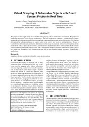
IOP PUBLISHINGJOURNAL OF MICROMECHANICS AND MICROENGINEERINGJ. Micromech. Microeng. 21 (2011) 045009 (12pp) doi:10.1088/0960-1317/21/4/045009<strong>Analysis</strong> <strong>of</strong> <strong>nanoscale</strong> <strong>mechanical</strong><strong>grasping</strong> <strong>under</strong> <strong>ambient</strong> <strong>conditions</strong>Hui Xie 1 , Pierre Lambert 2 and Stéphane Régnier 11 Institut des Systèmes Intelligents et Robotique, Université Pierre et Marie Curie/CNRS UMR7222 BC173, 4 Place Jussieu, 75005 Paris, France2 BEAMS Department, Université libre de Bruxelles, CP 165/56, 50 Avenue FD Roosevelt,B-1050 Bruxelles, BelgiumE-mail: xie@isir.upmc.frReceived 11 October 2010, in final form 16 December 2010Published 4 March 2011Online at stacks.iop.org/JMM/21/045009AbstractIn this paper, in order to <strong>under</strong>stand <strong>mechanical</strong> <strong>grasping</strong> at the <strong>nanoscale</strong>, contact mechanicsbetween nanogrippers and nanoobjects is studied. Contact models are introduced to simulateelastic contacts between various pr<strong>of</strong>iles <strong>of</strong> a flat surface, sphere and cylinder for differenttypes <strong>of</strong> nanoobjects and nanogrippers. Analyses and evaluation instances indicate thatfriction forces, commonly used in macro-<strong>grasping</strong> to overcome gravity, at the <strong>nanoscale</strong> are<strong>of</strong>ten insufficient to overcome the relatively strong adhesion forces when picking up thenanoobject deposited on a substrate due to the tiny contact area. For stable <strong>nanoscale</strong> <strong>grasping</strong>,nonparallel two-finger grippers with a ‘V’ configuration are demonstrated to have better<strong>grasping</strong> capabilities than parallel grippers. To achieve <strong>mechanical</strong> <strong>nanoscale</strong> <strong>grasping</strong>, ananogripper constructed from two microcantilevers is presented. Experimental results for thepick-and-place manipulation <strong>of</strong> silicon nanowires validate the theoretical analyses andcapabilities <strong>of</strong> the proposed nanogripper.(Some figures in this article are in colour only in the electronic version)1. IntroductionGrasping has been widely used to move an object fromone place to another for macro-<strong>mechanical</strong> manipulationand assembly. Research efforts have been made toscale <strong>mechanical</strong> <strong>grasping</strong> down to the microscale withmicrogrippers to integrate functional micro components intomechatronics systems or to perform scientific explorationsin biology [1–6]. Recent work has reported that pickand-placemanipulation at the scale <strong>of</strong> several micrometershas been achieved with a dual-probe gripper [7]. Somebasic micromanipulation problems attributed to the scaleeffects [8], such as suitable <strong>grasping</strong> principles and releasetechniques taking adhesion forces into account, have beenidentified. However, the scale effects become more severe atthe <strong>nanoscale</strong>. In this case, the very tiny size <strong>of</strong> a nanoobjectto be grasped generates higher requirements for <strong>grasping</strong>schemes and nanogripper fabricating techniques.In the past two decades, nanomanipulation has usuallybeen restricted to building 2D nanopatterns or in-planenanomaterial characterization through pushing or pullingmanipulation on a single surface with atomic forcemicroscopes (AFM) [9–12]. Nanostructures have, however,been manipulated, assembled and characterized by nanorobotsequipped with manipulators or grippers in scanning electronmicroscopes (SEM) or transmission electron microscopes(TEM) [13–15], in which <strong>nanoscale</strong> <strong>grasping</strong> can be performeddue to the vacuum environment and the visual feedback.A liquid medium enables noncontact <strong>nanoscale</strong> <strong>grasping</strong>where the adhesion forces are greatly reduced, e.g., opticaltweezer [16]. In order to fabricate smart nanogrippers, carbonnanotube (CNT) materials have been used as self-actuatedgripper fingers [17]. However, the alignment <strong>of</strong> CNT fingersremains a challenge, and the <strong>grasping</strong> capabilities <strong>of</strong> theCNT nanotweezer still need further testing and verification,especially for <strong>grasping</strong> <strong>under</strong> <strong>ambient</strong> <strong>conditions</strong> with thepresence <strong>of</strong> strong adhesion forces.To achieve <strong>mechanical</strong> <strong>nanoscale</strong> <strong>grasping</strong>, the maindifficulties are fabricating very sharp end-effectors with a sizecomparable to the nanoobject to be manipulated and with0960-1317/11/045009+12$33.00 1 © 2011 IOP Publishing Ltd Printed in the UK & the USA
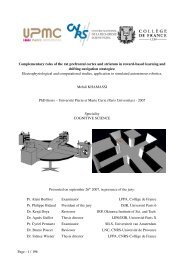
J. Micromech. Microeng. 21 (2011) 045009 HXieet alenough <strong>grasping</strong> force output to overcome strong adhesionforces. Moreover, frictional <strong>grasping</strong> does not work well atthe <strong>nanoscale</strong> because contact-induced friction forces are <strong>of</strong>tenless than the relatively large adhesion forces attributable to thesmall contact areas that are favorable for nanoobject release.In order to <strong>under</strong>stand physical interactions during<strong>mechanical</strong> <strong>nanoscale</strong> <strong>grasping</strong>, based on the Hertz [18], JKR[19], DMT [20] and some other extended theories, variouscontact pr<strong>of</strong>iles among a flat surface, sphere and cylinderfor different types <strong>of</strong> fingers and nanoobjects are analyzed.Grasping capabilities <strong>of</strong> nanogrippers with single and tw<strong>of</strong>ingerconfigurations are discussed and practical designs <strong>of</strong>the nanogripper are proposed. As an example, we presenta prototype <strong>of</strong> AFM nanomanipulation system, in whichtwo collaborative cantilevers with protruding tips are usedto form a dual-tip nanogripper. In our approach, interactionsbetween the nanogripper and the nanoobject during <strong>grasping</strong>are analyzed and simulated theoretically. We have used thedeveloped nanogripper to pick-and-place nanowires.2. Contact mechanics <strong>of</strong> <strong>nanoscale</strong> <strong>grasping</strong>2.1. Problems definitionModeling and simulation <strong>of</strong> contact mechanics between thenanoobject, the gripper and a substrate is necessary toprovide a theoretical estimation <strong>of</strong> <strong>grasping</strong> forces, releaseadhesion forces and maximum contact stress for reliablepickup and smooth release operations, as well as protectingthe gripper and the nanoobject from damage. Research on thefollowing aspects associated with <strong>nanoscale</strong> <strong>grasping</strong> shouldbe addressed.Adhesion force. The effects <strong>of</strong> adhesion during a <strong>nanoscale</strong><strong>grasping</strong> operation are on friction and interfacial wear aswell as a contribution to pickup and release operations, e.g,adhesion forces between a gripper and a nanoobject can beused to counteract substrate adhesion. On the other hand,control and reduction <strong>of</strong> the adhesion between the gripper andthe nanoobject is essential for the release operation.Nanoscale friction. The empirical da Vinci–Amontons’laws, common knowledge in macroscopic friction as relatedto the outcome <strong>of</strong> a collective action <strong>of</strong> a number <strong>of</strong> asperities,are no longer suitable for <strong>nanoscale</strong> contact as it is regarded asa single-asperity contact where the friction is dependent on thecontact area [21] and Young’s modulus [22] <strong>of</strong> the contactinginterface.Contact stress. To protect the brittle gripper and thenanoobject from damage, it is essential to predicate themaximum stress at the contact area and maintain it belowthe contact yield stress. If the adhesion forces, external load,contact area and the stress distribution are known, the contactstress can be accurately estimated.(a)(c)Figure 1. Contact configurations <strong>of</strong> nanowire/tube and nanoparticle(sphere) <strong>grasping</strong> with two-finger grippers. In (a) and(c), thenanowire/tube is grasped by grippers with cylindrical andrectangular fingers, respectively. In (b)and(d), the nanoparticle isgrasped by grippers with cylindrical and rectangular fingers,respectively.Grasping. To pick up the nanoobject, the <strong>grasping</strong> force mustbe greater than the adhesion forces applied on the nanoobjectby the substrate. The <strong>grasping</strong> force may be comprised <strong>of</strong>adhesion forces, friction forces, or other interactive forces.To obtain an adequate and stable <strong>grasping</strong> force, some basicproblems need to be identified, such as interaction analysis,proper gripper configuration design, and choice <strong>of</strong> effective<strong>grasping</strong> strategies and techniques.Release. To release the nanoobject in its target position,interactive forces in the releasing direction applied from thegripper should be less than the adhesion forces from thesubstrate. Solutions are needed to reduce the effects <strong>of</strong> theadhesion forces from the gripper, such as a method to decreasethe contact area, surface modifications, and external actionswith special manipulation schemes.2.2. Contact configurationsFigure 1 shows four configurations <strong>of</strong> <strong>nanoscale</strong> <strong>grasping</strong>configurations using two types <strong>of</strong> two-finger grippers withcylindrical and rectangular fingers. Each configuration usesa nanowire/tube or nanoparticle (sphere). Hence, possiblecontact states between the gripper and the nanoobject beinggrasped can be classified as follows.(i) Contact between two cylinders (C–C), as seen infigure 1(a), where the contact is between a nanowire/tubeand cylindrical fingers.(ii) Contact between a cylinder and a sphere (C–S), as seen infigure 1(b), where a nanoparticle is grasped by cylindricalfingers.(b)(d)2
J. Micromech. Microeng. 21 (2011) 045009 HXieet al(iii) Contact between a flat surface and a cylinder (FS–C).Figures 1(a) and (c) show contacts between a nanowire/tube and the substrate or rectangular fingers.(iv) Contact between a flat surface and a sphere (FS–S), asseen in figures 1(b) and (d) where the contact is betweena nanoparticle and the substrate or rectangular grippers.The contacting states depend on the surface pr<strong>of</strong>ile <strong>of</strong>the gripper’s fingers and the nanoobject with which they arein contact. Contact mechanics <strong>of</strong> these four states will bediscussed in detail in the following parts.2.3. Mechanics analyses <strong>of</strong> different contact pr<strong>of</strong>iles2.3.1. Contact mechanics based on the Hertz theory. In ageneral case, i.e. when two surfaces are brought into contact<strong>under</strong> a load P, assuming that the contact area is elliptical inshape with semi-axes a and b, the size <strong>of</strong> the elliptical contactarea S can be calculated from [23]( ) 23PRe3S = πab = π [F1 (e)] 2 (1)4E ∗and the maximum pressure p 0 on the contact area is given byp 0 =3P ( 6PE∗22πab = [Fπ 3 Re2 1 (e)] −2 , (2)where R e is the equivalent radius <strong>of</strong> the contact area, E ∗are the elastic constants <strong>of</strong> the contact interface, and F 1 (e)is deduced from complete elliptic integrals <strong>of</strong> the argumente = (1 − b2) 1 a 2 2 ,b
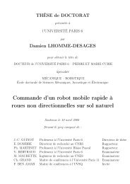
J. Micromech. Microeng. 21 (2011) 045009 HXieet al(a)(b)Figure 2. Nanoscale <strong>grasping</strong> with the single-finger gripper.(a) ‘Tip <strong>grasping</strong>’ method. (b) ‘Side <strong>grasping</strong>’ method.2.4. Friction forces at the contact interfaceThe well-known Amontons’ law shows that a friction forceis proportional to a normal force applied on two contactingsurfaces with many asperities. However, as the contact areareduces to the <strong>nanoscale</strong>, the friction with a single asperitycontact is more suitably described by [29]F f = τS (14)where τ is a effective friction coefficient, and S is the contactarea that is associated with the sum <strong>of</strong> the external forceand the adhesion force. τ is related to the effective shearstress <strong>of</strong> the contact interface: τ ≈ 0.0345 G ∗ [30], whereG ∗ = ( 2−ν 1G 1+ 2−ν )2 −1,G 2ν and G are the Poisson ratio value andshear strength <strong>of</strong> each <strong>of</strong> the contacting surfaces, respectively.3. Nanoscale <strong>grasping</strong> with different grippersGrippers with one or two fingers are widely proposed inmicro/nano-applications. However, grippers with more thantwo fingers may meet difficulties in finger mounting withina limit space, and in simultaneously aligning several fingerswith <strong>nanoscale</strong> accuracy, as well as in releasing nanoobjectfrom excessive adhesive contacts. Thus, single- and two-fingergrippers are discussed.3.1. Grasping with the single-finger gripperFigure 2 shows two <strong>grasping</strong> schemes with a single-fingergripper, namely ‘tip <strong>grasping</strong>’ with fingertip contact and ‘side<strong>grasping</strong>’ using the finger side.3.1.1. ‘Tip <strong>grasping</strong>’. As shown in figure 2(a), in orderto grasp and release a nanoobject with a single finger, thefollowing inequalities should hold:{tFa max > s F a , graspt F a < s (15)F a , releasewhere the adhesion forces t F a and s F a , respectively, comefrom the gripper and the substrate. At present, it is difficultto obtain these inequalities since the contact area <strong>of</strong> the tip–nanoobject contact is <strong>of</strong>ten less than that <strong>of</strong> the nanoobject–substrate contact.Grasping at the atomic scale has been demonstrated usingthe scanning probe microscope (SPM) tip with external energyinduced by electric field trapping [31], tunneling currentinducedheating or inelastic tunneling vibration [32]. Untilrecently, <strong>nanoscale</strong> <strong>grasping</strong> using a single AFM tip hasbeen achieved with electro-enhanced capillary forces [33].However, pick-and-place at the <strong>nanoscale</strong> is still not wellresolved with the ‘tip <strong>grasping</strong>’ method. Difficulties in thiscase are weak <strong>grasping</strong> force outputs while controlling overthe applied forces, as well as release accuracy since thesingle finger has no sufficient geometric limits on the <strong>grasping</strong>operation.3.1.2. ‘Side <strong>grasping</strong>’. Figure 2(b) shows the ‘side <strong>grasping</strong>’method using the following inequalities:{ tFf max > s F a , graspt F f < s (16)F a , releasewhere t F f is the friction force derived from the adhesion forcet F a from the finger side, and s F a is the adhesion force appliedon the nanoobject from the substrate.It is obvious that this method aims to increase t F a throughcontact with the side rather than contact with the tip.t F ashould generally be much larger than s F a to produce enoughfriction force to satisfy the inequalities. In this case, therelease seems more difficult than with the ‘tip <strong>grasping</strong>.’ The‘side <strong>grasping</strong>’ scheme is usually used for nanowire/tube<strong>grasping</strong> in the SEM, which allows many grasp or releaseattempts using visual feedback. However, ‘side <strong>grasping</strong>’ hassimilar difficulties to those for the ‘tip <strong>grasping</strong>’ method, andnanoobject release is to some extent harder.3.2. Nanoscale <strong>grasping</strong> with two-finger grippersFigure 3 shows <strong>nanoscale</strong> <strong>grasping</strong> with two-finger grippers.Grippers with parallel- and nonparallel-finger configurationsare considered.3.2.1. Parallel fingers. Figure 3(a) shows a gripper that hastwo parallel fingers with a tip radius <strong>of</strong> r. To vertically pickup the nanoobject with a radius R, the following inequalitiesshould hold:R>r andt Ff max > 1 s F2 a . (17)During the <strong>grasping</strong> operation, the friction force t F f can beadjusted by increasing or decreasing the repulsive force t F p bydriving single or dual fingers. Similarly, for a stable verticalrelease <strong>of</strong> the nanoobject, the <strong>grasping</strong> force can be reducedto generate a certain value <strong>of</strong> t Ff 0 that makes the nanoobjecteasily stick on the substrate with the following inequalities:t Ff 0 < 1 s F2 a andt Ff 0 t Ff ad (18)where t Ffad is the adhesive friction force derived from t F awithout any external clamping forces.4
J. Micromech. Microeng. 21 (2011) 045009 HXieet al(a)Figure 3. Nanoscale <strong>grasping</strong> with two-finger grippers. (a)Thegripper with parallel fingers. (b) The nonparallel gripper with a ‘V’configuration.MEMS grippers have been used to demonstrate verticallyaligned carbon nanotube pick-up in the SEM [14]. However,this type <strong>of</strong> MEMS grippers might meet difficulties when<strong>grasping</strong> nanotubes attached horizontally to a substrate due totheir coarse fingertips, as well as the small gripper–nanotubecontact area, which cannot provide a sufficient <strong>grasping</strong> force(friction forces). This fact is explored in detail in the example<strong>of</strong> a CNT nanotweezer evaluation given in section 4.3.2.2. Nonparallel fingers. Fingers with a nonparallelalignment with ‘V’ configuration shown in figure 3(b) aredesigned to increase the <strong>grasping</strong> capability. For nonparallelfingers, the following inequalities should hold to successfullypick up the nanoobject:R>r and F g = (t Ff max cos φ + t F p sin φ ) > 1 s F2 a .(19)Obviously, the tilted angle φ makes the <strong>grasping</strong> stronger as aresult <strong>of</strong> the combined effect <strong>of</strong> the clamping forces t F p andthe friction forces t F f to overcome the adhesion forces s F a .3.2.3. Release schemes. The release operation <strong>of</strong> the tw<strong>of</strong>ingergripper is more complicated than the single-fingergripper. Particularly a two-finger gripper with rectangularfingers is used, which produces the comparable adhesionforces t F a and s F a . In contrast, cylindrical fingers mayproduce smaller adhesion forces, resulting in easier nanoobjectrelease.As shown in figure 4(a), in the first step <strong>of</strong> the release, theright finger moves to the right to separate from the nanoobject.In this case, the two opposing adhesion forces from the fingerscancel each other out and the friction force s F f is used to holdthe nanoobject. When the right finger has been separated fromthe nanoobject, the gripper moves upward in figure 4(b)fortherelease operation with the following <strong>conditions</strong>: t F f < s F a .Note that in this last step, the nanoobject may roll with a smallangle due to t M r derived from t F f . However, apart from therelease accuracy, this scheme may be effective for the tw<strong>of</strong>ingergripper release operation.(b)(a)Figure 4. Release operation <strong>of</strong> the two-finger gripper.(a) Horizontally open the gripper by driving the right finger.(b) Vertically release the nanoobject.Table 1. Interfacial contact parameters <strong>of</strong> materials used insimulation and experiments.(b)Silicon SiO 2 GoldSurface energy (Jm −2 ) γ 1.4 0.16 1.5Young’s modulus (GPa) E 160 73 79.5Poisson’s ratio ν 0.17 0.165 0.423.3. Grasping capability comparisons <strong>of</strong> two-finger grippers3.3.1. Grasping force. To compare <strong>grasping</strong> forces <strong>of</strong>the parallel- and nonparallel-finger gripper, an example <strong>of</strong>nanowire <strong>grasping</strong> in air with a cylindrical gripper is simulated.The nanowire is horizontally deposited on a substrate andvertical <strong>grasping</strong> makes an orthogonal contact between thegripper and the nanowire. Suppose that the gripper and thenanowire are made <strong>of</strong> silicon with a very thin SiO 2 coatingand with the same radius <strong>of</strong> 50 nm. t F f can be estimated by(6), (4) and (14) with mechanics parameters <strong>of</strong> Si and γ SiO2 =0.16 J m −2 described in table 1. For t F a calculation, the work<strong>of</strong> adhesion γ at the contact interface is calculated by theDupré equation [34]γ = γ 1 + γ 2 − γ 12 (20)where γ 1 and γ 2 are, respectively, the surface energies <strong>of</strong> thecontact surface, and γ 12 is the interface energy. For two solidcontact surfaces, γ = 2 √ γ 1 γ 2 . The surface energy <strong>of</strong> thewater layer on the contact interface γ H2 O = 0.073 J m −2 .The simulated <strong>grasping</strong> force F g is plotted in figure 5 asa function <strong>of</strong> the angle φ and the clamping force t F p . Theresult shows that the fingers with a smaller tilted angle tend toproduce a greater <strong>grasping</strong> force. For example, as seen in pointA, the parallel gripper, with a clamping force t F p = 2897 nN,generates p 0 = 12 GPa, a yield stress <strong>of</strong> Si at the <strong>nanoscale</strong>(12–13 GPa) [29]. In comparison, the nonparallel gripper witha tilted angle <strong>of</strong> 70 ◦ produces eight times more <strong>grasping</strong> forcethan the parallel gripper with the same clamping force, as seenin point B. In addition, the <strong>grasping</strong> force from the parallelgripper is still below the pickup critical force that is normallyabout several hundreds <strong>of</strong> nanonewton.5
tJ. Micromech. Microeng. 21 (2011) 045009 HXieet al6050FS-S contactC-S contactF f[nN]403020100r = 160 nmr = 120 nmr = 80 nmr = 40 nmr = 20 nmFigure 5. Simulated <strong>grasping</strong> forces F g with different clampingangles.0 40 80 120 160 200R [nm]Figure 6. Simulated adhesive friction forces <strong>of</strong> the rectangular andthe cylindrical grippers.3.3.2. Releasing capabilities. An example <strong>of</strong> <strong>grasping</strong> agold nanoparticle R = 50 nm deposited on a Si substrate witha silicon rectangular gripper is presented. We can calculates F a = t F a = 243 nN using (13) (λ = 3.38) and adhesivefriction forces s F f = t F f = 84 nN using (14) with interfacialcontact parameters <strong>of</strong> Si and gold described in table 1. Thecalculated results show that the gold nanoparticle can besuccessfully released by the rectangular gripper in air. It can beinferred that nanowire release using this scheme is easier thannanoparticle release because <strong>of</strong> the stronger adhesion force <strong>of</strong>the nanowire–substrate contact, as calculated from (8).Theoretical calculation verifies that the rectangulargripper can release the nanoparticle. However, the comparablemagnitudes <strong>of</strong> s F a and t F f introduce uncertainties into therelease process, e.g., the nanoparticle skips from the substrateand sticks to the side <strong>of</strong> the gripper finger even with weakinterferences. From (14), values simulated for the adhesivefriction forces t F f with the rectangular and cylindrical silicongrippers are plotted in figure 6 as a function <strong>of</strong> the goldnanoparticle with different radii R. It shows that t F f will begreatly reduced with a cylindrical finger (r in radius) <strong>under</strong>the same <strong>conditions</strong>. Moreover, t F f can be further reduced byusing thinner cylindrical grippers.3.4. In summary: fabricating a practical nanogripperAs discussed above, the following items are recommended t<strong>of</strong>abricate a practical two-finger nanogripper.(i) Cylindrical fingers (with a circular or elliptical section)with <strong>nanoscale</strong> radii are proposed for generating lowadhesion forces between the grippers and the nanoobjectfor reliable release.(ii) Enough clamping stiffness <strong>of</strong> the gripper is required toproduce sufficient clamping forces.(iii) Nonparallel configuration <strong>of</strong> the finger alignment isrecommended for producing more <strong>grasping</strong> forces thanthe parallel alignment.Figure 7. Nanoscale <strong>grasping</strong> with the CNT nanotweezer.4. Evaluations <strong>of</strong> parallel and nonparallel grippers4.1. Parallel CNT nanotweezerFor further <strong>under</strong>standing the <strong>grasping</strong> capability <strong>of</strong> theparallel-finger gripper, the well-known CNT nanotweezer istaken as an example for <strong>grasping</strong> a gold nanoparticle depositedon a substrate <strong>under</strong> <strong>ambient</strong> environment <strong>conditions</strong>. For theconfiguration shown in figure 7, the dimensions <strong>of</strong> the CNTnanotweezer are r = 22.5 nm and L CNT = 5 μm, and theparameters <strong>of</strong> the contact interface are shown in table 1. Anatural distance between two CNT fingers is d 0 = 100 nm, soa gold nanoparticle radius R = d 0 /2 = 50 nm is adopted.To process the hyperstatic electrode–finger–nanoparticlesystem, as shown in the top inset <strong>of</strong> figure 7, a force <strong>of</strong>constraint o Fp 1 is applied on the upper finger that makes thedisplacement at the end <strong>of</strong> the CNT finger equal to zero.Assuming that the voltage V applied between the two CNTfingers produces a clamping force q per unit length, o Fp 1 iscalculated aso F 1 p = 3 8 qL CNT. (21)6
J. Micromech. Microeng. 21 (2011) 045009 HXieet al6030050 d max=d 0250Clamping force [nN]403020100p 0=8.6 GpStiff caseS<strong>of</strong>t case2001501005006320 30 40 50 60 70Friction force [nN]Figure 8. Frictional <strong>grasping</strong> force <strong>of</strong> the CNT nanotweezer.Due to a complicated deflection expression, d max isassumed to be obtained at 5L CNT /8, which is given byd max =615qL4 CNT(22)32768E CNT Iwhere E CNT is Young’s modulus <strong>of</strong> the CNT, I is the moment<strong>of</strong> inertia <strong>of</strong> the finger given by[ (I = πr4 rin) ] 41 − = πr 4 /4 (r ≫ r in ) (23)4 rwhere r in and r are, respectively, the internal and outer radii<strong>of</strong> the CNT finger.In <strong>ambient</strong> <strong>conditions</strong>, s F a = 58.4 nN and the adhesivefriction t F f = t Ff 1 + t Ff 2 = 20.7 nN are computed,respectively, by (1) and (14) with γ CNT = 0.24 J m −2 , E CNT =1 TPa and ν CNT = 0.165. The result shows that the <strong>grasping</strong>inequality is unsatisfied with only the adhesive friction forces.However, the clamping stiffness <strong>of</strong> the CNT nanotweezerk CNT < 0.01 N m −1 , which is too s<strong>of</strong>t to produce sufficient<strong>grasping</strong> forces to pick up the gold nanoparticle, as seen fromthe blue line in figure 8.Even assuming k CNT →∞to produce enough clampingforces, e.g., t Fp 1 = t Fp 2 = 234 nN for producing a frictional<strong>grasping</strong> force t F f = t Ff 1 + t Ff 2 = 58.4nNtosuits F a , as seenfrom the red line in figure 8, the maximum contact stress p 0 =8.6 GPa exceeds the yield stress <strong>of</strong> gold at the <strong>nanoscale</strong>(around 5–6 GPa at 50 nm due to scale effects [35]) and maydamage the gold nanoparticle. Again, this example proves thatthe main difficulty for <strong>nanoscale</strong> <strong>grasping</strong> is the fabrication <strong>of</strong>sharp end-effectors with enough <strong>grasping</strong> force output.4.2. Nonparallel dual-tip nanogripper4.2.1. Nanogripper configuration. Figure 9 shows thesetup <strong>of</strong> a dual-tip nanogripper that is comprised <strong>of</strong> twoindividually actuated AFM cantilevers with a protruding tip(see the inset, which are tilted at an angle <strong>of</strong> 63 ◦ betweenthe front side <strong>of</strong> tip and the cantilever beam). Nanoscale<strong>grasping</strong> with the proposed nanogripper benefits from itsFigure 9. Nonparallel configuration <strong>of</strong> the dual-tip nanogripper.very tiny tip and a nonparallel ‘V’ configuration, as wellas functions <strong>of</strong> image scanning and force sensing. Detaileddescriptions <strong>of</strong> the system setup and manipulation protocolscan be seen in our previous research [36]. In this work,as supplementary contents, mechanics analyses, quantitativecalculation <strong>of</strong> <strong>grasping</strong> limit improvement and interactiveforce estimation are detailed based on the contact mechanicsresearch addressed above.4.2.2. Grasping mechanics analysis. Figure 10 shows aschematic diagram <strong>of</strong> the analysis <strong>of</strong> the mechanics <strong>of</strong> acantilever used as a gripper finger. In experiments, thecantilever’s beam length L, beam width w and tip length l aremeasured <strong>under</strong> an optical microscope. The beam thickness t isdetermined using the forced oscillation method [37]. Thus, thenormal stiffness kb n and the lateral stiffness kl b<strong>of</strong> the cantilever’sbeam are calculated bykb n = Ewt34L , 3 kl b = Gwt 3(24)3L(l sin φ ′ ) 2where E and G are, respectively, the Young and shear modulus<strong>of</strong> the cantilever, and φ ′ = 60 ◦ is the tilted angle through therotation axis <strong>of</strong> the tip relative to the substrate.When a force F is applied at the end <strong>of</strong> the cantilever’stip, it moves with the displacements δ x , δ y and δ z that dependon the stiffness <strong>of</strong> the cantilever on each axis in the definedframe. As seen in insets (I) and (II) <strong>of</strong> figure 10, the decoupleddisplacement on each axis is calculated by[ ] [ ] ⎡ d F xδx sin α sin φ′l sin φ ′ b+ d F ⎤zb⎢=δ ⎣z cos α cos φ ′ l cos φ ′ d F xt + d F z⎥t ⎦ , (25)θ F xb+ θ F zb( 1δ y = F ykbl + 1 )(26)k twhere α is the mounting angle <strong>of</strong> the cantilever, θ is the angulardeflection <strong>of</strong> the beam d is the deflection <strong>of</strong> the cantilever’sbeam and tip (respectively labeled by subscripts b and t, andwith superscripts <strong>of</strong> forces F x and F z ), and k t is the stiffness<strong>of</strong> the cantilever’s tip. The calculation <strong>of</strong> the deflections isdetailed in appendix B. The tip close to its very end is7
J. Micromech. Microeng. 21 (2011) 045009 HXieet alFigure 11. Force diagram using the nonparallel dual-tipnanogripper.Figure 10. <strong>Analysis</strong> <strong>of</strong> the mechanics <strong>of</strong> the gripper finger (AFMcantilever) during a <strong>grasping</strong> operation.assumed to be symmetrical in shape; thus, it has the samestiffness on each axis: k t ≈ 20 N m −1 simulated by the finiteelement method. From (24), the overall lateral stiffness <strong>of</strong> thecantilever is about 19 N m −1 , which makes the tip alignmentmore stable during the <strong>grasping</strong> operation.4.2.3. Grasping capabilities. Figure 11 shows a forcesimulation for a nanoobject (with a circular section,e.g., nanowires) <strong>grasping</strong> operation using the proposednanogripper. Equations can be obtained for a staticequilibrium:{Fx = ( t F p sin φ − t F f cos φ)F z = ( t F p cos φ + t F f sin φ) = 1 s (27)F2 awhere φ = 68 ◦ with a mounting angle 5 ◦ <strong>of</strong> the cantilever.t F f can be calculated by (4) and (14):[ 3( t t F p + t ] 2F a )R3 eF f = τπ [F1 (e)] 2 (28)4E ∗where t F a = o F a , the adhesion force calculated by (3); t F p ,the repulsive force from tips, is significant for estimating themaximum stress on the contacting area using (5) to avoiddamage to both the nanogripper and the nanoobject.The normal force F z and the lateral force F l applied onthe end <strong>of</strong> the tip can be calculated from the voltage outputsV n and V l <strong>of</strong> optical levers byk n b δ n = k n b(dF xb+ d F zb)= Vn S n , (29)F y = V l S l (30)where δ n is the normal displacement on the end <strong>of</strong> the cantileverbeam, S n and S l are, respectively, the normal and lateralsensitivities <strong>of</strong> the optical lever. When V n is detected andt F a is determined, F x and F z can then be calculated by (27).Figure 12. Simulation <strong>of</strong> the <strong>grasping</strong> limit on the size <strong>of</strong> thenanoobject.As shown in figure 12, for a successful <strong>grasping</strong>, the angleη as well as the dig-in distance ξ should be positive. Theirrelation is given by⎡ √⎤(R − r)2ξ = R(1 − cos η) = R ⎣1 − 1 − ⎦(R + r) 2 . (31)During the pickup, the beam and tip deflections cause asmaller ξ ′ , and the grasp is probably lost as ξ is reduced tozero. Thus, the minimum radius <strong>of</strong> the nanoobject R min canbe estimated by assuming that δx max ξ with known s F a ,parameters <strong>of</strong> the nanogripper and the contacting interface,e.g., Young’s modulus, shear modulus and surface energy.R min can be estimated from the following procedure.(i) Calculate the adhesion forces s F a and t F a withapreestimatedsize limit R 0 <strong>of</strong> the nanoobject; then calculatethe corresponding t F a and t F f using (27) and (28).(ii) When F x and F z are calculated by (27), R min can thenbe estimated using (25) and (31). Then calculate a newestimation R 1 = (R 0 + R min )/2 and repeat the steps withR 1 until the difference between the estimation R 1 and thecalculated R min in successive iterations is less than thepredefined R = 0.5 nm.8
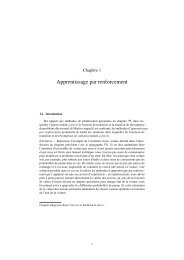
J. Micromech. Microeng. 21 (2011) 045009 HXieet alR min[nm]36343230282624222034.3 nm28.9 nm21.5 nmincrease k n bincrease k t0 50 100 150 200 250 300Stiffness [N/m](a)k n (k = 20 N/m)b tk tk n b = 4 N/m)R min[nm]36322824201612834.3 nm17.6 nm8 nmincrease t F p0 20 40 60 80 100 120Preload t F p[nN](b)Side contactTip contactFigure 13. Improving <strong>grasping</strong> limit by (a) increasing stiffness <strong>of</strong> the cantilever beam k n b or tip k t and (b) t F p preloading.Figure 14. Pre-scanned image <strong>of</strong> the SiNW. The insets show a 3D topographic image <strong>of</strong> the tip II and the nanowire height at thelocation A–A.Table 2. Dual-tip nanogripper parameters.k n b k t L l r α s F a4Nm −1 20 N m −1 250 μm 10 μm 8nm 5 ◦ 100 nNGrasping limit can be improved by increasing kb n and k t.As seen in figure 13(a), with parameters described in table 2( s F a is given), the simulated results indicate that a stiffertip is more effective than a stiffer beam for reducing R min .The former provides a lower limit <strong>of</strong> 21.5 nm and the later28.9 nm.In addition, if a preload <strong>of</strong> t F p is applied before <strong>grasping</strong>,the nanogripper will hold the SiNW more tightly with astronger t F f , thereby significantly reducing R min . As shownin figure 13(b), the <strong>grasping</strong> limit can theoretically equal theradius <strong>of</strong> the tip apex with a proper preload. However, whenthe radius <strong>of</strong> the nanoobject decreases to 17.6 nm, it becomesdifficult to grasp because <strong>of</strong> the contact with the tip apex(sphere–sphere contact). Thus, with this means, R min reachesthe limit <strong>of</strong> 17.6 nm, while t F p = 83 nN. However, thepreloading involves great risks in damaging the tips as wellas the nanoobjects. In this case, the maximum stress p 0 on thecontact area should be guaranteed less than the yield stress <strong>of</strong>the contact.4.2.4. Silicon nanowires <strong>grasping</strong> and assembly. Inexperiments, silicon nanowires (SiNWs) were deposited ona freshly cleaned silicon wafer. A pre-scanned image is shownin figure 14, which includes the topographic image <strong>of</strong> SiNWs,and the local image <strong>of</strong> tip II (see the zoomed inset). A <strong>grasping</strong>location on the left SiNW is marked A–A, where the SiNWhas a height <strong>of</strong> 153 nm. The left SiNW will be transportedto the target position where it will be released onto the rightSiNW to build a nanocrossbar.Figure 15 shows an example <strong>of</strong> contact detection with tipII: seen as icons in the graph, the cantilever is bent upwardresulting in positive forces about 5 nN when it snaps in thenanowire. As the tip makes contact with the SiNW, it starts todig into the root <strong>of</strong> the SiNW and further movement does notlead to obvious change. During the retraction, the adhesionforces between the tip and the substrate induce a suddendecrease in the bending force to about 48 nN. After the contactbreaks with the substrate, the bending force reaches a positivepeak before the tip pulls <strong>of</strong>f the nanowire. When the tip digsinto the SiNW, the cantilever produces a pre-<strong>grasping</strong> forceF 1 = 27 nN calculated from a voltage difference <strong>of</strong> about20 mV and the normal force conversion factor <strong>of</strong> 1.36 on tipII. The corresponding pre-load on the tip II is estimated ast F p = 26 nN using (27).9
J. Micromech. Microeng. 21 (2011) 045009 HXieet alFigure 15. Contact detection by normal force sensing on tip II.Figure 16 shows the curve <strong>of</strong> the peeling forcespectroscopy on one <strong>of</strong> the tips during the pick-and-placemanipulation <strong>of</strong> the same SiNW. The curve starts fromthe contact state between the nanogripper, the SiNW andthe substrate. As the nanogripper is moved to pick up theSiNW, the cantilever is bent downward creating negativeforces until the cantilever pulls <strong>of</strong>f the substrate with a voltagedifference <strong>of</strong> 75 mV indicating a pull-<strong>of</strong>f force F 2 = 103 nN.As the nanogripper is moved up further, the force magnitudegradually keeps increasing with the SiNW peeling forceresponses. Retraction leads to a continuous decrease exceptfor a weak fluctuation at 178 nm. Snap-in occurs at 25 nmafter a mild force decrease. With even further retraction, themagnitude <strong>of</strong> the normal force approaches the prior state before<strong>grasping</strong>.The maximum peeling force occurs at retraction start,where the voltage is about −105 mV indicating a <strong>grasping</strong>force <strong>of</strong> F 3 = 144 nN. At this point, from calculation,t F f = 31 nN that is much smaller than the SiNW–substrateadhesion force, and t F p = 218 nN that generates a maximumcontact stress p 0 = 7.1 GPa, with R ≈ 19.5 nm at the contactFigure 16. Force detection on one <strong>of</strong> the tips during the <strong>grasping</strong>and release operation.location <strong>of</strong> 55 nm from the tip end. Fortunately, this contactstress is still below the yield stress <strong>of</strong> silicon [29].The post-manipulation image in figure 17 verifies that theSiNW has been successfully transported and piled on anotherSiNW, building a nanocrossbar with a maximum height <strong>of</strong>about 500 nm. During the pick-and-place manipulation, oncethe SiNW was reliably grasped, the nanogripper moved up800 nm at a velocity <strong>of</strong> 80 nm s −1 ; then the SiNW wastransported a distance <strong>of</strong> 4.05 μm ontheX-axis at a velocity<strong>of</strong> 150 nm s −1 and 1.95 μm ontheY-axis at a velocity <strong>of</strong>72 nm s −1 .The SiNWs can be successfully grasped by the proposednanogripper. However, failure sometimes occurred when<strong>grasping</strong> positions were located at the middle part <strong>of</strong> theSiNWs, which jumped from the substrate and then adhered tothe nanogripper during the pickup or transportation process.To avoid such failures, <strong>grasping</strong> locations are stronglyrecommended at the end <strong>of</strong> the nanowires/tubes. In addition,the nanowires/tubes should keep in contact with the substratethroughout the pick-and-place process.(a)(b)Figure 17. Pick-and-place manipulation results for the SiNWs. (a) A post-manipulation image verifies that the manipulated SiNW is piledon another SiNW. (b) 3D topographic image <strong>of</strong> the manipulation result.10
J. Micromech. Microeng. 21 (2011) 045009 HXieet al5. ConclusionTo <strong>under</strong>stand the interactive phenomena between ananogripper and a nanoobject, contact mechanics weremodeled for different contact pr<strong>of</strong>iles. Contact modeling madeit easy to estimate the interfacial adhesion forces, deducecontact friction forces and contact stress, thereby providinga theoretical analysis for the gripper design. To furtherimprove our <strong>under</strong>standing, <strong>grasping</strong> strategies with tw<strong>of</strong>ingergrippers were discussed. The analysis shows that thegripper with a nonparallel configuration has better <strong>grasping</strong>capabilities than the parallel configuration. A homemadenanogripper constructed from two AFM cantilevers with a ‘V’configuration was introduced. The <strong>grasping</strong> capabilities <strong>of</strong> theproposed nanogripper were analyzed in detail and ways forimproving the <strong>grasping</strong> limitation were presented. Contactmechanics between the tip and the silicon nanowire (thecylinder–cylinder contact configuration) has been analyzedwith the modified Hertz model, with which forces appliedon the contact area have been estimated, and results showthat silicon nanowires can be nondestructively graspedby the proposed dual-tip nanogripper. Subsequently, thenanogripper’s capabilities were validated by a successfulpick-and-place manipulation <strong>of</strong> silicon nanowires to build ananocrossbar. As a result, the theoretical analyses and theexperimental results validate the <strong>nanoscale</strong> <strong>grasping</strong> schemesand methods with two-finger grippers.AcknowledgmentsThis work was supported in part by the ANR (French ResearchAgency) through the NANOROL Project <strong>under</strong> ANR grantno PSIROB07-184846. The authors would like to thankPr<strong>of</strong>essor Sinan Haliyo and Sébastien Alvo for their valuablediscussions.Appendix A. List <strong>of</strong> selected symbolst F fs F ft F as F ao F aαφφ ′ψηξkbnk tS nS lfriction force on a nanoobject from a tipfriction force on a nanoobject from a substrateadhesion force on a nanoobject from a tipadhesion force on a nanoobject from a substrateadhesion force on a gripper from a nanoobjectcantilever mounting angletilted angle <strong>of</strong> a tip through its front edgetilted angle <strong>of</strong> a tip through its rotation axisinclined angle between axes <strong>of</strong> contact surfaceseffective <strong>grasping</strong> angle relative to the substrateeffective <strong>grasping</strong> distancenormal stiffness <strong>of</strong> a cantilever’s beamstiffness <strong>of</strong> the cantilever’s tipnormal sensitivity <strong>of</strong> a optical leverlateral sensitivity <strong>of</strong> a optical leverAppendix B. Deflections on the cantileverDeflections on the cantilever’s beam and tip can be calculatedbyd F xb= F )x 3l sin φ′(sinkbn α + (B.1)2Ld F zbθ F xbθ F zb= F z(coskbn α +d F xt = F x sin φ ′k td F zt = F z cos φ ′k t= 3F (x sin αkb nL +2= 3F (z cos αkb nL +2)3l cos φ′2L)l sin φ′L(B.2)(B.3)(B.4)(B.5))l cos φ′. (B.6)LSymbolrRSp 0LwtlEGE ∗τPF sγt F po F pDescriptionradius <strong>of</strong> a tip apexradius <strong>of</strong> a nanoobject being manipulatedcontact areamaximum pressure on a contact areacantilever beam lengthcantilever beam widthcantilever beam thicknesscantilever tip lengthYoung’s modulusshear moduluscombined elastic moduluseffective friction coefficientexternal loadadhesion forcework <strong>of</strong> adhesionclamping force <strong>of</strong> a tiprepulsive force on a gripper from a nanoobject11References[1] Driesen W, Varidel T, Régnier S and Breguet J M 2005Micromanipulation by adhesion with two collaboratingmobile micro robots J. Micromech. Microeng. 15 S259–67[2] Xie H, Rong W B and Sun L N 2007 A flexible experimentalsystem for complex microassembly <strong>under</strong> microscale forceand vision-based control Int. J. Optomechatronics 1 80–102[3] Walle B L, Gauthier M and Chaillet N 2008 Principle <strong>of</strong> asubmerged freeze gripper for microassembly IEEE Trans.Robot. 24 897–902[4] Kim K Y, Liu X Y, Zhang Y and Sun Y 2008 Nanonewtonforce-controlled manipulation <strong>of</strong> biological cells using amonolithic MEMS microgripper with two-axis forcefeedback J. Micromech. Microeng. 18 055013[5] Neild A P, Oberti S, Beyeler F, Dual J and Nelson B J 2006 Amicro-particle positioning technique combining anultrasonic manipulator and microgripper J. Micromech.Microeng. 16 1562–70[6] Zhang Y, Chen B K, Liu X Y and Sun Y 2010 Autonomousrobotic pick-and-place <strong>of</strong> micro objects IEEE Trans. Robot.26 200–7
J. Micromech. Microeng. 21 (2011) 045009 HXieet al[7] Xie H and Régnier S 2009 Three-dimensional automatedmicromanipulation using a nanotip gripper withmulti-feedback J. Micromech. Microeng. 19 075009[8] Menciassi A, Eisinberg A, Izzo I and Dario P 2004 From‘macro’ to ‘micro’ manipulation: models and experimentsIEEE/ASME Trans. Mechatronics 9 311–20[9] Resch R, Lewis D, Meltzer S, Montoya N, Koel B E,Madhukar A, Requicha A A G and Will P 2000Manipulation <strong>of</strong> gold nanoparticles in liquid environmentsusing scanning force microscopy Ultramicroscopy82 135–9[10] Sitti M 2004 Atomic force microscope probe based controlledpushing for nanotribological characterization IEEE/ASMETrans. Mechatronics 9 343–9[11] Liu L, Luo Y, Xi N, Wang Y, Zhang J and Li G 2008 Sensorreferenced real-time videolization <strong>of</strong> atomic forcemicroscopy for nanomanipulations IEEE/ASME TMechatronics 13 76–85[12] Xie H, Haliyo D S and Reǵnier S 2009 Parallelimaging/manipulation force microscopy Appl. Phys. Lett.94 153106[13] Fukuda T, Arai F and Dong L X 2003 Assembly <strong>of</strong>nanodevices with carbon nanotubes through nanoroboticmanipulations Proc. IEEE 91 1803–18[14] Carlson K, Andersen K N, Eichhorn V, Petersen D H,Mølhave K, Bu I Y Y, Teo K B K, Milne W I, Fatikow Sand Bøggild P 2007 A carbon nan<strong>of</strong>ibre scanning probeassembled using an electrothermal microgripperNanotechnology 18 345501[15] Sardan O, Eichhorn V, Petersen D H, Fatikow S, Sigmund Oand Bøggild P 2008 Rapid prototyping <strong>of</strong> nanotube-baseddevices using topology optimized microgrippersNanotechnology 19 49550[16] Bosanac L, Aabo T, Bendix P M and Oddershede L B 2008Efficient optical trapping and visualization <strong>of</strong> silvernanoparticles Nano Lett. 8 1486–91[17] Kim P and Lieber C M 1999 Nanotube nanotweezers Science286 2148–50[18] Hertz H 1881 On the contact <strong>of</strong> elastic solids J. Reine Angew.Math. 92 156–71[19] Johnson K L, Kendall K and Robert A D 1971 Surface energyand the contact <strong>of</strong> elastic solids Proc. R. Soc. Lond.A 324 301[20] Derjaguin B V, Muller V M and Toporov Y P 1975 Effect <strong>of</strong>contact deformations on the adhesion <strong>of</strong> particles J. ColloidInterface Sci. 53 314[21] Ritter C, Heyde M, Stegemann B and Rademann K 2005Contact-area dependence <strong>of</strong> frictional forces: movingadsorbed antimony nanoparticles Phys. Rev. B71 085405[22] Riedo E and Brune H 2003 Young modulus dependence <strong>of</strong>nanoscopic friction coefficient in hard coatings Appl. Phys.Lett. 83 1986–8[23] Johnson K L 1985 Contact Mechanics (Cambridge:Cambridge University Press)[24] Schwarz U D 2003 A generalized analytical model for theelastic deformation <strong>of</strong> an adhesive contact between a sphereand a flat surface J. Colloid Interface Sci. 261 99–106[25] Wu X F and Dzenis Y A 2007 Adhesive contact in filamentsJ. Phys. D: Appl. Phys. 40 4276–80[26] Chaudhurya M K, Weaver T, Hui C Y and Kramer E J 1996Adhesive contact <strong>of</strong> cylindrical lens and a flat sheet J. Appl.Phys. 80 30–7[27] Johnson K L and Greenwood J A 2008 A Maugis analysis <strong>of</strong>adhesive line contact J. Phys. D: Appl. Phys. 41 155315[28] Maugis D 1992 Adhesion <strong>of</strong> spheres: the JKR–DMT transitionusing a Dugdale model J. Colloid Interface Sci. 150 243–69[29] Bhushan B 2004 Springer Handbook <strong>of</strong> Nanotechnology(Heidelberg: Springer)[30] Dedkov G 1999 Friction on the <strong>nanoscale</strong>: new physicalmechanisms Mater. Lett. 38 360–6[31] Whitman L J, Stroscio J A, Dragoset R A and Cellota R J 1991Manipulation <strong>of</strong> adsorbed atoms and creation <strong>of</strong> newstructures on room-temperature surfaces with a scanningtunneling microscope Science 251 1206–10[32] Avouris P 1995 Manipulation <strong>of</strong> matter at the atomic andmolecular-levels Acc. Chem. Res. 28 95–102[33] Toset J and Gomila G 2009 Three-dimensional manipulation<strong>of</strong> gold nanoparticles with electro-enhanced capillary forcesAppl. Phys. Lett. 96 043117[34] Israelachvili J N 1992 Intermolecular and Surface Forces(New York: Academic)[35] Wu B, Heidelberg A and Boland J J 2005 Mechanicalproperties <strong>of</strong> ultrahigh-strength gold nanowires NatureMater. 4 525[36] Xie H, Haliyo D S and Régnier S 2009 A versatile atomicforce microscope for three-dimensional nanomanipulationand nanoassembly Nanotechnology 20 215301[37] Xie H, Vitard J, Haliyo D S and Régnier S 2008 Enhancedaccuracy <strong>of</strong> force application for AFM nanomanipulationusing nonlinear calibration <strong>of</strong> optical levers IEEE Sens. J.8 1478–8512