Create successful ePaper yourself
Turn your PDF publications into a flip-book with our unique Google optimized e-Paper software.
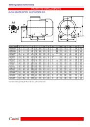
Rotating electrical machines manufactured according to PN –EN-60034-7.Horizontal shaftVertical shaftMarkingMarkingSystem II System I System II System IIM 1001 IM B3 IM 1011 IM V5IM 1051 IM B6 IM 1031 IM V6IM 1061 IM B7 IM 2011 IM V15IM 1071 IM B8 IM 2031 IM V36IM 2001 IM B35 IM 3011 IM V1IM 2101 IM B34 IM 3031 IM V3IM 3001 IM B5 IM 3611 IM V18IM 3601 IM B14 IM 3631 IM V19OPERATING MANUAL – THREE- PHASE SQUIRREL- CAGE INDUCTION MOTORS 4/32PUBLICATION DATE: 9.05.2011 - EDITION 4
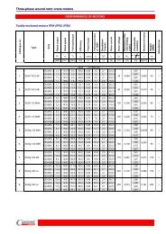
Force acting on the shaft extension should not exceedthe permissible values included in the following chart.Motor type Horizontal operation* Vertical operationNumber of polesFa2FpFa2FpFa1Fa1F p F a1 = F a2 F p F a1 F a2Sg 80 2 0.44 0.13 0.44 0.10 0.134 0.51 0.17 0.51 0.12 0.172 0.68 0.44 0.68 0.35 0.38Sh 90 4 0.78 0.44 0.78 0.35 0.386 0.96 0.44 0.96 0.35 0.388 1.05 0.44 1.10 0.35 0.382 0.88 0.46 0.90 0.28 0.40Sg 100 4 1.06 0.46 0.98 0.38 0.406 1.20 0.46 1.10 0.38 0.408 1.43 0.46 1.30 0.38 0.402 1.00 0.48 1.00 0.40 0.45Sg 112 4 1.45 0.48 1.40 0.40 0.456 1.62 0.48 1.60 0.40 0.458 1.85 0.48 1.90 0.40 0.452 1.82 0.66 1.90 0.43 0.60Sg 132 4 2.10 0.66 2.20 0.45 0.606 2.80 0.66 2.80 0.50 0.608 2.90 0.66 2.95 0.50 0.602 2.22 0.98 2.30 0.92 0.95Sg 160 4 2.40 0.98 2.40 0.92 0.956 2.85 1.10 2.90 0.98 1.008 3.20 1.10 3.20 0.98 1.002 2.92 1.30 3.00 1.10 1.20Sg 180 4 3.60 1.30 3.60 1.10 1.306 4.00 1.80 4.10 1.40 1.708 4.45 1.80 4.50 1.50 1.80* - forces listed in the chart and applied to the middle of the shaft neck's length.OPERATING MANUAL – THREE- PHASE SQUIRREL- CAGE INDUCTION MOTORS 5/32PUBLICATION DATE: 9.05.2011 - EDITION 4
OPERATING MANUAL – THREE- PHASE SQUIRREL- CAGE INDUCTION MOTORS 6/32PUBLICATION DATE: 9.05.2011 - EDITION 4
2. TRANSPORTATION AND STORAGEATTENTION!When lifting drive units always use lifting handles designed for this purpose.Motors should be transported packaged, in roofed vehicles, avoiding sudden shocks and impact, secured againstmechanical damage and humidity. Packaging should adequately protect the motor from mechanical damage duringtransport.When lifting the motor or moving it without the packaging, use the lifting eye bolt located at the top of the frame inthe middle part of the motor. Do not attach the rope to motor elements which stick out, such as the terminal box,mounting feet, shaft neck, etc.Motor should be stored in a storage space, where: dust, fumes and acrid vapours and other aggressive chemical fumes which can damage the isolation or thecover cannot enter; maximum relative humidity does not exceed 80 at 20°C; in case of motors with heating or anti condensation elements, they can be plugged into mains, temperature of the surroundings is between -10°C a nd +40°C, no vibrations occur.It is important to protect processed surfaces of motors in storage from atmospheric impact, by covering them withthick grease or easily removable anti-corrosion paint.ATTENTION!After storing a motor for a period of three years, its bearings should be replacedfor new ones, or the greasing should be replaced.3. MOTOR INSTALLATION.ATTENTION!Prior to starting any work on the motor, make sure that it is unplugged frommains.3.1 Inspecting the motor prior to the assembly.Before starting the motor, check: whether the motor complies with your order, whether the motor's rated voltage confirms with the network voltage, whether the motor hasn't been damaged during transportation or storage; whether the motor's rotor rotates freely (turn it <strong>manual</strong>ly), whether the surrounding temperature in the location of the motor's installation does not exceed + 40°C, (formaritime motors,+45°C or +50°C, according to the ma ritime association regulations), whether free flow of cooling air, necessary for proper operation of the motor, will be provided,Minimal distance between the end the motor's frame and other elements: for shaft height 90 mm – 15 mm for shaft height 100 and 112 mm – 20 mm for shaft height 132, 160 and 180 mm – 40 mmtightness of all mounting screws on the motor.3.2 Checking of the insulation resistance.Inspection of the insulation's condition should be done prior to starting the motor, if moistness of the winding issuspected, or after a lengthy standstill or storage period (about 6 months).Insulation resistance should be measured using 500V direct current.ATTENTION!During, and directly after measuring the insulation resistance, harmful voltage ispresent in the terminals, therefore it is forbidden to touch them. In order to removethe threat of electrocution, it is necessary to discharge the winding.The minimal value of the insulation resistance in regard to the frame or between phases in the temperatureof 25°C ± 15°C for a new or repaired motor is 10 M Ω.OPERATING MANUAL – THREE- PHASE SQUIRREL- CAGE INDUCTION MOTORS 7/32PUBLICATION DATE: 9.05.2011 - EDITION 4
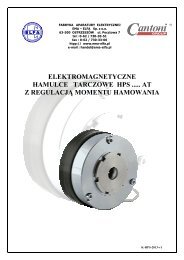
While the motor is in operation, the insulation resistance may drop, however, it cannot be below the criticalinsulation resistance value, which is a product of inter-wire supply voltage and constant coefficient0.5MΩ/kV. In case of a motor powered by a frequency converter, the minimal value of the motor's insulationresistance is 1 MΩ. During the measurement, the winding should be in <strong>operating</strong> temperature.An example of a motor powered from a 3 x 400V network: 0,4kV x 0,5MΩ/kV= 0,2 MΩ.If the expected winding resistance falls below the level of the critical resistance value, the motor should beimmediately taken out of service and the cause of the lowered resistance value - moistness, pollution, damage, etc -removed. After the repair or drying, the conditions of insulation should be checked again. .During the drying process, create conditions necessary to remove moisture from the winding, i.e. at least, take offthe cover of the terminal box in order to make the exchange of air with the interior of the motor possible. For motorsizes 132, 160 and 180, there is a possibility to drain the condensate by unscrewing the drain plugs installed in thebearing brackets. The recommended drying temperature is 60 to 80°C. The motor should be dried until in sulationresistance reaches its minimal value (2-8h).In case of motors with heating elements, drying can be performed by connecting them to the mains. Anothermethod of drying is single-phase powering of two out of the three motor outlets with a voltage with a value of about0.2 of the rated voltage. This way, the motor will not spin, and the value of the input current will be from 25% to 35%of rated current. Heating the motor's winding using the heating elements or single-phase powering prevents thecondensation of steam and can be done during the whole period of standstill.3.3 Placing the geared pulley or half coupling on the motor's shaft extension.Prior to placing the geared pulley or the half coupling on the motor's shaft extension: remove any possible injury marks from the shaft extension, remove protective paint from the shaft extension, lightly cover the shaft extension with grease, clean anti-corrosion layer from the flange disc,Placing the geared /wedged/ pulley or the half coupling should be done with the use of an appropriate tool, asshown in fig. 1 – using the threaded centre hole of the shaft extension.Fig. 1If necessary, heat up the coupling hub or the pulley /belt, geared/ to about 80°C.In no special equipment is available, the heated up coupling or geared pulley can be hammered on using a suitablesleeve, simultaneously supporting the opposite shaft extension, so the force from the hits is transferred to thesupport, not the bearings.After putting the belt, wedged, geared pulley or half coupling on the shaft extension, secure it from sliding off theshaft using a screw with a washer, screwed in the threaded centre hole of the shaft extension.OPERATING MANUAL – THREE- PHASE SQUIRREL- CAGE INDUCTION MOTORS 8/32PUBLICATION DATE: 9.05.2011 - EDITION 4
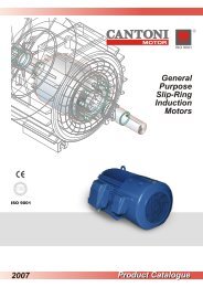
3.4 Motor orientationMotor should be oriented in such a way so that it is structurally adapted as much as possible to have easy accessfor inspection and operations relating with its maintenance.Motor on mounting legs can be mounted directly on anchor bolts or on take-ups allowing for belt tensionadjustment.When connecting the motor to the driven appliance using a coupling, particular attention needs to be given to theconcentricity of shafts: the motor and of the driven machine's shafts – as shown in fig. 2.For belt drives, it is recommended to use transmissions with wedge belts, which have: smaller slide, quieter operation, lower belt tension.Lower belt tension results in a lower risk of damaging motor's bearing from the drive side.Correct assembly and appropriately balanced coupling element have a significant effect on the drive'svibrations and quite operation.CorrectsettingMaximum permissible non-concentricitya = 0.25 mmb = b 2 - b 1 = 0.1mm/∅ 200mmFig.2 Motor orientation3.5 Connecting the motor to the mains.ATTENTION!The earthing or the protective conductor should be connected to the terminal markedwith the earthing symbol located in the terminal box or on the motor's frame.Earthing conductor profiles are specified in attachment no. 3.Each motor has a rating plate attached to its frame. This rating plate includes information such as: supply voltage – permissible deviation ±5% not requiring decreasing the power; supply voltage frequency – permissible deviation ±2% not requiring decreasing the power; connection of the 3-phase winding in a star (Y) or a delta (∆); input current at rated load.The box contains a terminal board with 3 or 6 terminals. Power cables should be led in to the terminal box throughstuffing boxes or glands. The screwed in cable inlets should prevent water and dust from entering the terminal boxduring operation. Stuffing box throttle range is included in attachment no. 1.Power leads should have a cable tips. Torque values, with which the nuts and screws of the electric connectionsshould be tightened, are listed in attachment no. 2.Detailed rules regarding installing electric motors are given in PN-E-05012.OPERATING MANUAL – THREE- PHASE SQUIRREL- CAGE INDUCTION MOTORS 9/32PUBLICATION DATE: 9.05.2011 - EDITION 4
3.5.1 Direct (DOL) starting.Each motor is adapted for direct starting.In case of a 3-terminal board, motor is designed for one voltage, which is indicated on the rating plate. Direct startcan take place by plugging directly into the mains, after making sure that the inter-wire voltage of the mains is equalto the rated voltage of the connected motor.In case of a 6-terminal board, using the connectors supplied with the motor, create a correct phase match, meaningY or ∆, and connect the power supply to the terminals in accordance to the connection diagram attached with themotor – attachment no. 4.An example: motor marked 230/400Y V can be connected in two ways, depending on the supply network: in a ∆ connection if inter-wire voltage is 3 x 230V or in a Y connection if inter-wire voltage is 3 x 400V.3.5.2 Indirect (0-Y-∆) starting.0-Y-∆ start can take place only in motors with 6–cioma outlets from one winding, and supply voltage must be equalto the motor's rated voltage in a ∆ connection. Connectors should be removed from the terminal board.Indirect starting is used in order to limit the motor's starting current and large drops of voltage in the mains as aneffect of high starting voltage. Remember that the motor with a nominal connection in ∆ has a 3 times smallerstarting torque in an Y connection, that's why the 0-Y-∆ start should be performed without load or with the lowestpossible load. Start of the motor begins with the Y connection, and after achieving a stable rotational speed by themotor, switches to ∆. If the motor cannot start in the Y connection, instead of using the 0-Y-∆ start, use the directstart method. If start is still impossible, reanalyze the starting conditions and motor selection.An example: starting a motor marked 400∆/690YV or 400∆V powered by a 3 x 400V network: connection in Y – operation 10s, switch to ∆ - constant operation, put the motor under load.Detailed regulations regarding installing electric motors are given in PN-E-05012.3.5.3 Direction of the motor's rotation.The standard direction of rotation is clockwise, as seen from the shaft extension's drive side, when the power supplyphases L1, L2, L3 are connected according to the diagram attached with the motor – attachment no. 4. In order tochange the rotation direction, change any two power supply phases.3.5.4 Winding thermal protection – included upon request.Two types of thermal protection are used in motors: thermal bimetal, PTC-resistor.Terminals of PTC-resistor temperature sensors should be connected with the appropriate input terminals on theresistance relay, and terminals of thermal bimetal NC temperature sensors can be connected directly to the motor'ssafety circuit (fig 4).Motors, in which the stator's winding has buried thermal protection, have finishing leads of the beginnings and endsof temperature sensors, which are connected in series, connected to an additional terminal block, in the terminalboxes.Thermocontact sensors.Three thermocontacts are located in the motor's winding, connected in series (fig. 3). Each one is placed in adifferent phase.Fig. 3T 1 T 1OPERATING MANUAL – THREE- PHASE SQUIRREL- CAGE INDUCTION MOTORS 10/32PUBLICATION DATE: 9.05.2011 - EDITION 4
An example of the power supply system of a motor with thermal protection using thermocontacts is presented indrawing 4a.Fig. 4Technical parameters of thermocontact S01.150.05: contact opening temperature - 150ºC°C ±5ºC°C rated current - 250V, 50 ÷ 60Hz load: 2,5A at cosφ=1 1,6A at cosφ=0,6 max load – 40.A at cosφ=1 contact system – normally closed electric resistance of the insulation – 2.0kV resistance - 4000 Ω rated current - ≤2,5V- max current – 30V- electric resistance of the insulation – 2.5kVOPERATING MANUAL – THREE- PHASE SQUIRREL- CAGE INDUCTION MOTORS 11/32PUBLICATION DATE: 9.05.2011 - EDITION 4
3.5.5 Anti-condensation heaters.Anti-condensation heaters are used in cases of a risk of steam condensation inside the motor. The effect of steamcondensation can take place during long-term standstill of a cold motor in humid air. In such a case, turn on theheaters for a few hours prior to starting the motor, and after drying check the insulation resistance value asdescribed in chapter 3.2 or keep the heaters turned on during the whole standstill period.For motor sizes 132, 160 and 180, there is a possibility to drain the condensate by unscrewing the drain plugsinstalled in the bearing brackets.Do not power the heaters while the motor is in operation.Standard heaters: 2 heaters, 25W each, running on 230V current with three leads.When connected parallel, the power supply current may amount to 200-240V, and connecting in series allows forpowering the heaters with 400-480V current.4. OPERATION AND USE OF THE ELECTRIC MOTOR.4.1 Operational safety regulations.In order to avoid unfortunate accidents while <strong>operating</strong> the motors, it is important to follow these rules: electric motor operators should be familiar with the operational safety regulations regarding electric devices andtheir operation, the motor cannot in any case be in operation without a functional earthing.The quality of earthing or neutralization should be checked periodically for the reason that contacts may loosenor get corroded. Do not perform any repairs while the motor is in operation; maintenance, inspections or repairs of the motor can be performed only on a motor disconnected from themains; the motor should be earthed or neutralized in accordance with current regulations in this regard. The quality ofearthing (neutralization) should be inspected periodically; the motor cannot be operated without the cover of the external fan and without the cover of the coupling or thebelt, fan or gear transmission, with elements leading current exposed, each location where the electric motion takes place should be equipped with a fire extinguisher filled with nonconductingextinguishing agent. safety devices preventing accidents from occurring should be present in the location of the installation, inaccordance with local safety regulations.4.2 Motor start and use.Prior to starting the previously prepared motor, as described in chapter 3, check the functionality of control circuit onan unloaded motor. Check whether the change of rotational speed takes place and whether the motor is spinning inthe correct direction.Motor can be started by: connecting to the mains directly, an indirect 0-Y-∆ start.Both methods are described in details in chapter 3.5.The maximum number of consecutive starts is dependent on the degree of starting difficulty and limited by themaximum temperature increase for the given heat resistance class of insulation.While the motor is in operation, systematically check the correctness of such operations as: the state of motor heating up on its frame – in some types of motors, the temperature increase of the frame canreach as much as 70K; correct functioning of bearings – which is manifested by quiet, even humming, whether there are no excessive vibrations of the motor, the condition of the motor's coupling with the powered machine, current input shouldn't exceed the nominal value.Normal, stable work can take place with current fluctuation not exceeding ±5% of the rated current and ±2% of therated frequency.The motor should be turned off immediately in case of: smoke or fire, etc. coming out of the motor or the installation; excessive heating of the motor; significant decrease of rotational speed, damaging of the external fan; damaging of the driven machine; when, for any reason, further work of the motor and the driven machine is a threat to the surroundings.Switching on the motor and the appliance again can take place after all defects have been removed.OPERATING MANUAL – THREE- PHASE SQUIRREL- CAGE INDUCTION MOTORS 12/32PUBLICATION DATE: 9.05.2011 - EDITION 4
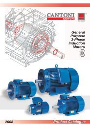
4.3 Mating the motor to a frequency converter.Standard motors powered with AC up to 400V, series Sg and Sh, manufactured by FME Indukta, have an insulationsystem making it possible to be powered through frequency converters. For heat factors, it is not recommended topower progressive Psg or PSh series motors through converters.These converters allow for adjusting the motor's rotational speed. Do not exceed the maximum rotational speeds ofthe motor listed in the following chart:Motor size2p=2 2p=4 2p=6 2p=8rev/min90 ÷112 5200 3600 2400 2000132 ÷ 200 4500 2700 2400 2000Attention: If adjusting the frequency (rotational speed) above 200% of the rated frequency, it isrecommended to use motors with external cooling and better balance of rotor.Adjustment of rotational speed, depending on the load torque, can take place only in scope presented in the graphno. 1, and the maximum load torque of induction motors with external cooling, depending on the frequency ofsupplied current, is presented in graph no. 2. Operation in orange field is dependent on kind and settings of frequencyconverter.Graph no. 1Graph no. 2OPERATING MANUAL – THREE- PHASE SQUIRREL- CAGE INDUCTION MOTORS 13/32PUBLICATION DATE: 9.05.2011 - EDITION 4
9550 ⋅ P [kW]M [Nm] =−1Analysing the formula: n [min ] notice that the increase of rotational speed, while maintaining aconstant torque, must be accompanied by an increase of power. With speeds exceeding the rated speed, theincrease of power would cause an increase of the current drawn by the motor, which causes motor overheating. Forthis reason, in rotational speed higher than the rated speed, the load torque on the shaft needs to be lowered. While<strong>operating</strong> the motor in rotational speed higher than the rated speed, pay attention to the current drawn by the motor,and make sure that it is not higher than the rated current.While the motor is operated in speeds higher that the rated speed, the level of noise and vibrations increases, andthe life span of bearings can be shorter. Attention: do not exceed the rotational speed listed in chart.A method of eliminating these unfavourable effects can be: using dU/dt filters, which smooth out the rate of output voltage, blocking the frequencies in the inverter, in which the unfavourable effects take place, change of the carrier frequency (transistor keying), adjusting other inverter parameters.The ratio of the output voltage to the frequency converter's output frequency, in the range up to the rated frequency,is constant, which is a condition of achieving constant torque on the motor's shaft. Above the rated frequency, thevoltage value is constant, which results from the voltage value of the converter's power supply. A motor, whose therated voltage when connected in a star is equal to the rated voltage of the frequency converter, can be connected ina delta. Its rated voltage will now beThis will make it possible to extend the rangeof operation with a rated torque to 86.6 Hz. The new value of the motor's rated voltage should be entered into thefrequency converter.Attention: When making the connections described above, it is recommended to consult with the supplier ofthe converter in regard to the new frequency converter settings.An example: Having a 230∆/400Y motor, connected in a star and a frequency converter with output voltage(ratio U/f=8), we can connect the motor in a delta (Un=230V) and set this parameter in theconverter (U/f=4.6). This way the adjustment range on the motor's shaft, with a constant torque, increases to86.6Hz.For example:Rated voltage ofmotorRatedfrequencyRated current Rated outputMaximaloutput400V Y (U/f=8) 50Hz 6,2A 3,0kW 3,0kW230V ∆ (U/f=4,6) 50Hz 10,7A 3,0kW 5,2kW (87Hz)Withstand voltage stress of insulation.Motors up to 400V AC have insulating system compatible with standard IEC TS 60034-17, resistant forvoltage impulses 1.35kV at the impulse rise time ≥0,8µs. When using converters without any reduction of voltageimpulses such motors are suitable for drive systems only up to 400V AC supply voltage within a restricted range ofcable length. When using filtering devices, such motors can be used for drive systems up to 690V supply voltageand without limits of cable length.Recommended is using filters on inverter output, which eliminate considerably problems with overvoltage,acoustic effects, reduce current ripples. Filters protect motor isolation and elongate time of using the motors.4.4 Defects in the work of a motor and their removal.Defects, which can be the reason of most frequent motor malfunctions, are listed in the following chart.DEFECT CAUSE SOLUTIONMotor overloadedDecrease the load.Incorrect power supply.Motor not moving or moves heavilywhen idlingIncorrect connection system.Rotor damage.Check the voltage of the powercable terminals, check the powerlead connection, check the settingon the frequency converter –remove the cause.Check the connections against thediagram supplied with the motorLook for cracked bars or end ringsOPERATING MANUAL – THREE- PHASE SQUIRREL- CAGE INDUCTION MOTORS 14/32PUBLICATION DATE: 9.05.2011 - EDITION 4
Incorrect power supply connection.Too many starts per hour.Too many starts per hour.Ventilation openings in theventilator's or console's cover maybe blocked with dirt, preventingcorrect motor ventilation.Connect the motor according to thediagram.Increase the intervals in the motoroperation, eventually decrease thenumber of switchingsIncrease the intervals in the motoroperation, eventually decrease thenumber of switchingsClean the ventilation openings andcheck for the continuity of the airflow from the motor.The gap between the core and theshifted brake armature is higherthan 0.06mm in places.Axial run-out of the brake lock'sfront in relation to the shaft's axis ishigher than 0.05mm.Brake power supply voltage too low(HZg, HYg) U
Overloaded thermal release turnsthe motor off during operation.Motor vibrates.A short circuit in the stator's windingor a short circuit to the frame (to theground).A break in the motor's connection orwinding.Incorrect connection system.Single-phase power supply.Motor overloadedIncorrect power supply.Rotor damage.A short circuit in the motor's windingor incorrect winding connection.A break in the motor's connection orwinding.Incorrect connection system.Incorrect overload range setting inthe thermal releaseSingle-phase power supply.Motor baldy aligned.Weak mounting.Unbalanced coupling.Driven appliance unbalanced.Bearings damaged.Unaligned bearings.Displaced balance weights.Unbalanced motor and coupling unitMultiphase motor operates in asingle phase.Excessive axial loosenesson the frequency converter –remove the causeFind and remove the short circuit(rewind the motor).Find and remove the break.Connect the motor correctly.Check the voltage of the powercable terminals, check the powerlead connection.Decrease the loadCheck the voltage of the powercable terminals, check the powerlead connection, check the settingon the frequency converter –remove the cause.Look for cracked bars or end ringsRemove the short circuit, removethe bad connection or rewind themotor.Find and remove the break.Connect the motor correctly.Set the overload protection correctly.Check the voltage of the powercable terminals, check the powerlead connection, check the settingon the frequency converter –remove the causeRe-align.Enforce the base.Balance the coupling.Balance the driven appliance.Replace the bearing.Re-align correctly.Balance the motor.Balance the unit.Check whether the motor has anopen circuit.Adjust the bearing or add a washerGrindingNoisy operation.Brake buzzing while switching themotor offThe ventilator rubs against thecover.The fan is hitting the cover.Looseness on the base plate.Uneven air gap.Spinning parts not balanced.Belt tension too high.Incorrect coupling of the motor withthe driven machine.A break in the brake'selectromagnet circuit.Break in the lead supplying power tothe brake.Brake's air gap has exceeded itsEliminate the friction.Clean the fan and the cover, checkthe fan's mounting on the shaft.Tighten the clamping screws.Check and correct the bracket orbearing mounting.Find and remove the mechanicaldamage (rotor, pulley, coupling,ventilator, and carefully balance).Adjust the motor orientation and belttensionReplace the bearings. Adjust themotor orientation and belt tensionReplace the electromagnet.Remove the damage.Adjust the gap.OPERATING MANUAL – THREE- PHASE SQUIRREL- CAGE INDUCTION MOTORS 17/32PUBLICATION DATE: 9.05.2011 - EDITION 4
Bearings heat up.Motor seizes up.maximum value.Power supply voltage too lowU
5. MOTOR MAINTENANCE.In order to maintain the motor in full technical efficiency, it is necessary to remove all defects noticed duringoperation on an ongoing basis.Regardless of the above, every working motor should be subjected to periodic maintenance inspections. Timeperiods between maintenances, running and major repairs, are dependent on the conditions of motor's work.ATTENTION!In order to attempt any type of work related with the motor or its elements,especially prior to taking off protective covers, prior to directly touching movingparts or parts which can be under current, unplug the motor and all additional andsupport circuits from the mains.5.1 Periodic inspections.Customary time periods are as follows:• running inspection every 6 months (for dust-laden room, every 3 months)• main inspection – once every 30 months.Running inspections – performed at thelocation of motor's installation, without adisassembly. This type of inspection can reveal aneed to subject the motor to a main inspection.Main inspections – include the followingoperations:Running inspections include the followingoperations: cleaning the motor and a visualinspection, measuring the insulation resistance ofthe winding; examining the condition of power cablesand the earthing cable; checking the tightness of all mountingand contact screws;disassembly of the motor,stator inspection,inspection of the rotor,inspection of bearings and bearingchambers;removal of condensate in motorsfeaturing drain plugs in the disksmeasurement of insulation resistance ofthe winding;inspection of the starting and protectivedevices.AFTER A MAIN INSPECTION AND ANY EVENTUAL REPAIRS OF THE MOTOR'S WINDING, CHECK THECONDITION OF THE WINDING'S INSULATION AS DESCRIBED IN CHAPTER 3.2.Additionally, in motors with brakes, inspect the brake elements. A detailed description of the brakes is included inattachment no. 5. In case of a large number of switchings, inspect the brakes more often than every 6 months.All defects noticed during the inspection should be removed, and worn out parts replaced with new ones.It is recommended to renew the protective layers.5.2 Sizes and types of bearings.Size and type of bearings used in different types of motors:S(K, L)h 90 - 6205-2Z-C3S(K, L)g 100 - 6206-2Z-C3S(K, L)g 112 - 6306-2Z-C3S(K, L)g 132 - 6308-2Z-C3S(K, L)g 160 - 6309-2Z-C3S(K, L)g 180 - 6311-2Z-C3S(K, L)g 200 on the drive side - 6311-2Z-C3 ; S(K, L)g 200 on the non-drive side - 6213-2Z-C3OPERATING MANUAL – THREE- PHASE SQUIRREL- CAGE INDUCTION MOTORS 19/32PUBLICATION DATE: 9.05.2011 - EDITION 4
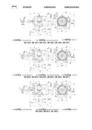
5.3 Greased the bearings.Bearings closed on both sides /type 2Z/ are filled with grease by the manufacturer which lasts for their whole lifespan. The life span of standard bearings is 25 000 hours.After the expiration of the motor's warranty it is recommended to replace the bearings for new ones.Bearings in motors with buried grease nipples in bearing brackets (fig. 6) should be greased periodically. Greasingperiods, type and amount of grease are listed in the following chart:Motor sizeAmount ofrefilled grease [g]Grease refilling period [h]n≥1500 rpm3000 rpm80 3 2500 150090 4 2500 1500100 5 2500 1500112 7 2500 1500132 10 1500 1000160 12 1500 1000180 17 1500 1000200 17 1500 1000Grease typeas specified bythe motor'sdocumentation5.4 Disassembly and assembly of the motor.Fig. 6By principle, motor disassembly should take place outside the place of its operation, in a speciallyprepared location.Tools required include a regular set of assembly tools and instruments. Prior to a correct disassembly, take off themotor pulley or the half coupling using a turnbuckle (fig. 8), remove the key (7) from the shaft extension, unscrew 4screws (5) and remove the ventilator cover (13) (fig. 7). After unscrewing 4 screws (5) which mount the bearingbrackets "P", carefully remove the rotor (1) with the bearing brackets "P" (11) and the ventilator (8) from the stator,without damaging the winding. If it is necessary, or when replacing the grease, remove both bearings (17) using aturnbuckle.Prior to removing the "P" bearing (), it is necessary to:remove the spring clip mounting the ventilator (10) and take off the ventilator (8) from the rotor's shaft alongwith the key, using a turnbuckle; remove the "P" bearing bracket (11) from the rotor's shaft (1).After completing these steps, remove the "P" bearing (17) using a turnbuckle.OPERATING MANUAL – THREE- PHASE SQUIRREL- CAGE INDUCTION MOTORS 20/32PUBLICATION DATE: 9.05.2011 - EDITION 4
Fig. 7Fig. 8Attention: For motors with a gripped bearing fig. 9 and 10, (also regards vertical motors), prior to the disassembly ofthe bearing it is necessary to:• remove 3 screws mounting the bearing cover (4) and remove the rotor's spring clip (3) (this also regardsmotors with a closed bearing chamber - see fig. 9)• remove the spring clip in the bearing brackets (3) and rotor (4) (this also regards motors with a openbearing chamber – see fig. 10).OPERATING MANUAL – THREE- PHASE SQUIRREL- CAGE INDUCTION MOTORS 21/32PUBLICATION DATE: 9.05.2011 - EDITION 4
Fig. 9 Fig. 10In case of a motor with a brake (fig. 11), prior to the disassembly of the motor it is necessary to disassemble thebrake (19).In case of motors with an external ventilation system (fig. 12), external ventilation (10) is disassembled along withthe cover.Fig. 11OPERATING MANUAL – THREE- PHASE SQUIRREL- CAGE INDUCTION MOTORS 22/32PUBLICATION DATE: 9.05.2011 - EDITION 4
Fig. 12Fig. 13 Fig. 14OPERATING MANUAL – THREE- PHASE SQUIRREL- CAGE INDUCTION MOTORS 23/32PUBLICATION DATE: 9.05.2011 - EDITION 4
Disassembly of the motor's terminal box is done in accordance with drawing no. 13. Depending on the type ofmotor, following terminal box settings are available:• custom version (fig. 14)• version with an HPS brake (fig. 15)• version with an HZG brake (fig. 16)Fig. 15 Fig. 16Motor assembly should be done in reverse order.After a correct assembly, the rotor should freely turn when spinning the shaft neck <strong>manual</strong>ly.6. LIST OF REPLACEMENT PARTS.• Rotor set• Bearing bracket N - machining• Flange bracket - machining• Gasket ring (V-ring)• Spring washer• Bearing N• Bearing cover - machining• Cover's felt ring• Bearing bracket P - machining• Bearing P• Rotor's stopper ring• Ventilator• Ventilator cover• Terminal box setOPERATING MANUAL – THREE- PHASE SQUIRREL- CAGE INDUCTION MOTORS 24/32PUBLICATION DATE: 9.05.2011 - EDITION 4
7. ATTACHMENTS.Attachment no. 1 Throttle range of cable glands.Gland size Throttle range in[mm]M12 3.5 ÷ 7M16 4.5 ÷ 10M20 7 ÷ 13M25 9 ÷ 17M32 11 ÷ 21M40 19 ÷ 28Attachment no. 2. Torque values for the tightness of nuts and screws.Thread M 4 M 5 M 6 M 8 M10 M12 M16Torquevalue inMin. 0.8 1.8 2.7 5.5 9 14 27[Nm] Max. 1.2 2.5 4 8 13 20 40Attachment no. 3 Minimal earthing or protective lead profiles.Live lead profile S [mm 2 ] Earthing or protective conductor profile[mm 2 ]S ≤ 25S25 < S ≤ 50 25S > 500.5 SOPERATING MANUAL – THREE- PHASE SQUIRREL- CAGE INDUCTION MOTORS 25/32PUBLICATION DATE: 9.05.2011 - EDITION 4
Attachment no. 4. Standard motor terminal connection diagrams.1. 3-phase single-speed motors:Connection in a ∆Connection in a Y2. 3-phase dual-speed general use motors (single-winding), for example, 2p=4/2, 8/4:GEAR 1 2p=4(8)(12)Connection in a ∆GEAR 2 2p=2(4)(6)Connection in a YY3. 3-phase dual-speed motors (double-winding), for example 2p=6/4, 8/6:GEAR 1 2p=4(8)(12)Connection in a YGEAR 2 2p=2(4)(6)Connection in a Y4. 3-phase dual-speed ventilator motor (single-winding), for example 2p=4/2W, 8/4W – motor marking ending in„W":GEAR 1 2p=4(8)(12)GEAR 2 2p=2(4)(6)Connection in a YConnection in a YY5. 3-phase dual-speed motors (nine terminals), for example 2p=4/2, 8/4:Connection in a ∆ Connection in a Y Connection in a YYOPERATING MANUAL – THREE- PHASE SQUIRREL- CAGE INDUCTION MOTORS 26/32PUBLICATION DATE: 9.05.2011 - EDITION 4
ATTENTION! Do not supply power to the external cooling or the brake using the frequency converter.6. 3-phase single-speed motors:a) with an AC brake b) with an independently powered AC brakec) with a DC brake d) with an independently powered DC brake7. Diagram of supplying power to external cooling – in standard versions, motors have a separate external coolingbox.Motor mechnical size 90÷112 Motor mechnical size 132÷180OPERATING MANUAL – THREE- PHASE SQUIRREL- CAGE INDUCTION MOTORS 27/32PUBLICATION DATE: 9.05.2011 - EDITION 4
Attachment no. 5. Disk brakes type H, HPS and H(Z,Y)g.1. Construction and principle of operationa) type H brakeThe electromagnetic DC brake type „H” consists of3 main units: the electromagnet (1), the armature(2) and the cast iron fan (3).Switching on the electromagnet (1), supplying directcurrent from the motor through the rectifying circuitcauses the armature (2) to be shifted, with asimultaneous release of the fan (3) and the brake isreleased.Switching off the electromagnet (1) causes thearmature to be moved (2) through the springs untilthe torque is created and the brake lining is pressedagainst the ventilator. The brake is immobilized (halted).1094251a3768b) HPS type brakeThe construction of the brake is presented in thedrawing. When no current is fed to the coil (2), thebrake disk (5) with friction lining is pressed by thearmature (4) to the mounting disk (5) or directly tothe surface of the given device with the force of thesprings (8), the brake is then in the 'on' state (it isbraking). The braking torque is transferred by the13 12brake disk (5) to the gear (6) located on the motor's11 9 1058shaft, or the device mated to the brake, protected7from axial displacement with a spring clip. The6torque size can be adjusted by screwing in the nut(3) or reducing the number of springs.Direct current fed to the electromagnet's winding (2),15432through its excitation, causes the armature to beshifted (a=0), at the same time eliminating thepressure of the springs on the armature and thebrake disk (5). The brake is released.If no voltage is present or a damaged electromagneta1in the brake with a hand-release lever, it is possible to release the brake by moving the lever. Releasing thepressure on the lever causes its return and repeated braking. Adjustment screws (11) set the distance between theelectromagnet and the mounting disk (5) or the motor's bearing brackets, regulating the size of the air gap. HPStype brakes are mounted to the motor's bearing brackets using clamping screws (10).The air gap „a” is factory set to the rated value; as the brake disk gets worn, the depth of the clamping screws' drive(11) is increased by the size of performed adjustments.H(Z,Y)g type brakeThe brake disk (7) has two friction linings (8) locatedHZgHZYgbetween the mounting disk (9) and the armature (2).In brakes designed to be mounted directly to themotor's bearing bracket, or to the mated device, itserves the role of the second friction surface for thebrake disk. Force caused by the pressure of thesprings (4) acts on the armature, which istransferred to the brake disk (7) causing it to rubagainst the armature and the mounting disk, causing9 3 12 4S11 6 13 10 15 14a braking torque this way. The size of the torque canbe changed by reducing the number of springs.Alternating current fed to the electromagnet'swinding (5) causes the S = 0 armature to be shifted,eliminating the pressure of the springs on the8 1 7 2 5S1armature, releasing the brake. In case of brakes with a lever (14) is it possible to <strong>manual</strong>ly release the brake bymoving the lever; releasing the pressure causes it to automatically return to the starting position and repeatedbraking.OPERATING MANUAL – THREE- PHASE SQUIRREL- CAGE INDUCTION MOTORS 28/32PUBLICATION DATE: 9.05.2011 - EDITION 4
Adjustment screws (3) screwed into the bearing ring (6) set the distance of the electromagnet to the face surface ofthe mounting disk (motor's bearing bracket), setting the air gap S value.Brakes are clamped using 3 screws (13) spaced every 120 degrees, and 3 screws (10) connect the brake'selements with the mounting disk. In case of a brake without the mounting disk, its assembly is done using 6 screwsspaced every 60 degrees.A rubber band (12), sealing the brake is placed on the brake's cover (11), which has openings allowing for adjustingthe air gap. In new brakes, the air gap is set to the value S nom. As the brake disk's friction lining gets worn withuse, its value cannot exceed the value of S max. Exceeding the maximum value with reduce the braking effect bylowering the braking torque which can cause damage to the electromagnet, which may fail to shift the armature andrelease the brake due to the exceeded maximum value of the air gap. Therefore it is necessary to adjust it bysetting the s nom value.S nom.. Maximum friction lining wear is 3 mm per side, which allows for multiple adjustments of the air gap. As thewear of the lining increases, the depth of clamping screws drive also increases (10) and (13), and with worn outlining it can reach 6 mm.2. Assembly and disassembly of the brakea) type H brakeA condition of correct functioning of the brake is to maintain perpendicularity of the surface on which the brakerests, in relation to the motor's axis.Mounting the brake on the motor with an adapted bearing bracket and motor's shaft takes place using threeclamping screws (4), spaced 3x120°. Next, the shaft is put on the central spring (5), which is rested on the bearing'sinner ring. Tightly screw in the clamping screw (7) to the motor's shaft and put on the fan (3), which is led on theinternal diameter and a key channel.Put the special washer (6) on the fan (3) and the clamping screw (7), and tighten the nut self-locking (8) until a 0.2air gap is set (see chart 1).Put on the gasket ring (9) between the frame (electromagnet (1)) and armature, than cover the brake with themotor's cover.Chart 1TYPE H-63 H-71 H-80 H-90 H-100 H-112 H-132 H-160rated gap „a” 0.2 ±0,05 0.2 ±0,05 0.2 ±0,05 0.2 ±0,05 0.2 ±0,1 0.2 ±0,1 0.2 ±0,1 0.2 ±0,1b) HPS type brakeBrakes are very simple to assemble. Mount the gear (6) on the shaft and secure from axial displacement with aspring clip. After putting the brake disk (5) on the gear, mount the brake using clamping screws (10) to the motor'sbearing cover, mounting plate (7) or wall of the mated device. If the brake has blocking elements (14), they shouldbe removed after mounting the brake. Check the air gap „a” value, which should be equal to the „a nom” value listedin chart 2. In case of finding a discrepancy, adjust the gap as described in paragraph 3. Put on the brake cover.Disassembly should be done in reverse order.Chart 2TYPE HPS06 HPS08 HPS10 HPS12 HPS14 HPS16 HPS18 HPS20 HPS25a nom. 0.2 ±0,05 0.2 ±0,05 0.2 ±0,05 0.3 ±0,05 0.3 ±0,05 0.3 ±0,05 0.3 ±0,05 0.3 ±0,05 0.3 ±0,05a max. 0,5 0,5 0,5 0,7 0,8 1,0 1,0 1,2 1,4c) H(Z,Y)g type brakeH(Z,Y)g brakes are very simple to assemble. Mount the gear (1) on the shaft and secure from axial displacementwith a spring clip. After putting the brake disk (7) on the gear, mount the brake using clamping screws to the motor'sbearing bracket or wall of the mated device. Use cast iron or steel as the friction surface. If case of difficultiescreating a friction surface on the mated device, use a mounting plate (9).Check the correctness of assembly, the air gap value, which guarantees a correct work of the brake; connect thebrake to the mains, or a mated electric motor.OPERATING MANUAL – THREE- PHASE SQUIRREL- CAGE INDUCTION MOTORS 29/32PUBLICATION DATE: 9.05.2011 - EDITION 4
Disassembly of the brake should be done in reverse order.3. Electric connection systema) H type brake and HPS type brakeWhen the DC brake needs to be connected to an AC source, two rectifying circuits are used. The attachable coil ofthe brake's electromagnet circuit can be detached on the direct or alternating current side.- SWITCHING OFF ON THE ALTERNATING CURRENT SIDEW~ A C = D CBRAKEWhen switching off the voltage, the magnetic field causes that the coil's current flows through the rectifying diodeand falls slowly. Magnetic field is reduced gradually, which causes a lengthened period of the brake's operation,which means a delayed increase of the braking torque. If the working time is insignificant, the brake should beconnected on the alternating current side, since no other protection for the coil and the contacts is needed. Whenbeing switched off, supply circuits act as unidirectional diodes.- SWITCHING OFF ON THE DIRECT CURRENT SIDE~ACW= DCBRAKECoil's current is broken between the coil and the power supply (rectifying) circuit. Magnetic field is reduced veryquickly, brake's operation time is short, in consequence, the braking torque increases quickly. When tripping on theside of direct current in the coil, high peak voltage is generated causing faster wearing out of contacts due tosparking. In order to protect the coil against peak voltage and to protect the contacts from excessive wear, therectifying circuits have protection allowing to connect the brake on the direct current side.b) H(Z,Y)g type brakeConnecting the brake is done according to the above drawing.L1L2L3BRAKE4. Adjustment of the air gapa) HPS type brakeAir gap „a” increases as a result of the brake disk (5) wearing out. The appropriate initial „a nom.” value of the gapcan be restored by screwing in the adjustment screws (11) into the frame (1). When adjusting, loosen the clampingscrews (10), use a gap gauge inserted between the armature and the frame by screwing in the adjustment screws(11), set the air gap to the rated value. Tighten the clamping screws (10) – total stiffening of the attachment point isachieved by countering it with adjustment screws, meaning by unscrewing them to the limit with the mounting plateof the surface of the mated device.b) H(Z,Y)g type brakeOPERATING MANUAL – THREE- PHASE SQUIRREL- CAGE INDUCTION MOTORS 30/32PUBLICATION DATE: 9.05.2011 - EDITION 4
Correct work of the brake is ensured when the S and S1 gaps have correct values.Gap values:S nom = 0.4 mm S max = 1.4 mm S 1 = 2 mmIn case of exceeding the listed S max value, adjust the air gap immediately. In order to do this:- remove the rubber band (12),- loosen the screws (10) and (13) clamping the brake, unscrewing them half a turn,- through openings in the cover (11), tighten the adjustment screws (3) to the bearing ring??? (6) by about 2 mm2mm- place a gap gauge with thickness of S nom +/- 0.05 mm in the gap between the electromagnet's core (5) and thearmature (2).- using clamping screws, press the core to the armature so that the gap gauge can be taken out with little resistanceand with the same resistance insert it in gaps every 120 degrees from the place of initial measurement,- unscrew adjustment screws so they rest on the mounting plate or the motor's bearing bracket, or another mateddevice,- tighten the brake's clamping screws and check the size of gap S,- in brakes with a <strong>manual</strong> release lever (14), self-locking nuts (15) must be set so that their distance from thearmature plate S 1=2mm is maintained when the armature is shifted, i.e. when S = 0.5. Periodic inspectionsEach brake being used should be inspected at least once a year.The work period, after which an inspection is required, depends on the intensity of motion and are listed inregulations for individual devices, for example for crane devices.During the inspection (after removing the rubber band and the brake cover):- remove dirt which has collected in the brake's interior,- check the size of the gap using a gap gauge:a) type H brake; adjust the air gap to the value listed in chart 1, using a self-locking nut (8).The adjustment can be performed many times, until the brake lining is worn out. When the brake lining iscompletely worn out, replace the armature with the brake lining (2) for new ones;b) HPS type brake; check the gap in accordance with paragraph 4 a) and chart 1; c) type H(Z,Y)g brake; S1 betweenthe armature and castellated nuts. The sum of the measured gaps S + S 1 (in braking state) should amount to 1.8-2mm; adjust if needed;- perform few braking tests, check the effectiveness of braking.If significant decrease in the effectiveness of braking is noticed in relation to the initial state, the brake should bedisassembled in order to check the condition of friction lining, tracks and springs.When the brake disk achieves its maximum wear, it should be replaced for a new one (the lining's working surfacehas levelled out with the aluminium bearing element of the brake disk). When replacing the brake disk, make surethat the friction surface of the disk, the armature and the elements mated with friction lining are free from greaseand oil.If the brake, despite correct assembly and appropriate adjustment, does not work:- the electromagnet has been damaged – the coil burned out, power lead damaged- the rectifying circuit (installed in the motor's terminal box or machine's control cabinet) has been damaged- check the correctness and quality of electric connections- replace damaged elements for new ones.Check the electric units mentioned above and replace damaged ones.Attachment no. 6. External cooling parameters.OPERATING MANUAL – THREE- PHASE SQUIRREL- CAGE INDUCTION MOTORS 31/32PUBLICATION DATE: 9.05.2011 - EDITION 4
EXTERNAL COOLING FAN SPECIFICATIONMotor sizeRatedvoltageFrequency Rated current Input power Speed Air flow Noise level[V] [Hz] [A] [W] [min -1 ] [m 3 /min] [dB]90/100/112 1 x 230 50/60 0,23/0,21 32/31 2800/3100 5,40/6,60 50/55132/160/180 1 x 230 50/60 0,24/0,27 56/60 2100/1900 24,0/21,8 57/55Type ofprotectionImpedanceprotectionThermalprotection• surrounding temperature from -20 to +80[°C],• installation height up to 1000 [m] above sea level,• life span – 50 000 h in 25°C temperature,• insulation class B,• motor protection• – thermal protection – automatic motor switch-off after achieving winding temperature of 110°C, autom aticswitch-on after the temperature decreases to 70°C,• – impedance protection – motor can operate in abnormal conditions, such as rotor lockup.• protection rating IP 55,• ball bearings.OPERATING MANUAL – THREE- PHASE SQUIRREL- CAGE INDUCTION MOTORS 32/32PUBLICATION DATE: 9.05.2011 - EDITION 4