
You also want an ePaper? Increase the reach of your titles
YUMPU automatically turns print PDFs into web optimized ePapers that Google loves.
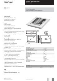
luxCONTROL<strong>DALI</strong> <strong>manual</strong>
.cIntroduction: <strong>DALI</strong> standardIntroduction: <strong>DALI</strong> standardHistoryThe agreement by the lighting industry to adopt a common protocol for digital addressable control of luminaires hasopened up a virtually unlimited number of options for regulating artificial lighting in all applications. This commonprotocol is the <strong>DALI</strong> protocol (Digital Addressable Lighting Interface), which has now been internationally standardisedthrough the IEC.With the right choice of individual <strong>DALI</strong> components an extremely wide range of requirements can be met, fromoperating the lighting system from a simple light switch to lighting management systems for entire office complexeswith thousands of light sources. The new standardisation means that there are no longer any restrictions on theapplication of this technology. Any light source, including incandescent lamps, fluorescent lamps, high-intensitydischarge lamps and even LEDs, can be controlled irrespective of whether they are installed in an office, a restaurantor a street light.The <strong>DALI</strong> system is based on simplicity of operation. However the demands on electrical system designers andelectricians have increased enormously.The purpose of this technical <strong>manual</strong> is to describe how the <strong>DALI</strong> system components offered by <strong>Tridonic</strong> operate andillustrate their functionality by looking at how they can be used in actual practice.<strong>DALI</strong> stands for “Digital Addressable Lighting Interface” and is an interface protocol for digital communication betweenelectronic lighting equipment (electronic ballasts, transformers, etc.).The <strong>DALI</strong> standard was developed by <strong>Tridonic</strong> together with renowned manufacturers of operating and controlequipment. Today, these manufacturers belong to the <strong>DALI</strong> Activity Group which promotes the use of <strong>DALI</strong> andsafeguards its further development.The <strong>DALI</strong> standard was defined in EN 60929 Annex E until 2009 but is now defined in IEC 62386. This standard alsodescribes the differences between the various types of device. As a result, long-term compatibility amongmanufacturers is guaranteed and the <strong>DALI</strong> standard is ensured a secure future. In addition, compatibility betweenproducts from different manufacturers is supported by a test procedure standardised by the <strong>DALI</strong> Activity Group. Allproducts that carry the logo of the <strong>DALI</strong> Activity Group have successfully passed this standardised test. <strong>Tridonic</strong>products meet these requirements in full.<strong>DALI</strong> Manual | 08-2013 | en4 / 93
.cIntroduction: <strong>DALI</strong> standardPositioning of <strong>DALI</strong><strong>DALI</strong> is not a new system for building control such as LON, KNX and other building management systems but a usefuladdition for the practical application of lighting controllers. <strong>DALI</strong> provides ideal support for building control systems andenables each light source to be individually addressed. Even small installations in which a building control systemwould not be economical need not forego the convenience of digital technology. <strong>DALI</strong> can be used in such installationsas an independent lighting management system.Digital technology has taken over from analogue technology in lighting control systems because of the universalapplication of <strong>DALI</strong> units and their reliable control....<strong>DALI</strong> Manual | 08-2013 | en7 / 93
.c<strong>DALI</strong> controllers of comfortDIM product seriesOverview of <strong>DALI</strong> controllers and <strong>DALI</strong> control gear<strong>DALI</strong> controllers of comfortDIM product seriesThe unique comfortDIM concept is the basis for extremely user-friendly lighting solutions with enormous flexibility forfuture expansion. It uses the <strong>DALI</strong> protocol (Digital Addressable Lighting Interface). This is a standardised protocol thatensures maximum investment protection and future-proofing. It also guarantees security of planning and high levels offlexibility even after set-up.<strong>DALI</strong> Manual | 08-2013 | en8 / 93
.c<strong>DALI</strong> controllers of comfortDIM product seriesTable: Functional overview comfortDIM<strong>DALI</strong> GC<strong>DALI</strong> SC<strong>DALI</strong> MC<strong>DALI</strong>TOUCH-PANEL02<strong>DALI</strong> SQMx-touch-PANEL 02<strong>DALI</strong>MSensor 02Manual group / scene controlGroups and scenes can be easilyswitched and dimmed with the groupand scene control modules.Multi-functional controlThese control modules ensuremaximum flexibility. The inputs andbuttons can be freely programmed fora wide range of functions.Automatic scene control (sequence)Predefined lighting scenes can beeasily combined into a self-executingsequence.Automatic color control (sequence)Predefined light colours can be easilycombined into a self-executingsequence.Time-controlled daily processes(scheduler)Predefined scenes, sequences orcolours can be controlled or recalledvia a real-time clock.Automatic daylight and presencecontrol<strong>DALI</strong> lighting controls supplementedwith a sensor module enableenergy-efficient solutions to beprovided.Remote control of the <strong>DALI</strong> circuitFunctions can be controlled from aninfrared remote control.Convenient operation andprogrammingSimple set-up of the <strong>DALI</strong> circuit andconvenient operation of the controlfunctions.<strong>DALI</strong> Manual | 08-2013 | en9 / 93
.c<strong>DALI</strong> controllers of comfortDIM product seriesConvenient configuration with a PC<strong>DALI</strong> systems can be easily configuredby means of an interface module andPC software. Even complex systemscan be easily set up.Manual color temperature controlTunable white devices can becontrolled.<strong>DALI</strong> power supply <strong>DALI</strong> PS / <strong>DALI</strong> PS1 / <strong>DALI</strong> PS2<strong>DALI</strong> PS, <strong>DALI</strong> PS1 and <strong>DALI</strong> PS2 are <strong>DALI</strong> power supply modules with a rated current of 200 mA (240 mA in thecase of <strong>DALI</strong> PS2). The modules differ in their casing design; <strong>DALI</strong> PS and <strong>DALI</strong> PS2 are suitable for installation inswitching cabinets; <strong>DALI</strong> PS1 is suitable for installation in suspended ceilings or cavities.<strong>DALI</strong> group controllers<strong>DALI</strong> GC / GC-ATwo lighting groups can be controlled with the group controller (ON/OFF/DIM). Set-up (addressing) and assignment tothe <strong>DALI</strong> groups can be performed by means of a simple switch sequence. In the case of the GC-A version,configuration via the switches is disabled to prevent unintentional reprogramming. The compact design enables theunit to be installed in a standard switch box.<strong>DALI</strong> scene controllers <strong>DALI</strong> SC / SC-AThe scene controller enables four lighting scenes to be programmed and recalled.<strong>DALI</strong> Manual | 08-2013 | en10 / 93
.c<strong>DALI</strong> controllers of comfortDIM product seriesThe scene controller enables four lighting scenes to be programmed and recalled.In the case of the SC-A version, configuration via the switches is disabled to prevent unintentional reprogramming.The compact design enables the unit to be installed in a standard switch box.<strong>DALI</strong> multicontroller<strong>DALI</strong> MC<strong>DALI</strong> MC has 4 inputs, the functions of which can be freely edited. Via the settable switching modes (short, long press;toggle; relay mode) a maximum of two options can be assigned to each input, of which one function can be activated ineach case. Customer-specific programming is possible via the masterCONFIGURATOR (see Reference list)configuration software. The compact design enables the unit to be installed in a standard switch box.<strong>DALI</strong> TOUCHPANELThe <strong>DALI</strong> TOUCHPANEL 02 has selectable control panel functions for <strong>manual</strong> control of <strong>DALI</strong> lighting groups and<strong>DALI</strong> lighting scenes. Customer-specific programming is possible via the masterCONFIGURATOR (since version 2.6)(see Reference list) .<strong>DALI</strong> x/e-touchPANEL 02The x/e-touchPANEL 02 with its 7 inch colour touch screen is a lighting management system for up to 128 <strong>DALI</strong> units.The x/e-touchPANEL 02 contains user-friendly application software with a mode optimised for RGB colour lightingmanagement.<strong>DALI</strong> Manual | 08-2013 | en11 / 93
.c<strong>DALI</strong> controllers of comfortDIM product series<strong>DALI</strong> sequencer module<strong>DALI</strong>-SQMThe sequencer module sends broadcast-addressed scene calls at user-defined intervals (up to 16 different scenes).The factory-setting is that a sequence comprises 8 scenes. When the last scene is reached the cycle starts again fromthe beginning.<strong>DALI</strong> MSensor 02The <strong>DALI</strong> MSensor 02 is a <strong>DALI</strong>-based sensor with ambient light control and presence detection. The <strong>DALI</strong> MSensor02 also has a receiver for infrared remote control. There are versions for installation in luminaires, ceilings and boxesand also for surface mounting.<strong>DALI</strong> RC and IR smart ControllerThese two remote controls extend the functionality of the <strong>DALI</strong> MSensor 02.With the user-friendly <strong>DALI</strong> RC remote control it is also possible to perform all the basic functions of the <strong>DALI</strong> MSensor<strong>DALI</strong> Manual | 08-2013 | en12 / 93
.c<strong>DALI</strong> controllers of comfortDIM product seriesWith the user-friendly <strong>DALI</strong> RC remote control it is also possible to perform all the basic functions of the <strong>DALI</strong> MSensor02.<strong>DALI</strong> USBThe <strong>DALI</strong> USB interface module enables the <strong>DALI</strong> installation to be set up and parametrised with the aid of a PC.<strong>Tridonic</strong> offers therefore the software masterCONFIGURATOR (see Reference list) to make it easier to put evencomplex <strong>DALI</strong> installations into operation.<strong>DALI</strong> RS232 Interface PS/SThe <strong>DALI</strong> RS232 Interface PS/S combines a <strong>DALI</strong> interface module and a power supply module in one and the samedevice. The rated current of the power supply is 240 mA. Via the RS232 interface it is possible to put the <strong>DALI</strong> systeminto operation and to set its parameters. During normal operation the interface can be used for service purposes. TheRS232 interface is accessed via an RJ45 socket. An optional connecting cable from the RJ45 socket to an RS232 plugis available as an accessory.Additional adapters (to USB for example) are available from various manufacturers....<strong>DALI</strong> Manual | 08-2013 | en13 / 93
.c<strong>DALI</strong> interface modules<strong>DALI</strong> interface modules<strong>DALI</strong> DSI / DSI IIThe <strong>DALI</strong> DSI converter converts <strong>DALI</strong> commands into DSI signals so that DSI-based units can be integrated in <strong>DALI</strong>lighting control systems.<strong>DALI</strong> Somfy animeo interfaceWith this interface Somfy animeo IB+ motor controllers can be integrated in the <strong>DALI</strong> circuit. The <strong>DALI</strong> Somfy animeointerface can control up to four blinds independently. The blind positions (height and angle) are stored like lightingscenes. The lighting and the blind positions can be stored under one and the same scene.<strong>DALI</strong> 3-RM-CThe <strong>DALI</strong>-3-RM-C relay module controller enables up to 3 standard contactors (24 V DC) to be controlled so thatdifferent loads can be switched via <strong>DALI</strong> commands.<strong>DALI</strong> RMThe <strong>DALI</strong> RM relay module controller enables a contactor (12/24 V or 230V ) to be controlled so that different loadsDCACcan be switched via <strong>DALI</strong> commands.<strong>DALI</strong> Manual | 08-2013 | en14 / 93
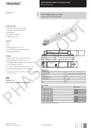
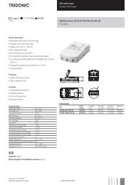
.c<strong>DALI</strong> devices<strong>DALI</strong> devicesElectronic LED control gearLCAU 2x020/0048 L0x0 one4allLCAU 2x020/0048 L0x0 one4all control gear is digital dimmable electronic control gear for PREMIUM modules (SLEand DLE). LCAU 2x020/0048 L0x0 onel4all control gear offers control options via <strong>DALI</strong>, DSI and switchDIM. Thecontrol gear supports <strong>DALI</strong> Device Type 8 for tunable white. Colours can be set via xy coordinates or via the colourtemperature. There are 16 scenes (predefined colour temperatures) preprogrammed in the control gear. These can bereprogrammed with the aid of the masterCONFIGURATOR.LCAI ECO one4all, C003. K350The LED control gear in the LCAI ECO one4all series are dimmable constant current devices with adjustable outputcurrents. There are built-in versions (Linear and Compact) and remote versions (Compact with tool-less strain relief).LCAI ECO one4all has the option of control via <strong>DALI</strong>, DSI or switchDIM and automatically adjusts to the control signal.The control gear has various functions that can be set via <strong>DALI</strong>. Details can be found in the product data sheet or inthe <strong>manual</strong>.LED control gear C003LED control gear C003 has three independent output channels for dimming light emitting diodes with 24 V.<strong>DALI</strong> Manual | 08-2013 | en15 / 93
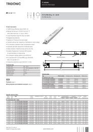
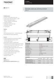
.c<strong>DALI</strong> devicesLED control gear K350LED control gear K350 is a constant current device for 350 mA LEDs and has three independent output channels.Electronic Fluorescent control gearPCA EXCEL one4all xitec IIPCA EXCEL one4all lp xitec II and PCA ECO lp xitec II are digital dimmable electronic control gear for fluorescentlamps. PCA EXCEL one4all lp xitec II has the option of control via <strong>DALI</strong>, DSI, switchDIM or SMART and automaticallyadjusts to the control signal.It also has a large number of intelligent functions and is therefore suitable for a wide range of applications. PCA ECO lpxitec II has the option of control via <strong>DALI</strong>, DSI, switchDIM and SMART and is designed for use in building managementsystems.PCA ECO lp xitec IIPCA ECO lp xitec II is digital dimmable electronic control gear for fluorescent lamps.PCA ECO lp xitec II has the option of control via <strong>DALI</strong>, DSI, switchDIM and SMART and is designed for use in buildingmanagement systems.<strong>DALI</strong> Manual | 08-2013 | en16 / 93
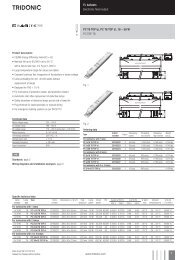
.c<strong>DALI</strong> devicesElectronic HID control gearPCIS outdoor DIM B011Very durable HID ballasts designed for outdoor applications. The Interface of the PCIS outdoor DIM B011 ballastsenables <strong>DALI</strong>, DSI and StepDIM functionality. Depending on the used lamp these ballasts can dim down to 40% tosave energy. Fixed output HID ballast with <strong>DALI</strong> / DSI interface.Electronic transformersTE one4allThe TE one4all is an electronic safety transformer for low-voltage halogen lamps. It enables low-voltage halogen lampsto be integrated directly in the <strong>DALI</strong> circuit and can also fade them up and down.TE-DC 2 one4allThe TE DC 2 one4all is an electronic safety transformer for low-voltage halogen lamps. It enables low-voltage halogenlamps to be integrated directly in the <strong>DALI</strong> circuit and can also fade them up and down.<strong>DALI</strong> Manual | 08-2013 | en17 / 93
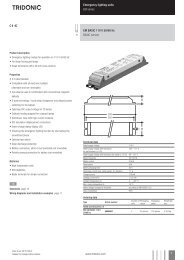
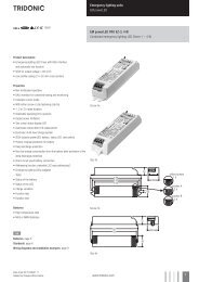
.c<strong>DALI</strong> devicesPhase dimmers<strong>DALI</strong> PCD 300 one4all<strong>DALI</strong> PCD 300 one4all is a digital leading-edge and trailing-edge phase dimmer for ceiling installation.They enable equipment such as electronic or magnetic transformers for low-voltage halogen lamps or incandescentlamps to be integrated in a <strong>DALI</strong> system.Connected load for <strong>DALI</strong> PCD 300 one4all: 30 VA – 300 VA.<strong>DALI</strong> PCD/S<strong>DALI</strong> PCD/S is a digital leading-edge and trailing-edge phase dimmer for mounting in switching cabinets.They enable equipment such as electronic or magnetic transformers for low-voltage halogen lamps or incandescentlamps to be integrated in a <strong>DALI</strong> system.Connected load for <strong>DALI</strong> PCD/S: 40 VA – 1000 VA.LED and Fluorescent control gear for emergency lightingEM PRO EZ-3LED emergency control gear for a wide range of fluorescent lamps with <strong>DALI</strong> interface and automatic test function.<strong>DALI</strong> Manual | 08-2013 | en18 / 93
.cMiscellaneousMiscellaneous<strong>DALI</strong> RepeaterThe <strong>DALI</strong> Repeater is an amplifier module for refreshing the <strong>DALI</strong> signal. With the <strong>DALI</strong> Repeater it is possible toincrease the maximum length of the <strong>DALI</strong> control line from 300 m to 600 m....<strong>DALI</strong> Manual | 08-2013 | en20 / 93
.ccomfortDIM product series in detailcomfortDIM product series in detailThis chapter provides details of the various comfortDIM products. The topics covered here include functions,connections and programming. For further information on the products please refer to the data sheets and theinstallation instructions.<strong>DALI</strong> power supply<strong>DALI</strong> PS / PS1/ PS2<strong>DALI</strong> PS, <strong>DALI</strong> PS1 and <strong>DALI</strong> PS2 are <strong>DALI</strong> power supply modules with a rated current of 200 mA or 240 mA (<strong>DALI</strong>PS2). The modules differ in their casing design; <strong>DALI</strong> PS and <strong>DALI</strong> PS2 are suitable for installation in switchingcabinets; <strong>DALI</strong> PS1 is suitable for installation in suspended ceilings or cavities.The interface of a <strong>DALI</strong> ballast needs a maximum of 2 mA; for 64 individual addresses this means a current of 128 mA.The remaining 72 mA (or 112 mA in the case of <strong>DALI</strong> PS2) can be used for supplying <strong>DALI</strong> control modules withouttheir own power supply (<strong>DALI</strong> GC, <strong>DALI</strong> SC etc.).<strong>DALI</strong> PS2 Standby<strong>DALI</strong> PS2 Standby also has a built-in relay contact. To reduce standby losses, the built-in relay disconnects theballasts from the power supply as soon as all the luminaires have been switched off.As soon as the <strong>DALI</strong> PS2 Standby detects that all the luminaires have been switched off it changes to standby modeafter a user-definable delay and controls a built-in relay. With the aid of this relay the connected units can bedisconnected from the power supply via a contactor. Only the <strong>DALI</strong> control modules are then still in the <strong>DALI</strong> circuit.As soon as a <strong>DALI</strong> control module sends a “Light ON” command the <strong>DALI</strong> PS2 Standby reverts to normal operatingmode and connects the units back to the power supply. The parameters of the <strong>DALI</strong> PS2 Standby, such as delay,monitoring interval etc. can be set using the masterCONFIGURATOR configuration software (V1.12 or higher) (seeReference list).<strong>DALI</strong> Manual | 08-2013 | en21 / 93
.c<strong>DALI</strong> power supplyFigure: Delay and monitoring intervals( 1 ) ( 2 ) ( 3 ) ( 4 ) ( 5 )Status request forthe units from the<strong>DALI</strong> PS2 StandbyPowerSupplydetects allunits offSwitch-off delayexpires(parameter: Switchoff delay)Power Supplyswitches to standbymode (relay isopened)"ON" command from a controlmodule; Power Supply leavesstandby mode (relay closes)...<strong>DALI</strong> Manual | 08-2013 | en22 / 93
.c<strong>DALI</strong> group controllers: <strong>DALI</strong> GC & GC-A<strong>DALI</strong> group controllers: <strong>DALI</strong> GC & GC-ADescription<strong>DALI</strong>-GC is a module that enables dimming commands to be sent to two groups (groups A and B) on the <strong>DALI</strong> circuit.Any standard momentary switch can be connected to the module. Its compact design means that <strong>DALI</strong>-GC can beinstalled together with the standard momentary switches in a flush-mounted box, so set-up of the <strong>DALI</strong> circuit can bedecentralised. Either individual switches or UP/DOWN switches can be used for controlling the groups. The controlledgroups are set on a rotary switch on the module.The <strong>DALI</strong> GC module is multi-master-compatible so several control modules can be used in a <strong>DALI</strong> circuit. It is alsopossible to address and group simple <strong>DALI</strong> circuits with the aid of <strong>DALI</strong>-GC.<strong>DALI</strong>-GC-A is similar to <strong>DALI</strong>-GC. The only difference is that the programming mode is not activated in <strong>DALI</strong>-GC-A.This prevents the <strong>DALI</strong> units from being reprogrammed unintentionally via the switches.ConnectionThe <strong>DALI</strong>-GC switch module is connected directly to the <strong>DALI</strong> control line and does not need a separate power supply.It is powered via the <strong>DALI</strong> circuit (current draw = 6 mA). It can be connected to the <strong>DALI</strong> circuit with either polarity.Either single momentary switches or UP/DOWN momentary switches can be used for controlling a group. If a singleswitch is used the UP/DOWN connections are simply connected in parallel. It is also possible to operate the twogroups (A and B) with different types of momentary switch; for example group A with UP/DOWN switches and group Bwith a single switch.Figure: <strong>DALI</strong>-GC momentary switch connectionSingle switch connectionUP/DOWN switch connection<strong>DALI</strong> Manual | 08-2013 | en23 / 93
.c<strong>DALI</strong> group controllers: <strong>DALI</strong> GC & GC-A½ CAUTION!The <strong>DALI</strong> circuit is not SELV. This means that the switches and cabling must be suitable for mains voltage.The connection leads between the momentary switches and the <strong>DALI</strong>-GC must not be lengthened!Basic functionsSwitch group onConnect standard momentary switch (single switch or double switch) to the <strong>DALI</strong> GCPress single momentary switch or UP button of double momentary switch briefly→ Luminaires will be dimmed to maximum→ Group is switched onSwitch group offPress single momentary switch or UP button of double momentary switch→ Luminaires will be switched off→ Group is switched offDimm groupsHold down single momentary switch or UP/DOWN button of double momentary switch→ Luminaires will be switched on (if they were switched off before)→ Luminaires will be dimmedOverview of switch functionsTable: Momentary switch functions double momentary switchDepress time UP button Depress time DOWN button Function40 to 300 ms On to max40 to 300 ms Off> 300 ms > 300 ms On (if necessary) / dim<strong>DALI</strong> Manual | 08-2013 | en24 / 93
.c<strong>DALI</strong> group controllers: <strong>DALI</strong> GC & GC-ATable: Momentary switch functions single switchDepress time single switchFunction40 to 300 ms On to max / Off> 300 ms On (if necessary) / dimGroup assignmentA rotary switch on the back of the module is used for group assignment. The switch setting shown corresponds togroup A. Group B is the group immediately following group A.Table: Group assignmentRotary switch setting Group switch 1 Group switch 20 Broadcast 11 1 22 2 33...9 3...9 4...10A...F 10...15 11...16Example:Rotary switch setting = 3, therefore:Switch 1 = group 3, switch 2 = group 4ProgrammingWith the <strong>DALI</strong>-GC it is also possible to address and configure simple <strong>DALI</strong> installations. The programming mode is notintegrated in <strong>DALI</strong>-GC-A so there is no chance of reprogramming the <strong>DALI</strong> units by mistake via the momentaryswitches.<strong>DALI</strong> Manual | 08-2013 | en25 / 93
.c<strong>DALI</strong> group controllers: <strong>DALI</strong> GC & GC-AStart programming mode without deletion of addresses (expansion of the system)Connect standard momentary switch to <strong>DALI</strong> GCChoose a button and hold down (>10 s)→ A beep will soundRelease button briefly (1s)→ A beep will sound againHold button down (1s)→ Two beeps will soundRelease button→ Device switches to programming mode→ Current settings (group assignment) won't be deletedFigure: Programming mode without deleting the addressesStart programming mode with deletion of addresses (new installation)Connect standard momentary switch to <strong>DALI</strong> GCChoose a button and hold down (>10 s)→ A beep will soundRelease button briefly (1s)→ A beep will sound againHold button down (>3s)→ Two beeps will sound (after 1s)→ Three more beeps will sound (after 3s)Release button→ Device switches to programming mode→ Current settings (group assignment) will be deleted<strong>DALI</strong> Manual | 08-2013 | en26 / 93
.c<strong>DALI</strong> group controllers: <strong>DALI</strong> GC & GC-AFigure: Programming mode with deletion of addressesI NOTICEIn programming mode the system first searches for available <strong>DALI</strong> devices in the <strong>DALI</strong> circuit. The devices areaddressed as follows:In programming mode with deletion all devices will be automatically addressedIn programming mode without deletion only newly detected devices are addressedDuring the search operation all the detected luminaires are faded to maximum. When the search has beencompleted one luminaire (the one selected) will remain at maximum and all the others will be faded to the lowestvalue.Selecting luminairesTo attach a luminaire to a group, the luminaire must be selected first.Choose a button of the momentary switchPress button briefly to select a luminaire→ Selected luminaire is faded to maximum→ All other luminaires are dimmed to minimumPress button again to select another luminaireI NOTICEA single luminaire can contain more than one device. If this is the case all devices in the luminaire must be selectedseparately.The luminaires are selected in the sequence in which they are found. When you come to the last luminaire in thesequence, the next one selected will be the first luminaire in the sequence again. A selected luminaire can now beassigned to a group.Assigning a selected luminaire to a groupIf a luminaire is assigned to a certain group it reacts to fade commands that come from momentary switches of thesame group. The group assigned can be stored in the selected <strong>DALI</strong> device.Make sure that the right luminaire is selectedChoose a button that is assigned to the right group<strong>DALI</strong> Manual | 08-2013 | en27 / 93
.c<strong>DALI</strong> group controllers: <strong>DALI</strong> GC & GC-AChoose a button that is assigned to the right groupHold button down (>3s)→ A beep will sound→ The group assigned will be stored in the <strong>DALI</strong> device→ Luminaire will react to fade commands coming from the chosen buttonThe group assigned to a switch (rotary switch setting) can be stored in the selected <strong>DALI</strong> device by pressing theappropriate momentary switch (for longer than 3 seconds; you will hear a beep). This means that the luminaire will thenreact to fade commands from this momentary switch.Figure: Group assignmentRemoving a luminaire from a groupMake sure that the right luminaire is selectedChoose a button that is assigned to the right groupHold button down (>6s)→ First beep will sound (after 3s)→ Second beep will sound (after another 3s)→ The group assigned of the button will be deleted→ Luminaire will not react anymore to fade commands coming from the chosen buttonFigure: Removing a luminaire from a group<strong>DALI</strong> Manual | 08-2013 | en28 / 93
.c<strong>DALI</strong> group controllers: <strong>DALI</strong> GC & GC-AFinish programming modeHold button down (>9s)→ First beep will sound (after 3s)→ Second beep will sound (after another 3s)→ Third beep will sound (after another 3s)Release button→ Programming mode is finished→ All buttons in the system are back in their normal stateFigure: Finish programming modeExample: Multiple independent small offices on the same <strong>DALI</strong> lineRequirementOn/off switching via switchesDimming of two groups (window luminaires and corridor luminaires)<strong>DALI</strong> Manual | 08-2013 | en29 / 93
.c<strong>DALI</strong> group controllers: <strong>DALI</strong> GC & GC-AFigure: Overview of a small office set-up (left room A / right room B)Table: <strong>DALI</strong>-GC assignmentRoom ARoom BWindow group Group 1 Group 3Corridor group Group 2 Group 4<strong>DALI</strong>-GC Rotary switch setting 1 (Groups 1+2):Group 1 => Switch for window rowGroup 2 => Switch for corridor rowRotary switch setting 3 (Groups 3+4):Group 3 => Switch for window rowGroup 4 => Switch for corridor row...<strong>DALI</strong> Manual | 08-2013 | en30 / 93
.c<strong>DALI</strong> scene controllers: <strong>DALI</strong>-SC & SC-A<strong>DALI</strong> scene controllers: <strong>DALI</strong>-SC & SC-ADescription<strong>DALI</strong>-SC is a module that enables scene selection commands for up to four scenes (A, B, C, D) to be sent to the <strong>DALI</strong>circuit. Any standard momentary switch can be connected to the module. Its compact design means that <strong>DALI</strong>-SC canbe installed together with the standard momentary switches in a flush-mounted box, so set-up of the <strong>DALI</strong> circuit canbe decentralised.The scenes are set on a rotary switch on the module.The <strong>DALI</strong> SC module is multi-master-compatible so several control modules can be used in a <strong>DALI</strong> circuit.<strong>DALI</strong>-SC-A is similar to <strong>DALI</strong>-SC. The only difference is that the programming mode is not activated in <strong>DALI</strong>-SC-A.This prevents the <strong>DALI</strong> units from being reprogrammed unintentionally via the momentary switches.ConnectionThe <strong>DALI</strong>-SC scene module is connected directly to the <strong>DALI</strong> circuit and does not need a separate power supply. It ispowered via the <strong>DALI</strong> circuit (current draw = 6 mA). It can be connected to the <strong>DALI</strong> circuit with either polarity.Figure: <strong>DALI</strong>-SC switch connection½ CAUTION!The connection leads between the momentary switches and the <strong>DALI</strong>-SC must not be lengthened. The <strong>DALI</strong> circuitis not SELV. This means that the switches and cabling must be suitable for mains voltage.<strong>DALI</strong> Manual | 08-2013 | en31 / 93
.c<strong>DALI</strong> scene controllers: <strong>DALI</strong>-SC & SC-ABasic functionsPress momentary switch briefly→ The scene which is assigned to the momentary switch will be retrievedA scene is assigned to each of the four momentary switches. The scene selections are broadcast to all the luminaireson the <strong>DALI</strong> circuit.Table: Switch functionSwitch depressionFunction40 ms...1 s Selection of the scene assigned to the switchScene assignmentA rotary switch on the back of the module is used for scene assignment. The switch setting shown corresponds toscene A. Scenes B, C and D immediately follow scene A.Table: Scene assignmentRotary switch setting Scene switch 1 Scene switch 4 Scene switch 3 Scene switch 41 1 2 3 42 2 3 4 53 3 4 5 64...9 4...9 5...10 6...11 7...12A...F 10...15 11...16 12...1 13...20 16 1 2 3Example:Switch setting = 3, therefore:Switch 1 = scene 3, switch 2 = scene 4, switch 3 = scene 5, switch 4 = scene 6<strong>DALI</strong> Manual | 08-2013 | en32 / 93
.c<strong>DALI</strong> scene controllers: <strong>DALI</strong>-SC & SC-ASwitch 1 = scene 3, switch 2 = scene 4, switch 3 = scene 5, switch 4 = scene 6ProgrammingSave sceneHold down momentary switch (>10s)→ A beep will soundPress momentary switch (1s)→ Current light value of all luminaires will be stored as scene value→ Scene number of the momentary switch will be assigned to the scene→ Scene can be activated with the chosen momentary switchI NOTICEThe light value can be changed with any <strong>DALI</strong> control (e.g. <strong>DALI</strong> GC).The programming mode is not integrated in <strong>DALI</strong>-SC-A so there is no chance of reprogramming the <strong>DALI</strong> units bymistake via the switches.Figure: Scene assignmentExample: Conference roomRequirementOn/off switching via switchesDimming of two groups (linear luminaires and low-voltage halogen spotlights)Retrieval of user-defined lighting scenes (e.g. the presentation scene)<strong>DALI</strong> Manual | 08-2013 | en33 / 93
.c<strong>DALI</strong> scene controllers: <strong>DALI</strong>-SC & SC-AFigure: Overview of a conference room set-upTable: <strong>DALI</strong>-GC and SC assignment...Linear luminaires Group 1Halogen spotlights Group 2Conference room<strong>DALI</strong>-GC Rotary switch setting 1 (Groups 1+2):Group 1 => Switch for linear luminairesGroup 2 => Switch for halogen spotlights<strong>DALI</strong>-SC Rotary switch setting 1 (Scenes 1-4):Scene 1 => Light offScene 2 => Light 100%Scene 3 => PresentationScene 4 => Meeting<strong>DALI</strong> Manual | 08-2013 | en34 / 93
.c<strong>DALI</strong> multi controller: <strong>DALI</strong> MC<strong>DALI</strong> multi controller: <strong>DALI</strong> MCDescriptionThe <strong>DALI</strong> MC is a multifunctional control module for the <strong>DALI</strong> circuit. It has four independent inputs with freelyconfigurable functions. Any standard switches compatible with mains voltage can be connected to the module. It is alsopossible to control the inputs of the <strong>DALI</strong> MC via relays.There is also the option of providing a power supply monitoring system with the <strong>DALI</strong> MC. When the power supplyreturns a predefined lighting status is retrieved by the <strong>DALI</strong> MC. Its compact design means that the <strong>DALI</strong> MC can beinstalled together with standard switches in a flush-mounted box. The <strong>DALI</strong> circuit can therefore be decentralised.The four inputs are configured by means of masterCONFIGURATOR (see Reference list).The <strong>DALI</strong> MC module is multi-master-compatible so several control modules can be used in a <strong>DALI</strong> circuit.ConnectionThe <strong>DALI</strong> MC switch module is connected directly to the <strong>DALI</strong> control line and does not need a separate power supply.It is powered via the <strong>DALI</strong> circuit (current draw = 6 mA). It can be connected to the <strong>DALI</strong> circuit with either polarity.½ CAUTION!The connection leads between the switch or button and the <strong>DALI</strong> MC must not be longer than 50 cm.The <strong>DALI</strong> circuit is not SELV. This means that the switches and cabling must be suitable for mains voltage.<strong>DALI</strong> Manual | 08-2013 | en35 / 93
.c<strong>DALI</strong> multi controller: <strong>DALI</strong> MCFunctionThe behaviour of each of the four inputs can be defined with the aid of the masterCONFIGURATOR software. Possiblesettings are:The input functions asa push to make switcha standard switcha changeover switcha stairwell switcha push to make switch that calls up a predefined sequence of <strong>DALI</strong> commands (macro)In addition to defining the function you can set further parameters to select the destination address for which thefunction is intended (broadcast, group or individual address) and the type of <strong>DALI</strong> command to be performed.Example: On/off switchDestination address Group 1Function<strong>DALI</strong> commandSwitch“Recall max. Level” when switched on and “OFF” when switched offConfiguration by masterCONFIGURATORThe masterCONFIGURATOR has its own separate documentation (see Reference list).<strong>DALI</strong> Manual | 08-2013 | en36 / 93
.c<strong>DALI</strong> multi controller: <strong>DALI</strong> MCTable: Explanation of parameters for functionsFunction1) Push-button:short or long = 1 * command X2) Push-button:short = 1 * command X,long = 1 * command X then 1 *command Y3) Push-button:short = 1 * command X,long = 1 * command X thenrepeatedly command YDescriptionBriefly pressing or holding down the push-button will send command X onetime.» Briefly pressing the push-button will send command X one time.» Holding down the push-button will send command X once, and thencommand Y once.» Briefly pressing the push-button will send command X one time.» Holding down the push-button will send command X once, and thencommand Y repeatedly.4) Push-button:short = 1* command X,long = repeatedly command Y»»Briefly pressing the push-button will send command X one time.Holding down the push-button will repeatedly send command Y.5) Push-button (toggle):short or long = toggle betweencommand X and Y6) Push-button (toggle):short or long = toggle betweencommand X and Y,lighting-based7) Push-button (dimming key):short = toggle between commandX and Y,long = dimming, lighting-basedBriefly pressing or holding down the push-button will alternate between sendingcommands X and Y.Briefly pressing or holding down the push-button will alternate between sendingcommands X and Y. The command sent in each case depends on the status ofthe lighting:» If the lighting was previously switched off, command X is sent.» If the lighting was previously switched on, command Y is sent.SwitchDIM mode» Briefly pressing on the dimming key will alternate between sendingcommands X and Y. The command sent in each case depends on thestatus of the lighting.» If the lighting was previously switched off, command X is sent.» If the lighting was previously switched on, command Y is sent. Holdingdown the dimmer switch dims or brightens the lighting.8) Switch:close = command X,open = command Y»»When the switch is closed, command X is sent.When the switch is opened, command Y is sent.9) Changeover switch:close = command X,open = command Y,lighting-basedEach time the switch is pressed, the commands X and Y are sent in alternatingorder. The command sent in each case depends on the status of the lighting:» If the lighting was previously switched off, command X is sent.» If the lighting was previously switched on, command Y is sent.<strong>DALI</strong> Manual | 08-2013 | en37 / 93
.c<strong>DALI</strong> multi controller: <strong>DALI</strong> MC10) Stairwell function:close = command X, start run-ontime, run-on time elapsed =command YIf the push-button is pressed, command X is sent and the run-on time starts.Once the run-on time has elapsed, command Y is sent.Table: Macro descriptionMacroMacro 1: Go homeMacro 2: MSensorautomaticMacro 3:Sequential scenerecallMacro 4: DynamicsceneMacro 5:<strong>DALI</strong>-ResetMacro 6: e-PowerON LevelMacro 7: PCAcompatibilityMacro 8:User-defined <strong>DALI</strong>commandsDescriptionDelayed light off (slow fade down)Lighting control for the selected <strong>DALI</strong> MSensor is activatedThe next scene is called up each time button connected to the input is pressed. At the end ofthe sequence the process starts again from the beginning.Pressing the button calls up a sequence of four scenes. The cross-fade time and dwell timecan be freely defined for each scene.Reset for the defined devices. As an option all the <strong>DALI</strong> addresses can be deletedSets the Power ON Level of the <strong>DALI</strong> ballast to the predefined value. <strong>DALI</strong> devices that donot support this function ignore the commandSets the “PCA compatibility” parameter in PCA EXCEL lp devices of generation xitec I to thepredefined value. <strong>DALI</strong> devices that do not support this function ignore the commandThis macro executes a COT file that can be created by the user.For an explanation of the commands see Appendix / Important <strong>DALI</strong> parameters and <strong>DALI</strong> commands.Default settingThe <strong>DALI</strong> MC has the following factory default input settings:<strong>DALI</strong> Manual | 08-2013 | en38 / 93
.c<strong>DALI</strong> multi controller: <strong>DALI</strong> MCTable 3: Default settingsInput 1 Input 2 Input 3 Input 4DestinationaddressBroadcast Broadcast Broadcast BroadcastFunctionButton:CmdX on press,repeats CmdY on longpressButton:CmdX on press,repeats CmdY on longpressButton:sends CmdXMacro 2:MSensor automaticCmdX RECALL MAX OFF RECALLSCENE 1-CmdY STEP UP STEP DOWN - -<strong>DALI</strong> Manual | 08-2013 | en39 / 93
.c<strong>DALI</strong> multi controller: <strong>DALI</strong> MCExample: Conference room with <strong>DALI</strong> MSensor and <strong>DALI</strong> MCRequirementSwitch on via momentary switchSwitch off via motion detector (off-only function)Daylight-dependent control of illuminanceRetrieval of user-defined lighting scenes (e.g. the presentation scene)<strong>DALI</strong> Manual | 08-2013 | en40 / 93
.c<strong>DALI</strong> multi controller: <strong>DALI</strong> MCFigure: Overview of a conference room set-upTable: Assignment of <strong>DALI</strong> MSensor and <strong>DALI</strong> MCControlsAssignment...<strong>DALI</strong> MSensor Luminaire group: Group 1Rotary switch setting 1 (Groups 1):<strong>DALI</strong> MC Input 1:Destination address: BroadcastFunction: Macro 2: MSensor automaticInputs 2-4:Destination address: BroadcastFunction: ButtonCommand: Go to Scene 1-3<strong>DALI</strong> Manual | 08-2013 | en41 / 93
.c<strong>DALI</strong> TOUCHPANEL 02<strong>DALI</strong> TOUCHPANEL 02DescriptionThe <strong>DALI</strong>-TOUCHPANEL 02 is a multi-functional device for the <strong>DALI</strong> circuit. It combines the functions of <strong>DALI</strong>-GC and<strong>DALI</strong>-SC in a single module and has six freely definable buttons. The six buttons are configured using themasterCONFIGURATOR (since V2.6) (see Reference list).The following configurations are possible:On/off switching of individual addresses, groups or broadcastUp/down fading of individual addresses, groups or broadcastScene selectionsThe <strong>DALI</strong> TOUCHPANEL 02 offers a high degree of design flexibility. The user interface can be customized withinterchangeable layout cards.The <strong>DALI</strong> TOUCHPANEL 02 is multi-master-compatible, which means that several control modules can be installed inparallel in a <strong>DALI</strong> system.Via the software masterCONFIGURATOR (since V2.6) it is possible to configure the panel for tunable whiteapplications. The layout is configurable to control individual addresses, groups or broadcast.<strong>DALI</strong> Manual | 08-2013 | en42 / 93
.c<strong>DALI</strong> TOUCHPANEL 02ConnectionThe <strong>DALI</strong> TOUCHPANEL 02 is connected directly to the <strong>DALI</strong> circuit and does not need a separate power supply. It ispowered via the <strong>DALI</strong> circuit (current draw = 6 mA in normal operation and 10 mA in service mode). It can beconnected to the <strong>DALI</strong> circuit with either polarity.Basic functionsFigure: Button assignments of the factory layout1) Scene buttons:Calling up scenes 1-32) Group buttons:Controlling assigned <strong>DALI</strong> devices or <strong>DALI</strong> groups.Short press: ON, OFFLong press: Dimming3) Finder LED:Red LED to find the panel in the dark.Long press: LED on/offFigure: Button assignments of the tunable white layout1) On-/Off button:Turning the Light on or OFF2) Dim whell:Recall of discrete dim calues by pressing on any position of the dim wheel.Dimming by sliding along the dim wheel.3) Finder LED:Red LED to find the panel in the dark.Long press: LED on/off4) Tunable White button:Change of the color temperature along the planckian locus via the buttons onthe right and left side. Adjusting to 4,500 K by pressing the button in the middle.Configuration by softwareThe masterCONFIGURATOR (since V2.6) software can be used to assign each of the buttons on the<strong>DALI</strong>-TOUCHPANEL 02. The <strong>DALI</strong> circuit can also be configured with the masterCONFIGURATOR (addressing,grouping, etc.). In addition to the masterCONFIGURATOR (since V2.6) software you will need a <strong>DALI</strong> USB for theconnection between the computer and the <strong>DALI</strong> circuit.The masterCONFIGURATOR has its own separate documentation (see Reference list).<strong>DALI</strong> Manual | 08-2013 | en43 / 93
.c<strong>DALI</strong> TOUCHPANEL 02Table: Parameters for the dimming modeDimming mode selection Short press Long pressToggle ON/OFFToggles between the selected ON command andOFF commandDim up only Ignored On (if necessary) / fade upDim up and on for short press Perform the selected ON command On (if necessary) / fade upDim down only Ignored Fade downDim down and off for shortpressPerform the selected OFF commandFade downToggle up/down Ignored Toggle between fade up andfade downToggle up/down and on/off forshort pressToggles between the selected ON command andOFF commandToggle between fade up andfade downI NOTICESelecting ON or OFF in dimming mode not only allows you to switch the lighting on or off, you can also select whichspecific command for ON or OFF will be sent. ON and OFF are therefore variables.Example: Configuring the scene 1 buttonLogical addressDimming modeBroadcasttoggle ON/OFFON/OFF command ON command: “Go to scene 1” / OFF command: “Go to scene 1”Each time the button is pressed the command “Go to scene 1” is sent.Example: Conference room RequirementRequirementsOn/off switching at the doorDimming of all the lights (broadcast) at the control panel near the windowRetrieval of user-defined lighting scenes (e.g. the presentation scene) at the control panel near the window<strong>DALI</strong> Manual | 08-2013 | en44 / 93
.c<strong>DALI</strong> TOUCHPANEL 02Figure: Overview of a conference room set-upTable: <strong>DALI</strong>-SC and TOUCHPANEL assignmentLinear luminaires Group 1Halogen spotlights Group 2Conference room<strong>DALI</strong>-SC(control panel near door)<strong>DALI</strong>-TOUCHPANEL(control panel near window)Rotary switch position 1 (scene 1-4):Scene 1 => Light offScene 2 => Light 100%Scenes 3 and 4 => not usedTouchpanel layout 1:Scene 1 => Light offScene 2 => Light 100%Scene 3 => PresentationUp button => Fade up both groupsDown button => Fade down both groupsOFF button => Switch off the lighting...<strong>DALI</strong> Manual | 08-2013 | en45 / 93
.c<strong>DALI</strong> x/e-touchPANEL 02<strong>DALI</strong> x/e-touchPANEL 02Basic, Colour, Plug Operating ModesDesign and functionsIn the Basic, Colour and Plug operating mode the x/e-touchPANEL is an operating device and controller for <strong>DALI</strong>lighting systems. The x-touch software that is controlled using a colour touch-screen is integrated into thex/e-touchPANEL. It is possible to use it in combination with comfortDIM series controllers.The x-touch software provides the following functions:Operating modes» Basic for white light applications» Colour for RGBW applications» Plug for simple RGBW applications with preconfigured operating devices where the addressing is alreadyset using coded connectorsConfiguration of» 16 scenes» 99 light sources» 7 time-controlled schedules» 1 calendar-controlled schedule list» DT 8 (Tunable White)Real-time clock/calendarConfiguration of the buttons for <strong>manual</strong> call-upDesign of the buttons for <strong>manual</strong> call-upManual switching and dimmingFrame light and adjustable display lightCommunication via interfaces:» USB» Ethernet (TCP/IP)Table: Properties x/e-touchPANELPropertyx/e-touchPANELNumber of <strong>DALI</strong> lines 2ConnectionBus supplyInterfacesFrame lightDisplay lightMaximum 128 <strong>DALI</strong> operating devicesExternalUSB, EthernetyesAlways ON or automatically dimmed 2 min. after last activation.<strong>DALI</strong> Manual | 08-2013 | en46 / 93
.c<strong>DALI</strong> x/e-touchPANEL 02x-touch softwareThe following explanations will help you understand the x-touchsoftware.Tale: Designation x-touch softwareDesignationOperatingdeviceGroup (G)Zone (Z)Scene (S)Sequence(SQ)Day plan(SDL)Week plan(SDLL)SchedulerMeaning<strong>DALI</strong> operating deviceThe x-touch software communicates with the operating devices (max. 64 per <strong>DALI</strong> line) via groups(max. 16).A group can be switched and dimmed individually. Groups can also include EM, HID, LV, INC,CONF, LED or Somfy operating devices.Zones are only used in the Colour operating mode. One zone consists of four predefined groupsrepresenting the colours red, green, blue and white.A scene is used to save a lighting situation defined by the setting of one or several groups.Several scenes are saved in a time-specific order in a sequence.One or several sequences and/or scenes are saved in a time-specific order in a schedule. Aschedule starts automatically every 24 hours at a preset time of the day.Each schedule is assigned to one weekday. In this way, a schedule list is created for thecalendar-controlled, uninterruptible automation of lighting situations.When Scheduler is activated, it appears in the Home menu and enables a sequence, schedule listand schedule to be controlled <strong>manual</strong>ly (Start, Pause, Stop and Off).Basic operating modeTypical application examples for the Basic operating mode are rooms where mostly white light is used, e.g. publicrooms, production halls, restaurants and hotels.You can define a maximum of16 groups with a total of 128 devices16 scenes99 sequences7 schedules1 schedule list<strong>DALI</strong> Manual | 08-2013 | en47 / 93
.c<strong>DALI</strong> x/e-touchPANEL 02Colour operating modeAll colours of the RGB colour space are the result of the addition of the basic colours red, green and blue (RGB). For abetter representation of white light an additional white light source is used (RGBW colour mixing).The colour control ofa lighting system is performed in the Colour operating mode. The Colour operating mode is different from the standardBasic operating mode with respect to the grouping of the operating devices.In the x-touch software, each RGB-/RGBW operating device is assigned to the colour scale (red, green, blue, white) ofa zone. Four zones with 4 colour scales are available. The colour scale of a zone corresponds to a group. In the Homemenu, the white light can be switched and dimmed via groups 1 to 4.The table shows the assignment of the 16 groups to the four colours of the individual zones. Zone assignment isautomatically controlled by the software.W(hite) R(ed) G(reen) B(lue)Zone 1 1 5 6 7Zone 2 2 8 9 10Zone 3 3 11 12 13Zone 4 4 14 15 16Typical application examples for the Colour operating mode are rooms where mainly RGBW operating devices areused to implement freely design colour changes and colour effects, e.g. in shop windows, bars and exhibition spaces.You can define a maximum of4 zones with the 4 colours red, green, blue and white with a total of 128 devices16 scenes for white light8 colour scenes99 sequences7 schedules1 schedule listPlug operating modeWith the Plug operating mode only one zone is used with the groups 1-4. The groups represent the colours red, green,blue and white. The assignment to a group is done via a connector on the operating device. The classification intoscenes is not possible.<strong>DALI</strong> Manual | 08-2013 | en48 / 93
.c<strong>DALI</strong> x/e-touchPANEL 02Emergency Operating ModeDesign and functionsUp to 120 <strong>DALI</strong> emergency units can be controlled and monitored with the x/e-touchPANEL in Emergency operatingmode. In addition, the emergency lighting tests prescribed in the relevant standards can be performed automatically.The test results are recorded in a log file for verification.The x/e-touchPANEL with a colour touch-screen provides the following functions for operating the emergency units:Addressing and groupingIdentificationManual testsTime-controlled function and duration testsUser-friendly softwareA frame light is integrated in the x/e-touchPANEL. It supports the status line of the system.Use with Emergency operating modeThe x/e-touchPANEL in Emergency operating mode may only be used for controlling the emergency lighting of singlebattery powered emergency lighting systems. It can control a maximum of 120 emergency units.Only the following emergency lighting modules may be connected:EM PROEM powerLED PROConnectionThe x/e-touchPANEL 02 is directly connected to the <strong>DALI</strong> circuit. The <strong>DALI</strong> x/e-touchPANEL02 has a current draw of 2mA in the <strong>DALI</strong> circuit. The unit must be connected to the ac power supply via the supplied power supply unit.Wiring diagram. Basic, Colour, Plug Operating Modes<strong>DALI</strong> Manual | 08-2013 | en49 / 93
.c<strong>DALI</strong> x/e-touchPANEL 02Wiring diagram: Emergency Operating ModeI NOTICE...For more information on x-touchBOX and x-touchPANEL see the relevant operating instructions and data sheets(see Reference list).<strong>DALI</strong> Manual | 08-2013 | en50 / 93
.c<strong>DALI</strong> sequencer module: <strong>DALI</strong> SQM<strong>DALI</strong> sequencer module: <strong>DALI</strong> SQMDescriptionThe SQM sequencer module enables a predefined time-controlled sequence to run automatically. The <strong>DALI</strong> SQMconstantly sends <strong>DALI</strong> signals with the set “step time”. These are broadcast-addressed scene calls. <strong>DALI</strong> scenes 0 to15 can be called up. The end scene, after which scene 0 is called up again, can be programmed and set to <strong>DALI</strong> scene7 on delivery. This means that a sequence of eight scenes is recalled.ConnectionThe <strong>DALI</strong> SQM is connected directly to the <strong>DALI</strong> circuit and does not need a separate power supply. It is powered viathe <strong>DALI</strong> circuit (current draw = 9 mA).It can be connected to the <strong>DALI</strong> circuit with either polarity.Basic functionsStart sequence <strong>DALI</strong> SQMConnect a floating contact / switchPress switch→ Sequence is startedSet delay timeTurn rotary switch to desired position (shortest time: 1 second, longest time: 30 minutes)<strong>DALI</strong> Manual | 08-2013 | en51 / 93
.c<strong>DALI</strong> sequencer module: <strong>DALI</strong> SQMSet number of scenes in the sequencePress UP button to increase number of scenes in the sequence by onePress DOWN button to decrease number of scenen in the sequence by oneHold DOWN button down to save number of scenesI NOTICEBy default 8 scenes are preset. A maximum of 16 scenes can be set.Switch off lightHold DOWN button down to switch off the connected luminairesThe <strong>DALI</strong> SQM is activated via a floating contact. When the contact is closed the module is active and continuallysends <strong>DALI</strong> scene calls. The delay time between the scene calls (step time) can be set on a rotary switch on themodule (shortest time 1 second, longest time 30 minutes). A switch on the module allows you to select the scene afterwhich the sequence starts from the beginning again. The brightness values for the different scenes are set with the<strong>DALI</strong> GC and SC or via the masterCONFIGURATOR.Cross-fade the <strong>DALI</strong> SQMCross-fading from scene to scene is determined by the fade time of the <strong>DALI</strong> ballasts. The range is from 0.7 secondsto 90.5 seconds and is set via the masterCONFIGURATOR software. For more information on setting the fade timeplease refer to the operating instructions for the masterCONFIGURATOR (see Reference list).Figure: <strong>DALI</strong> SQM cross-fadeI NOTICE...If the step time is less than the fade time the next scene will be selected even if the scene has not been completed.<strong>DALI</strong> Manual | 08-2013 | en52 / 93
.c<strong>DALI</strong> MSensor 02<strong>DALI</strong> MSensor 02DescriptionThe <strong>DALI</strong> MSensor 02 is a digital controller in the comfortDIM product range that can be used to control the controlgear of a <strong>DALI</strong> group collectively. The sensor combines three functions in one control device:Constant light controlPresence-based controlRemote controlThe <strong>DALI</strong> MSensor 02 is is available in four different housing designs:Fitted in luminaire Recessed into ceiling Surface-mounted Box-mountedThe <strong>DALI</strong> MSensor 02 is designed for the following principal applications:Individual officesOpen-plan officesTraining/presentation roomsCorridors, passageways and garagesThe <strong>DALI</strong> MSensor 02 either controls all the units on the <strong>DALI</strong> circuit or a <strong>DALI</strong> group. The <strong>DALI</strong> MSensor 02 isMulti-master compatible, i.e. it can be used in conjunction with other <strong>DALI</strong> controllers in the comfortDIM product range.This allows the <strong>DALI</strong> MSensor 02 to be addressed and grouped in the same way as <strong>DALI</strong> control gear and makes iteasy to configure the system.The <strong>DALI</strong> MSensors 02 is configured in the masterCONFIGURATOR software (V2.02. or later) (see Reference list).ConnectionThe <strong>DALI</strong> MSensor 02 is connected directly to the <strong>DALI</strong> circuit and does not need a separate power supply. It ispowered via the <strong>DALI</strong> circuit (current draw = 6 mA). It can be connected to the <strong>DALI</strong> circuit with either polarity.FunctionsThe <strong>DALI</strong> MSensor 02 has the following functions and user interfaces:Constant light control by means of ambient light sensor<strong>DALI</strong> Manual | 08-2013 | en53 / 93
.c<strong>DALI</strong> MSensor 02Constant light control by means of ambient light sensorPresence-based control by means of PIR motion sensor or presence detectorRemote control via an infrared input for two different IR remote controlsIndividual office roomsRequirementsSwitch on and switch off by means of momentary-action switchSwitch off by means of motion sensorAmbient light control of illuminanceFigure: Overview of individual office rooms<strong>DALI</strong> Manual | 08-2013 | en54 / 93
.c<strong>DALI</strong> MSensor 02Table: Grouping/configurationRoom AMSensor Group 0 (switch position 1)Configuration:Scene 0: Automatic controlRoom BGroup 1 (switch position 2)Configuration:Scene 1: Automatic control<strong>DALI</strong> MCThe <strong>DALI</strong> MC is used to switch on light control andto switch off the lighting» Activation of light control with scene recall» Switch off with OFFConfiguration of input 1:Target: Group 0Function: Momentary-action switchCommand X: Recall scene 0Configuration of input 2:Target: Group 0Function: Momentary-action switchCommand X: OFFThe <strong>DALI</strong> MC is used to switch on light control andto switch off the lighting» Activation of light control with scene recall» Switch off with OFFConfiguration of input 1:Target: Group 1Function: Momentary-action switchCommand X: Recall scene 1Configuration of input 2:Target: Group 1Function: Momentary-action switchCommand X: OFFCorridorRequirementsSwitch on and switch off using motion sensorAmbient light control of illuminanceCorridor and staircase are separately controlled<strong>DALI</strong> Manual | 08-2013 | en55 / 93
.c<strong>DALI</strong> MSensor 02Figure: Overview of a corridor set-upTable: GroupingCorridorStaircaseMSensor Group 0 (switch position 1) Group 1 (switch position 2)I NOTICEIn order to enlarge the presence detection area, several <strong>DALI</strong> MSensors 02 are installed in the corridor. All thesesensors must be assigned to the same luminaire group. If there are multiple <strong>DALI</strong> MSensors 02 in a group, lightcontrol behaves as follows:...the light value is raised until it is no longer less than the setpoint value at any of the sensors.<strong>DALI</strong> Manual | 08-2013 | en56 / 93
.c<strong>DALI</strong> USB<strong>DALI</strong> USBThe <strong>DALI</strong> USB is used as an interface between a standard computer (PC) with a USB port and the <strong>DALI</strong> circuit. Itenables complex <strong>DALI</strong> installations to be addressed and programmed via configuration tools such asmasterCONFIGURATOR.ConnectionThe <strong>DALI</strong> USB is connected directly to the <strong>DALI</strong> circuit and does not need a separate power supply. It is powered viathe <strong>DALI</strong> circuit (current draw = 6 mA). It can be connected to the <strong>DALI</strong> circuit with either polarity....<strong>DALI</strong> Manual | 08-2013 | en57 / 93
.cDesigning a <strong>DALI</strong> applicationDesigning a <strong>DALI</strong> applicationThis section is intended to simplify the planning and configuration of <strong>DALI</strong> installations. Using examples from theApplication Guide it discusses the typical requirements of a <strong>DALI</strong> system and the special features of <strong>Tridonic</strong> products.The following two aspects deserve special attention when designing a <strong>DALI</strong> application.The conceptual aspect: What characteristics must the application have? Should there be daylight-dependentcontrol? Are special lighting scenes or colour applications required? ...The technical aspect: What is possible with <strong>DALI</strong>? What are the limitations of <strong>DALI</strong> and how do these affect theapplication? ...In most cases, the prime consideration will be the conceptual aspect. What are the characteristics of the lightingapplication and what requirements and criteria should they meet? You will then consider the technical aspect andattempt to find the right products to meet these criteria.The technical aspect of the <strong>DALI</strong> installation is closely associated with the planning process.The key to a successful <strong>DALI</strong> installation starts with the installation plan. The installation plan should contain thefollowing points:The position of all the <strong>DALI</strong> devices (including the device type and device name)The grouping of the <strong>DALI</strong> devicesThe <strong>DALI</strong> short address (optional); in some installations it makes sense to define the address at the planningstageThe wiring of the <strong>DALI</strong> circuit including the junction boxes (if there are multiple <strong>DALI</strong> circuits it is best to colourcode them)The cable lengths for each <strong>DALI</strong> circuitConventional wiring or <strong>DALI</strong>If a requirement profile calls for flexible lighting control in which the assignment of the luminaires and control gear canbe changed this must be defined in every detail before the installation phase. For conventional lighting management(without <strong>DALI</strong>) planners have to take into account all the possible lighting control options before work actuallycommences. Conventional planning would provide for multiple control lines per room section to cover all the possibleoptions.With <strong>DALI</strong> all the lighting control options remain open even after the installation is complete and changes are neededto a particular control variant (planning security). There are no additional costs for multiple control lines or rewiringcontrol lines. The decision to opt for <strong>DALI</strong> or a conventional control system depends on the functionality required andthe flexibility with which the lighting system is to be controlled.Design considerationsA number of points deserve special attention when designing a <strong>DALI</strong> application.Maximum of 64 <strong>DALI</strong> devices per <strong>DALI</strong> circuitMaximum of 16 <strong>DALI</strong> groups per <strong>DALI</strong> circuitMaximum of 16 <strong>DALI</strong> scenes per <strong>DALI</strong> circuit<strong>DALI</strong> Manual | 08-2013 | en58 / 93
.cDesigning a <strong>DALI</strong> applicationMaximum of 16 <strong>DALI</strong> scenes per <strong>DALI</strong> circuitThe current on the <strong>DALI</strong> circuit must not exceed the maximum current of the power supply (<strong>DALI</strong> PS/PS1 =200mA or <strong>DALI</strong> PS2 = 240mA).The maximum cable length depends on the maximum permitted voltage drop along the <strong>DALI</strong> cable; this isdefined as 2 V max. This corresponds to a maximum cable length of 300 m for a line cross-section of 1.5 mm²;contact resistance must also be taken into account. A voltage drop of 2V must not be exceeded.The recommended minimum cable cross-section is 1.5 mm²Current draw of the <strong>DALI</strong> circuitEach device in the <strong>DALI</strong> circuit consumes current via the <strong>DALI</strong> circuit. The total current draw on the <strong>DALI</strong> circuit mustnot exceed the maximum current of the <strong>DALI</strong> power supply.To determine the current draw of a <strong>DALI</strong> circuit both the current draw of the <strong>DALI</strong> devices and the current draw of the<strong>DALI</strong> controllers must be taken into consideration. The current draw of a <strong>DALI</strong> device is defined in the <strong>DALI</strong> standardas 2 mA. The current draw of the individual <strong>DALI</strong> controllers (ComfortDIM devices) is shown in the relevant datasheets.It is important that the current draw of the <strong>DALI</strong> circuit does not exceed the maximum current of the power supply. Inthe case of <strong>DALI</strong>-PS and <strong>DALI</strong>-PS1 this is 200 mA.Example: <strong>DALI</strong> circuit with 24 dimmable ballasts (PCA EXCEL), 3 <strong>DALI</strong>-GC and 3 <strong>DALI</strong>-SCCurrent draw of the individual <strong>DALI</strong> components (from the data sheet):Dimmable ballasts (PCA EXCEL) = 2 mAGroup controllers (<strong>DALI</strong>-GC) = 6 mAScene controllers (<strong>DALI</strong>-SC) = 6 mATotal current = Σ Current draw of <strong>DALI</strong> devices + Σ Current draw of <strong>DALI</strong> controllersTotal current = 24 x ballasts + 3 x <strong>DALI</strong> GC + 3 x <strong>DALI</strong> SCTotal current = 24 x 2 mA + 3 x 6 mA + 3 x 6 mA = 84 mAMaximum cable lengthThe maximum cable length depends on the maximum permitted voltage drop along the <strong>DALI</strong> cable; this is defined as 2V max. Typically, this requirement is safely met for a cable length of 300 m and a cable cross-section of 1.5 mm².Additional voltage drops at terminal points must be taken into consideration. For cross-sections smaller than 1.5 mm²the maximum cable length is reduced accordingly....<strong>DALI</strong> Manual | 08-2013 | en59 / 93
.cDesigning a <strong>DALI</strong> applicationCalculating the voltage dropThe formula for calculating the voltage drop is as follows:U vVoltage drop in VI Current in A (0.25 A)S Cross section in mm 2lCable length in mγ Electrical conductivity in m / (Ω mm2),for copper cable: 56 m / (Ω mm2)I NOTICEThe maximum current of 250 mA must be used for calculating the voltage drop.Example: <strong>DALI</strong> circuit with a cable length of 300 m and a cable cross-section of 1.5 mm²Exact result:This example shows that:for a cable length of 300 m the voltage drop along the cable is 1.786 Va further voltage drop of 0.214 V is available for terminal points (contact resistance)Rule of thump:As it is somewhat tricky to calculate the cable length based on the voltage drop the rule of thumb is as follows:If a cross-section of 1.5 mm² is used, the maximum cable length is 300 m.If a smaller cross-section is used the possible cable length is reduced accordingly.I NOTICE<strong>Tridonic</strong> recommends always using a cable cross-section of 1,5 mm² for <strong>DALI</strong> control lines.<strong>DALI</strong> Manual | 08-2013 | en60 / 93
.cDesigning a <strong>DALI</strong> applicationWiringThe following points must be considered:Figure: Typical texture of used wires<strong>DALI</strong> systems are installed using conventional wiring material for line voltage.Two wires are needed for the <strong>DALI</strong> control circuit.The line voltage and bus line may be routed in the same cable. This corresponds to a 5-core cable (L, N, PE,DA, DA)I NOTICEAccording to DIN VDE 0100/T520/Part 6, main circuits and associated auxiliary circuits may be laid together even ifthe auxiliary circuits carry a lower voltage than the main circuits. Make sure to use cable designed to take themaximum operating voltage.Figure: Different polarity of <strong>DALI</strong> linesThere is no need to worry about the polarity of the <strong>DALI</strong> line.The <strong>DALI</strong> signal is not SELV. The installation instructions for low voltage therefore applyThere are no special network topology requirements (star and mixed networking are permitted)<strong>DALI</strong> Manual | 08-2013 | en61 / 93
.cDesigning a <strong>DALI</strong> applicationFigure: Maximum values of <strong>DALI</strong> lines( 1 ) ( 2 ) ( 3 )Maximum current: I < I PowersupplyMaximum voltage drop: U = 2 V vMaximum line length: L = 300 mThe maximum length of the <strong>DALI</strong> line is 300 m (for a cable cross-section of 1.5 mm²). For smaller cross-sections thelength is reduced accordingly.The voltage drop along the <strong>DALI</strong> control line must not exceed 2 V....<strong>DALI</strong> Manual | 08-2013 | en62 / 93
.cDesigning a <strong>DALI</strong> applicationSample applicationsConference roomApplicationConference room for about 10 peopleRequirementThe lighting in the room consists of 6 linear luminaires and 2 LED downlights. The requirements for control are asfollows:The luminaire should be switched and controlled at either of two control points.There should be a section of different lighting scenarios (e.g. presentation)The luminaires must be capable of being dimmedSolution with <strong>DALI</strong> GC and <strong>DALI</strong> SCThe room is divided into two groups, one for the LED downlights and the other for the linear luminaires.There are two switching points available.One by the door for switching the lighting on and off. This is implemented with a <strong>DALI</strong> SC with the scenes “Lighting on”and “Lighting off”. The second by the window is implemented with a <strong>DALI</strong> SC and a <strong>DALI</strong> GC and enables any of fourscenes to be retrieved and both luminaire groups to be individually dimmed.<strong>DALI</strong> Manual | 08-2013 | en63 / 93
.cDesigning a <strong>DALI</strong> applicationFigure: Installation for conference room without wiringTable: Parts listPos. Qty Article name1 1 <strong>DALI</strong> power supply <strong>DALI</strong> PS / PS12 2 <strong>DALI</strong> scene controller <strong>DALI</strong> SC3 1 <strong>DALI</strong> group controller <strong>DALI</strong> GC4 6 <strong>DALI</strong> ECG for linear luminaire PCA EXCEL one4all xitec II5 2 <strong>DALI</strong> LED control gear for LED downlights LCAI ECO one4all<strong>DALI</strong> Manual | 08-2013 | en64 / 93
.cDesigning a <strong>DALI</strong> applicationTable: <strong>DALI</strong> checklist<strong>DALI</strong> condition Planned/presentMaximum of 64 <strong>DALI</strong> ECGsMaximum of 16 groupsMaximum of 16 scenes<strong>DALI</strong> circuit current < Rated power supply currentLine length < 300 m (for 1.5mm²)8 <strong>DALI</strong> devices2 groups4 scenes34 mAapprox. 20m5 wires to each luminaire 5 x 1.5mm²<strong>DALI</strong> control gear in luminaire<strong>Tridonic</strong> PCA EXCEL one4all xitec IIFigure: Installation for Conference room with wiringGroupingThe luminaires can be grouped in either of two ways. With the <strong>DALI</strong> GC itself or with the masterCONFIGURATORconfiguration software (see Reference list).<strong>DALI</strong> Manual | 08-2013 | en65 / 93
.cDesigning a <strong>DALI</strong> applicationTable: GroupingDownlights Group 1Linear luminaires Group 2Conference room<strong>DALI</strong> GC Switch position = 1 (Group 1+2):Group 1 => Switch for downlightsGroup 2 => Switch for linear luminairesScene assignmentScenes are called up from two locations. Directly next to the door there is a double switch for switching the light on andoff. The control point next to the screen can also be used to switch the light on and off. In addition, two furtheruser-defined scenes (e.g. presentation) can be called up.Here too the scenes can be set up in two ways, with the <strong>DALI</strong> SC or with the masterCONFIGURATOR configurationsoftware (see Reference list).Table: Scene assignmentControl point near door<strong>DALI</strong> SC Switch position = 1 (Scenes 1-4):Scene 1 => Light offScene 2 => Light 100%Scenes 3 and 4 not wiredControl point near screenSwitch position = 1 (Scenes 1-4):Scene 1 => Light offScene 2 => Light 100%Scene 3 => PresentationScene 4 => Meeting...<strong>DALI</strong> Manual | 08-2013 | en66 / 93
.cDesigning a <strong>DALI</strong> applicationOpen-plan officeApplicationOffice with 6 workstations plus cabinets.Each desk has 2 workstations.RequirementThe lighting consists of 3 rows of luminaires, 2 rows above the workstations and 1 in the walkway and cabinet area.The requirements for control are as follows:On/off switching via motion sensorsDaylight-dependent control of illuminanceManual control via <strong>DALI</strong> TOUCHPANELFigure: Installation for Open-plan office without wiringSolution with <strong>DALI</strong> MSensor 02The room is divided into 4 groups, 3 for the workstation islands and 1 for walkway and cabinet area lighting. The 3groups for the workstation islands are each controlled with a <strong>DALI</strong> MSensor 02. The fourth group is controlled with 3<strong>DALI</strong> MSensor 02 (increased presence detection area).Each workstation island and the walkway lighting is independently controlled (presence detection and ambient lightcontrol).<strong>DALI</strong> Manual | 08-2013 | en67 / 93
.cDesigning a <strong>DALI</strong> applicationTable: Parts listPos. Qty Article name1 1 <strong>DALI</strong> power supply <strong>DALI</strong> PS / PS12 2 <strong>DALI</strong> touchpanel <strong>DALI</strong> TOUCHPANEL 023 3 <strong>DALI</strong> MSensor 02 <strong>DALI</strong> MSensor 02 (5DPI 41 rc)4 18 <strong>DALI</strong> control gear for linear luminaires PCA EXCEL one4all xitec IITable: <strong>DALI</strong> checklist<strong>DALI</strong> condition Planned / presentMaximum of 64 <strong>DALI</strong> ECGsMaximum of 16 groups18 <strong>DALI</strong> devices4 groupsMaximum of 16 scenes<strong>DALI</strong> circuit current < Rated power supply currentLine length < 300 m (for 1.5mm²)66 mAapprox. 50 m5 wires to each luminaire 5 x 1.5mm²<strong>DALI</strong> ECG in luminaire<strong>Tridonic</strong> PCA EXCEL one4all xitec IIFigure: Installation for open-plan office with wiringGroupingThe luminaires can be grouped in either of two ways. With the <strong>DALI</strong> RC (see <strong>DALI</strong> MSensor 02 operating instructions)or with the masterCONFIGURATOR software (see Reference list).<strong>DALI</strong> Manual | 08-2013 | en68 / 93
.cDesigning a <strong>DALI</strong> applicationTable: GroupingWorkstation island 1 Workstation island 2 Workstation island 3 Walkway / cabinetlightingLuminaires Group 1 Group 2 Group 3 Group 4<strong>DALI</strong> MSensor02Rotary switch position= 1Luminaire group 1Rotary switch position= 2Luminaire group 2Rotary switch position= 3Luminaire group 3...<strong>DALI</strong> Manual | 08-2013 | en69 / 93
.cStart-upStart-upThere are various ways of putting a <strong>DALI</strong> application into operation. Some of the comfortDIM products have the optionof putting small (single-room) applications directly into operation. One of these products is the <strong>DALI</strong> GC.With the <strong>DALI</strong> x-touchPANEL it is easy to set up the parameters even for medium-size applications.For information on how these products can be used to set the parameters of a <strong>DALI</strong> circuit, please refer to Section 3 ofthis <strong>manual</strong> or to the operating instructions for the relevant product.For large <strong>DALI</strong> applications the simplest way to set up the <strong>DALI</strong> circuit is to use the masterCONFIGURATOR software.These two programs can be downloaded free of charge from the homepage at www.tridonic.com. In addition the <strong>DALI</strong>USB is needed for connecting the <strong>DALI</strong> circuit to a computer.Before you get startedBefore starting the set-up process, make sure the <strong>DALI</strong> ballasts are connected to the power supply and to the <strong>DALI</strong>circuit. If there is more than one <strong>DALI</strong> circuit you should also check that the ballasts are connected to the right <strong>DALI</strong>circuit.Are all the ballasts connected to the power supply?Check the power connection by switching on the circuit breaker. All the <strong>DALI</strong> ballasts should go to the“Power-On-Level” (factory setting 100%)Are all the ballasts connected to the (right) <strong>DALI</strong> circuit?There are various ways of testing the circuit. You can test the installation with a <strong>DALI</strong> GC set to Broadcast. TheGC is used here to activate the <strong>DALI</strong> circuit and check whether all the devices in the <strong>DALI</strong> circuit switch on.If masterCONFIGURATOR is used for setting up the <strong>DALI</strong> installation there is also the option of checking whether allthe ballasts are connected to the right <strong>DALI</strong> circuit....<strong>DALI</strong> Manual | 08-2013 | en70 / 93
.cStart-upSample set-up for a conference roomThis section uses the example of the conference room from Chapter 4 to show how a <strong>DALI</strong> application can be put intooperation with the aid of masterCONFIGURATOR in six easy steps.The conference room contains 8 <strong>DALI</strong> luminaires, two <strong>DALI</strong> SC units, one <strong>DALI</strong> GC unit and one<strong>DALI</strong> Power Supply. The rotary switches on the <strong>DALI</strong> SC and GC have already been set to the correct position duringinstallation. The luminaires are connected to the power supply and to the <strong>DALI</strong> circuit.Solution with <strong>DALI</strong> GC and <strong>DALI</strong> SCThe room is divided into two groups, one for the low-voltage halogen downlights and the other for the linear luminaires.There are two switching points available.One by the door for switching the lighting on and off. This is implemented with a <strong>DALI</strong> SC with the scenes “Lighting on”and “Lighting off”. The second by the window is implemented with a <strong>DALI</strong>-SC and a <strong>DALI</strong>-GC and enables any of fourscenes to be retrieved and both luminaire groups to be individually dimmed.Figure: Installation for conference room without wiring<strong>DALI</strong> Manual | 08-2013 | en71 / 93
.cStart-upTable: Parts listPos. Qty Article name1 1 <strong>DALI</strong> power supply <strong>DALI</strong> PS / PS12 2 <strong>DALI</strong> scene controller <strong>DALI</strong> SC3 1 <strong>DALI</strong> group controller <strong>DALI</strong> GC4 6 <strong>DALI</strong> ECG for linear luminaire PCA EXCEL one4all xitec II5 2 <strong>DALI</strong> LED control gear for LED downlights LCAI ECO one4all6 1 <strong>DALI</strong> emergency control gear for linear luminaire EM PRO7 1 <strong>DALI</strong> emergency control gear for emergency sign EM powerLED PROTable: GroupingDownlights Group 1Linear luminaires Group 2Conference room<strong>DALI</strong> GC Switch position = 1 (Group 1+2):Group 1 => Switch for downlightsGroup 2 => Switch for linear luminairesScene assignmentScenes are called up from two locations. Directly next to the door there is a double switch for switching the light on andoff. The control point next to the screen can also be used to switch the light on and off. In addition, two furtheruser-defined scenes (e.g. presentation) can be called up.Control point near door<strong>DALI</strong> SC Switch position = 1 (Scenes 1-4):Scene 1 => Light offScene 2 => Light 100 %Scenes 3 and 4 not wiredControl point near screenSwitch position = 1 (Scenes 1-4):Scene 1 => Light offScene 2 => Light 100 %Scene 3 => PresentationScene 4 => Meeting...<strong>DALI</strong> Manual | 08-2013 | en72 / 93
.cStart-upInstallationThe <strong>DALI</strong> circuit is installed using standard installation material for mains voltage. The mains voltage and <strong>DALI</strong> linemay be routed in the same cable. There is therefore no need for a separate bus line, but one can be used if required.Figure: Wiring diagram<strong>DALI</strong> USB is needed only for set-up with masterCONFIGURATOR and can then be removed.Installing and connecting <strong>DALI</strong> GCStandard switches can be used for installing <strong>DALI</strong> GC. <strong>DALI</strong> GC is installed directly in a flush-mounted box,underneath or behind the light switch. Power is supplied to <strong>DALI</strong> GC via the bus line. It must not be connected to theac power supply. The switches are connected directly to <strong>DALI</strong> GC (floating make contacts).Turn rotary switch to position 1→ Group 1 is assigned to Switch T1→ Group 2 is assigned to Switch T2<strong>DALI</strong> Manual | 08-2013 | en73 / 93
.cStart-upFigure: Up and down switch connections (left) and single switch connection (right)Figure: Installing a <strong>DALI</strong> GC (A, B switch module; C <strong>DALI</strong> GC; D flush-mounted box)Installing and connecting <strong>DALI</strong> SCStandard switches can be used for installing <strong>DALI</strong> SC. <strong>DALI</strong> SC is installed directly in a flush-mounted box, underneathor behind the light switch. Power is supplied to <strong>DALI</strong> SC via the bus line. It must not be connected to the ac powersupply. The switches are connected directly to <strong>DALI</strong> SC (floating make contacts).Turn the rotary switches on the two <strong>DALI</strong> SCs to position 1.→ Scene 1, 2, 3 and 4 are assigned to Switch T1, T2, T3 and T4<strong>DALI</strong> Manual | 08-2013 | en74 / 93
.cStart-upFigure: Installing a <strong>DALI</strong> SC (A, B switch module; C <strong>DALI</strong> SC; D flush-mounted box)...<strong>DALI</strong> Manual | 08-2013 | en75 / 93
.cStart-upSetting up without softwareAn application with two <strong>DALI</strong> SCs and one <strong>DALI</strong> GC enables the installation to be set up without software.Step 1: Enter programming mode on the <strong>DALI</strong> GC (new installation)<strong>DALI</strong> GC switches to programming mode and addresses the <strong>DALI</strong> ballasts.After the addressing cycle the <strong>DALI</strong> ballast with the first address is switched to 100%, and all the others to the “Min.Level” parameterStep 2: Grouping the luminaires with the aid of <strong>DALI</strong> GCSelect the first luminaire => assign the right group to the selected luminaireSelect the next luminaire => assign the right group to the selected luminaireThis process is repeated until all eight luminaires have been assigned to the 2 groups.Step 3: Exiting the <strong>DALI</strong> GC programming modeStep 4: Saving the scene valuesFade the two <strong>DALI</strong> groups to the required brightness value of scene 1 and save the value by pressing scene button 1for 10 seconds. Repeat this procedure for the other scenes.When you have completed these four steps the set-up process is complete and the system is ready for use.What are the limits of <strong>manual</strong> set-up?With <strong>manual</strong> set-up it is possible to put small applications into operation. As the systems increase in size, so the set-upprocess becomes more and more complex. It is therefore best to use masterCONFIGURATOR (see Reference list) toput these systems into operation.Manual set-up is not as flexible as set-up using a software tool. For example, a scene can only be set to the samevalue for an entire group (e.g. Group 1: 80% and Group 2: 20%). It is not possible to set different scene values within agroup. Systems with <strong>DALI</strong> control modules such as <strong>DALI</strong> MC and <strong>DALI</strong> TOUCHPANEL can only be set up with the aidof a software tool....<strong>DALI</strong> Manual | 08-2013 | en76 / 93
.cStart-upSetting up with masterCONFIGURATORThe masterCONFIGURATOR enables the wiring of the <strong>DALI</strong> circuit to be tested, the devices to be addressed and thegroup and scene settings to be completed, all in 5 easy steps. The masterCONFIGURATOR has its own separatedocumentation (see Reference list).PreparationBefore you can start setting up with masterCONFIGURATOR the <strong>DALI</strong> circuit must be linked to the computer via a<strong>DALI</strong> USB.Open the masterCONFIGURATOR to view the main window of the masterCONFIGURATOR. You can access all theparameterisation and configuration options from this program window. Some options open further windows.Step 1: Testing the wiringThis step checks that the wiring is correct for the installation.After the test has been started the <strong>DALI</strong> commands “Recall min. Level” and “Recall max. Level” are sent alternately toall the devices in the <strong>DALI</strong> circuit, causing the connected devices to flash.This test determines whether communication is working properly in the <strong>DALI</strong> circuit and whether all the devices in the<strong>DALI</strong> circuit are connected.<strong>DALI</strong> Manual | 08-2013 | en77 / 93
.cStart-upSelect “Start Test”→The 8 <strong>DALI</strong> luminaires start to flash, which means that installation has been successfully completed.Pressing the button again cancels the testStep 2: Finding devicesStart the Addressing WizardSelect “System extension” or “new initialisation"Select “new initialisation”Press “Next” to start the addressing process<strong>DALI</strong> Manual | 08-2013 | en78 / 93
.cStart-upStep 3: Testing the addressesTesting the addresses involves the devices being switched on one after the other with all the other devices switchedoff.The process is repeated when the last address is reached.This function can be used to check whether the addresses are assigned as required.Step 4: Grouping the devicesIn this step the various ballasts are assigned to the <strong>DALI</strong> groups.Chose and highlight relevant deviceClick “Add >>" to add device to the groupIf necessary: Click "
.cStart-up( 1 ) ( 2 ) ( 3 ) ( 4 ) ( 5 )Show selection:The highlighted luminaire is switchedto 100%, the others to the minimumfade valueGroupselection:Selection ofthe <strong>DALI</strong>groupDevicecontainer:Available<strong>DALI</strong>devicesAdd/remove:Adds the highlighteddevice to the group orremoves it.Group container:Overview of thedevices assigned tothe groupWe assign the two downlights to Group 1 and the linear luminaires to Group 2Ticking the “Show selection” checkbox causes the luminaire highlighted in masterCONFIGURATOR to light upand enables the luminaires to be easily assigned to the <strong>DALI</strong> groups→ During addressing the luminaires received the <strong>DALI</strong> addresses entered in the circles for example (randomaddressing)( 1 ) ( 2 )Linear Luminaires:Drag luminaires with addresses 1, 3, 5, 6, 7 and 8 toGroup 2Downlights:Drag the luminaires with addresses 2 and 4 toGroup 1<strong>DALI</strong> Manual | 08-2013 | en80 / 93
.cMaintenance and troubleshootingStep 5: Assigning scenesIn the “Assign scenes” step dimming values for the various <strong>DALI</strong> groups can be assigned to the 16 <strong>DALI</strong> scenes of the<strong>DALI</strong> circuit. Clicking on the “Assign scene” button transfers the values to the relevant ballasts.Setting parameters:Scene 1: Group 1 = 0 %, Group 2 = 0 %Scene 2: Group 1 = 100 %, Group 2 = 100 %Scene 3: Group 1 = 50 %, Group 2 = 20 %Scene 4: Group 1 = 10 %, Group 2 = 10 %and then press “Assign scenes”This concludes the process of setting parameters for the application. Detailed informationen about themasterCONFIGURATOR can be found in the <strong>manual</strong> of the tool (see Reference list).Figure: Example scenesScene 2 (100 %, 100 %) Scene 3 (50%, 20%)<strong>DALI</strong> Manual | 08-2013 | en81 / 93
.cMaintenance and troubleshootingMaintenance and troubleshootingFailure of a <strong>DALI</strong> ballast<strong>DALI</strong> is based to a large extent on distributed intelligence, which means that the addresses and parameters such asgroup assignment and scene values are stored in the <strong>DALI</strong> ballasts. If a ballast fails, these parameters must be reset inthe replacement ballast. <strong>DALI</strong> ballasts straight from the factory are not programmed with any addresses, groupassignments or scene values.The simplest option is to use masterCONFIGURATOR:Replace the faulty ballast with a new ballastAddress the ballast with the function “System expansion” or “Only address new (not yet addressed) devices”.The lowest free <strong>DALI</strong> short address is automatically assigned to the new <strong>DALI</strong> ballast. Since there is an addressmissing in the circuit (that of the faulty ballast), it is automatically given the address of the old ballast. If severaldevices are faulty their replacements are randomly assigned the free addresses.Reprogram the group assignments and scene values.Exceeding the maximum cable length or short-circuits in the <strong>DALI</strong>circuitThere are certain points that deserve special attention when designing a <strong>DALI</strong> application. These include the limit onthe current in the <strong>DALI</strong> circuit and the limit on the cable length due to the maximum permissible voltage drop on the<strong>DALI</strong> line.What happens if these limits are exceeded?The system does not then behave as it should and some strange phenomena occur.For example:<strong>DALI</strong> devices react to broadcast commands but cannot be found during addressingNot all the <strong>DALI</strong> devices connected to the <strong>DALI</strong> circuit are found.Different numbers of devices are found at successive addressing processes.The devices do not react reliably to <strong>DALI</strong> commands.The commonest problems in a <strong>DALI</strong> installation result from the maximum voltage drop in the circuit being exceededand from a short-circuit somewhere on the <strong>DALI</strong> line. But how is the voltage drop in the <strong>DALI</strong> circuit measured?...<strong>DALI</strong> Manual | 08-2013 | en82 / 93
.cMaintenance and troubleshootingMeasuring the voltage drop in a <strong>DALI</strong> circuitProceed as follows:Check that all the <strong>DALI</strong> devices are functioning properly.Make sure there is no communication on the <strong>DALI</strong> line.Measure the voltage at the <strong>DALI</strong> power supply.» The value must be between 11.5 V and 22.5 V; a typical value is 16 V.» A much lower value may indicate a short-circuit.Measure the voltage at the <strong>DALI</strong> device furthest from the <strong>DALI</strong> power supply.» The value must be between 9.5 V and 20.5 V.» A much lower value indicates that there is a short-circuit somewhere.Create a short-circuit between DA and DA at the <strong>DALI</strong> device furthest from the <strong>DALI</strong> power supply.Measure the voltage at the <strong>DALI</strong> power supply.» The value that you measure is the <strong>DALI</strong> voltage drop.» This value must not be higher than 2 V.» If it is higher than 2 V, check whether any of the following have occurred:» The <strong>DALI</strong> line is too long (more than 300 m at 1.5 mm2)» The cross-section is too small» High contact resistance» The value must be brought down below 2 V.Remove the short-circuit between DA and DA on the <strong>DALI</strong> device furthest from the <strong>DALI</strong> power supply.Possible solution: <strong>DALI</strong> RepeaterIf the voltage drop is greater than 2 V, a possible solution is to use a <strong>DALI</strong> RepeaterA <strong>DALI</strong> Repeater is not the right answer in every situation; its use depends to a large extent on the wiring. First, thewiring of the <strong>DALI</strong> circuit must be checked. This solution should only be used if no other solution is practical. Above all,you must find out why the system has not been working properly up to now. Make sure that you will not be faced withthe same problem again.A <strong>DALI</strong> Repeater can helpIf the <strong>DALI</strong> cable is longer than 300 m with a cross-section of 1.5 mm2.If the cross-section is too small.½ CAUTIONPlease read the data sheet carefully before using a <strong>DALI</strong> repeater.Example: <strong>DALI</strong> circuit with a voltage drop greater than 2 VIn this example the <strong>DALI</strong> voltage drop is well above the limit of 2 V. The <strong>DALI</strong> line is too long.It is 470 m instead of the permitted 300 m.<strong>DALI</strong> Manual | 08-2013 | en83 / 93
.cMaintenance and troubleshootingExample: Two <strong>DALI</strong> circuits with a voltage drop less than 2 VThe <strong>DALI</strong> circuit is divided into two when a <strong>DALI</strong> repeater is used. The two circuits are now both below the maximumpermitted <strong>DALI</strong> voltage drop of 2 V. The voltage drop must be measured in both circuits (at the two <strong>DALI</strong> powersupplies). Two additional components are required – a <strong>DALI</strong> PS and a <strong>DALI</strong> repeater....<strong>DALI</strong> Manual | 08-2013 | en84 / 93
.cMaintenance and troubleshootingDouble addressing problem at set-upIn rare cases more than one <strong>DALI</strong> device may have the same short address. If a <strong>DALI</strong> command is sent to such a shortaddress the devices will react simultaneously. It will not be possible to address just one device; all the devices with thesame short address will always react together. It will not be possible to get the correct response from these devices.What can cause double addressing problems?The problem may occur very rarely as a result of the normal addressing algorithm.<strong>DALI</strong> lines that have already been addressed are connected to one another.A faulty <strong>DALI</strong> device is replaced with a device that has already been addressed.After addressing, the number of addressed devices is shown. This number (<strong>DALI</strong> short addresses) must be the sameas the number of connected devices. If there are fewer addresses than connected devices the <strong>DALI</strong> circuit must bere-addressed.masterCONFIGURATOR provides a way of identifying any double addressing problems. It shows if a device does notsend back a clear response. Unknown devices or false device information also indicate double addressing or a faultydevice.If double addressing has occurred the <strong>DALI</strong> circuit must be readdressed (select the option “new installation”). Thisaction deletes all existing addressed and reassigns them....<strong>DALI</strong> Manual | 08-2013 | en85 / 93
.cAnnexAnnexTechnical features of a <strong>DALI</strong> circuitMaximum no. of <strong>DALI</strong> units: 64Maximum no. of <strong>DALI</strong> groups: 16Maximum no. of <strong>DALI</strong> scenes:16<strong>DALI</strong> voltage: 9.5 V – 22.5 V, typically 16 V<strong>DALI</strong> system current: Max. 250 mA (depending on the installed <strong>DALI</strong> power supply)Data transfer rate: 1200 baudMaximum cable length: The maximum cable length depends on the maximum permitted voltage drop along the<strong>DALI</strong> cable; this is defined as 2 V max. This corresponds to a maximum cable length of 300 m for a linecross-section of 1.5 mm².½ CAUTION!When calculating the maximum cable length the contact resistance must also be taken into account.A voltage drop of 2V must not be exceeded....<strong>DALI</strong> Manual | 08-2013 | en86 / 93
.cAnnexImportant <strong>DALI</strong> parameters and <strong>DALI</strong> commandsTable: Important <strong>DALI</strong> ballast parameters<strong>DALI</strong> parameterActual LevelMaximum LevelMinimum LevelPower ON LevelSystem FailureLevelFade TimeFade RateScene registers1-16Group registerDescriptionCurrent brightness value of the ballastMaximum brightness value – this value cannot be exceeded when fading upMinimum brightness value – this value cannot be undershot when fading downBrightness value to which the <strong>DALI</strong> ballast switches when the power supply is switched on.Brightness value to which the <strong>DALI</strong> ballast switches when a fault is detected in the <strong>DALI</strong> circuit(e.g. interruption or short-circuit on the <strong>DALI</strong> line)Time in seconds for fading from the current brightness value to the new brightness value (forDAP commands and scene calls)Fade steps per second that are performed in response to an indirect fade command (Up andDown commands)These registers are where the brightness values for the individual scenes are stored.This register is where the group assignment of the <strong>DALI</strong> ballast is stored.<strong>DALI</strong> Manual | 08-2013 | en87 / 93
.cAnnexTable: Important <strong>DALI</strong> commands<strong>DALI</strong> commandLight level(DAP)OffUpDownStep upStep downOn and Step upStep down andoffRecall MINLevelRecall MAXLevelGo to scene XDescriptionRecalls the light value specified in the command. (The Fade Time parameter is used as thecross-fade time)DAP 0 means: Switch off the light in the cross-fade time set in the Fade Time parameterInstantly switches the light off (no fade time)Increases the light value for 200 ms by the fade steps defined in the Fade Rate parameter.When the light value reaches the value defined in the Maximum Level parameter it remains atthis value.Reduces the light value for 200 ms by the dimming steps defined in the Fade Rate parameter.When the light value reaches the value defined in the Minimum Level parameter it remains at thisvalue.Increases the light value by one stepReduces the light value by one stepSwitches the light to the Minimum Level if the device was already off. If the device is on, the lightvalue is increased by one step.Reduces the light value by one step. When the device reaches the Minimum Level it is switchedoff.Calls up the Minimum Level light value (no cross-fade time)Calls up the Maximum Level light value (no cross-fade time)Calls up lighting scene “X”. (The Fade Time parameter is used as the cross-fade time)...<strong>DALI</strong> Manual | 08-2013 | en88 / 93
.cAnnexCurrent draw of the comfortDIM products in the <strong>DALI</strong> circuitTable: comfortDIM current drawCategory comfortDIM device <strong>DALI</strong> current drawManual control unit <strong>DALI</strong> GC 6 mA<strong>DALI</strong> GC-A<strong>DALI</strong> SC<strong>DALI</strong> SC-A<strong>DALI</strong> MC<strong>DALI</strong> TOUCHPANEL 026 mA6 mA6 mA6 mA6 mASensors <strong>DALI</strong> MSensor 02 5DPI 41f 6 mA<strong>DALI</strong> MSensor 02 5DPI 41rc<strong>DALI</strong> MSensor 02 5DPI 41w<strong>DALI</strong> MSensor 02 5DPI 41rs6 mA6 mA6 mASequencers <strong>DALI</strong> SQM 9 mAx/e-touchPANEL 022 mA (per <strong>DALI</strong> circuit)Signal converters <strong>DALI</strong> DSI 16 mA<strong>DALI</strong> DSI II<strong>DALI</strong> Somfy animeo Interface2 mA6 mARelays <strong>DALI</strong> RM 12 mA<strong>DALI</strong> 3 RM-C2 mAAmplifiers <strong>DALI</strong> Repeater 6 mAPC links <strong>DALI</strong> USB 6 mA<strong>DALI</strong> SCI<strong>DALI</strong> SCI II6 mA6 mA<strong>DALI</strong> ballasts 2 mA<strong>DALI</strong> Manual | 08-2013 | en89 / 93
.cAnnexTable: Overview <strong>DALI</strong> power supplyCategory comfortDIM device <strong>DALI</strong> rated currentPower supply <strong>DALI</strong> PS 200 mA<strong>DALI</strong> PS1<strong>DALI</strong> PS2<strong>DALI</strong> PS2 Standby<strong>DALI</strong> RS232 Interface PS/S200 mA240 mA240 mA240 mA<strong>DALI</strong> Manual | 08-2013 | en90 / 93
.cAnnex<strong>DALI</strong> MSensor 02 broadcast commands and luminaire groupcommands<strong>DALI</strong> command Broadcast commands Luminaire group commandsLight level (DAP)Light level is called up=> Lighting control is temporarily disabled(static operation)Light level is called up=> Lighting control is temporarily disabled(static operation)OFF off offUPDOWNSTEP UPSTEP DOWNON AND STEPUPSTEP DOWNAND OFFRECALL MINLEVELRECALL MAXLEVELCan be set using masterCONFIGURATORFactory setting:Dimming light level=> Lighting control is temporarily disabled(static operation)Dimming light level=> Lighting control is temporarily disabled(static operation)Dimming light level=> Lighting control is temporarily disabled(static operation)Dimming light level=> Lighting control is temporarily disabled(static operation)Dimming light level=> Lighting control is temporarily disabled(static operation)MIN LEVEL is called up=> Lighting control is temporarily disabled(static operation)Can be set using masterCONFIGURATORFactory setting:MAX LEVEL is called up=> Lighting control temporarily disabled (staticoperation)Can be set using masterCONFIGURATORFactory setting:Dimming light level=> Lighting control is temporarily disabled(static operation)Dimming light level=> Lighting control is temporarily disabled(static operation)Dimming light level=> Lighting control is temporarily disabled(static operation)Dimming light level=> Lighting control is temporarily disabled(static operation)Dimming light level=> Lighting control is temporarily disabled(static operation)MIN LEVEL is called up=> Lighting control is temporarily disabled(static operation)Can be set using masterCONFIGURATORFactory setting:MAX LEVEL is called up=> Lighting control temporarily disabled (staticoperation)<strong>DALI</strong> Manual | 08-2013 | en91 / 93
.cAnnexGO TO SCENE XCan be set using masterCONFIGURATORFactory setting:Calling up Scenes 0-14=> Lighting control temporarily disabled (staticoperation)Calling up Scene 15=> Lighting control is enabled (automaticoperation)Can be set using masterCONFIGURATORFactory setting:Calling up Scenes 0-14=> Lighting control temporarily disabled (staticoperation)Calling up Scene 15=> Lighting control is enabled (automaticoperation)...<strong>DALI</strong> Manual | 08-2013 | en92 / 93
.cReference listReference listRelated documentsDocumentation masterCONFIGURATOR:http://www.tridonic.com/com/en/download/Manual_masterConfigurator_en.pdfDocumentation <strong>DALI</strong> MSensor 02:http://www.tridonic.com/com/en/download/technical/<strong>DALI</strong>_MSensor02_ProductManual_en.pdfDocumentation <strong>DALI</strong> TOUCHPANEL 02:http://www.tridonic.com/com/en/download/technical/Manual_<strong>DALI</strong>_TOUCHPANEL_02_en.pdfDocumentation <strong>DALI</strong> x/e-touchPANEL 02:http://www.tridonic.com/com/en/download/technical/Manual_x_e_touchPANEL_02_en.pdfDeclarations of conformity: http://www.tridonic.com/com/en/declarations-of-conformity.aspCertificates: http://www.tridonic.com/com/en/certificates.aspDownloads<strong>Tridonic</strong> software: http://www.tridonic.com/com/en/software.aspDownload masterCONFIGURATOR: http://www.tridonic.com/com/de/software-masterconfigurator.aspAdditional informationGuarantee conditions: http://www.tridonic.com/com/en/guarantee.aspData sheets: http://www.tridonic.com/com/en/data-sheets.aspEnvironmental declarations: http://www.tridonic.com/com/en/environmental-declarations.aspProduct specifications: http://www.tridonic.com/com/en/product-specifications.aspOther technical documents: http://www.tridonic.com/com/en/technical-docs.asp<strong>DALI</strong> Manual | 08-2013 | en93 / 93