Abstract of Master's Thesis
Abstract of Master's Thesis
Abstract of Master's Thesis

Create successful ePaper yourself
Turn your PDF publications into a flip-book with our unique Google optimized e-Paper software.
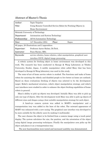
<strong>Abstract</strong> <strong>of</strong> Master’s <strong>Thesis</strong>Author: Tapio TaipalusTitle:Using Remote Controlled Service Robot for Fetching Objects inHome EnvironmentHelsinki University <strong>of</strong> TechnologyDepartment: Automation and System TechnologyPr<strong>of</strong>essorship: AS-84 Automation TechnologyDate: 14 th December 2004 Place: Espoo80 pages, 28 illustrations and 2 appendicesSupervisor: Pr<strong>of</strong>essor Aarne Halme, Dr.Tech.Instructor: Panu Harmo, MSc.Keywords: service robotics, home robotics, robot manipulation, graphical userinterface (GUI), digital image processingA robotic system for fetching object in home environment was developed in thiswork. The research has been conducted in Kosuge & Wang Laboratory at TohokuUniversity, Sendai, Japan. A mobile manipulator robot called Mary that has beendeveloped in Kosuge & Wang laboratory was used in this study.The state-<strong>of</strong>-art <strong>of</strong> home service robots is studied. The functions and tasks <strong>of</strong> homerobots for assisting the elderly and disabled people to live better at home are outlined.Based on these evaluations fetching <strong>of</strong> objects was selected to be the developmenttarget. Robot’s mechanical structure, robot’s object manipulation strategy, and robot’suser interfaces were studied in order to enhance the object fetching capabilities <strong>of</strong> homerobots in general.Mary’s ability to pick up objects was developed. Initially Mary was able to pick uponly one type <strong>of</strong> objects. After the development work Mary was able to pick up objects <strong>of</strong>different sizes and shapes using a best suitable manipulation strategy for each object.A hand-eye camera system was added to MARY’s manipulator and atransportation tray was added to the base <strong>of</strong> the robot. The outward appearance <strong>of</strong>MARY was enhanced with a new casing. The graphical user interface was developed tobe more suitable for the elderly users by making it multimodal.The user chooses the object to be fetched from a camera image using a touch paneldisplay. The system calculates the size, the position, and the orientation <strong>of</strong> the objectusing digital image processing techniques. Finally the manipulator arm picks up theobject and places it on a transportation tray.The new functionalities were tested and increased usability was demonstrated.
Diplomityön tiivistelmäTekijä: Tapio TaipalusTyön nimi: Kappaleiden nouto palvelurobotilla kotiympäristössä kauko-ohjaustakäyttäenTeknillinen korkeakouluOsasto: Automaatio- ja systeemitekniikkaPr<strong>of</strong>essuuri: AS-84 AutomaatiotekniikkaPäivämäärä: 14.12.2004 Paikka: Espoo80 sivua, 28 kuvaa ja 2 liitettäValvoja: pr<strong>of</strong>essori Aarne HalmeOhjaaja: diplomi-insinööri Panu HarmoHakusanat: palvelurobtiikka, kotirobotiikka, manipulointi strategia, graafinenkäyttöliittymä (GUI), digitaalinen kuvankäsittelyTässä työssä kehitettiin robottijärjestelmää, jonka avulla voidaan noutaa jakuljettaa tavaroita kotiympäristössä. Tutkimus tehtiin Kosuge & Wang LaboratoriossaTohokun yliopistossa Sendaissa Japanissa. Työssä käytettiin Kosuge & WangLaboratoriossa kehitettyä mobiilimanipulaattori tyyppistä MARY (Mobile AssistiveRobot for You) –robottia.Aluksi työssä selvitettiin koti- ja palvelurobotiikan tilaa ja ideoitiin toimintoja sekätehtäviä, joilla robotti voisi tukea vanhusten tai vammaisten asumista kotona.Selvityksen perustella valittiin kehityskohteeksi pienten esineiden noutaminen.Robotin rakennetta, robotin käyttämää manipulointistrategiaa ja robotinkäyttöliittymää tarkasteltiin kappaleiden noutamistehtävän kannalta.Aluksi MARY kykeni poimimaan ja noutamaan yhden tietynlaisen kappaleenkerrallaan. Järjestelmäkehityksen jälkeen robotti kykenee käsittelemään lukuisiaerikokoisia kappaleita käyttäen kullekin kappaleelle parhaiten sopivaamanipulointistrategiaa.MARY:n manipulaattoriin lisättiin kamera. Robotin runkoon rakennettiin tarjotintavaroiden kuljettamista varten. Robotin kotelointia ja ulkonäköä paranneltiin.Robotin graafista käyttöliittymää kehitettiin multimodaaliseksi ja paremminvanhuksille soveltuvaksi.Käyttäjä valitsee robottikameran kuvasta kuljetettavan kappaleen käyttäenkosketusnäyttöä. Robotti poimii kappaleen tarjottimelle, mitattuaan ensin sen koon,paikan sekä orientaation digitaalisesti kameran kuvaa käsittelemällä. Uudettoiminnallisuudet testattiin ja niiden todettiin parantavan MARY:n käytettävyyttä.2
AcknowledgementsI want to thank Pr<strong>of</strong>essor Kazuhiro Kosuge for the possibility to do this work in hislaboratory at Tohoku University, in Sendai, in Japan. I also want to thank Pr<strong>of</strong>essorAarne Halme from the Automation Technology Laboratory at Helsinki University <strong>of</strong>Technology for his help in organizing my trip to Japan. I am grateful to Panu Harmo forall the help and the advice that made this research possible, not forgetting all the staffinvolved in Terve Taas (Hello Helper) and Automaatio Avuksi (Assistive Automation)projects.I’m grateful to the Sasakawa Association for the financial support and HidenoriYabushita and Seiko Segawa from Kosuge & Wang Lab. for the help in practical matters.I greatly appreciate the help <strong>of</strong> Eriko Shibazaki and other staff at the TohokuUniversity’s International Office as well as Anneli Sinkkonen and the other staff at theHelsinki University <strong>of</strong> Technology’s International Office.Finally thanks to my family and the staff <strong>of</strong> both the laboratories for the social supportalong the way.Espoo, 14 th December 2004Tapio Taipalus3
Contents1 Introduction ..........................................................................................................91.1 Home robots ..........................................................................................................91.2 What is a robot....................................................................................................101.3 Motivation and problem statement....................................................................122 Service robotics................................................................................................... 142.1 Overview <strong>of</strong> service robotic research..................................................................142.2 Challenges in service robotics ............................................................................142.2.1 Environment ................................................................................................142.2.2 Technology....................................................................................................152.2.3 Functionality................................................................................................152.3 Required functionality <strong>of</strong> home robot.................................................................162.4 Special Requirements for assistive home robots ...............................................183 Structure <strong>of</strong> home robot...................................................................................... 203.1 Manipulation robots and information robots.....................................................203.2 MARY (Mobile Assistant Robot for You) ............................................................223.2.1 Hardware .....................................................................................................233.2.2 S<strong>of</strong>tware .......................................................................................................283.2.3 Contributions to MARY ...............................................................................304 Manipulation strategy........................................................................................ 344.1 Background .........................................................................................................344.2 Adaptive strategy................................................................................................354.2.1 Approach to object........................................................................................354.2.2 Strategies for manipulation ........................................................................375 User interface (UI).............................................................................................. 484
5.1 Varying user skills, needs and control methods............................................485.2 Implementation <strong>of</strong> UI for local remote control................................................515.2.1 Implementation options...............................................................................515.2.2 Audio ............................................................................................................545.2.3 Video .............................................................................................................576 Experiment ......................................................................................................... 627 Results ................................................................................................................ 647.1 Object extraction.................................................................................................647.2 Manipulation.......................................................................................................657.3 UI.........................................................................................................................657.4 Overall system performance...............................................................................668 Conclusions and future work ............................................................................. 679 Bibliography ....................................................................................................... 70Appendix AAppendix BSchematic drawing <strong>of</strong> electronics interface circuit designCD-ROM, source codes <strong>of</strong> the programs5
List <strong>of</strong> FiguresFigure 1.Figure 2 .Figure 3Figure 4Figure 5Figure 6Figure 7Figure 8Figure 9Figure 10Figure 11Figure 12Figure 13Figure 14Figure 15Figure 16Fictional robots, from left to right an from top to bottom, Robby in“Forbidden Planet”(1956), David and others, Bender, R2-D2 withC3PO and SonnyCommerical home robots, Aibo and AutomowerDesign examples <strong>of</strong> information robotsMARY (Mobile Assistant Robot for You), home robot prototypeMARY with some main parts pointed outA mecanum wheel, invented in Sweden 1970’s by Bengt Ilon, anengineer with the Swedish company Mecanum ABManipulator arm PA-10 by Mitsubishi Heavy IndustriesSystem scheme <strong>of</strong> main parts in MARYLaser range finder and body force sensor in old hardwareconfigurationMARY’s s<strong>of</strong>tware structureTray in MARY, arm in relaxed poseGripper with sensors and hand-eye cameraManipulation strategies, grasping side ways from the shelve on left,pushing large object on middle, grasping upwards from table on rightFree space measurement on tray, original picture on left, colorextracted in middle, filtered, cropped and measured on rightResult <strong>of</strong> window matching based on correlation, original image fromright camera on top and selected search window in right lower pictureand search result from left camera picture in left lower pictureMeasurement <strong>of</strong> object dimension from different distances and gripperfitting, first color extraction, then erosion/dilation processing andmeasurements. Pictures on right side are taken from 10 cm higherthan pictures on left.6
Figure 17Figure 18Figure 19Figure 20Figure 21Figure 22Figure 23Figure 24Figure 25Figure 26Figure 27Figure 28Triangulation <strong>of</strong> object’s distance or height <strong>of</strong> camera from objectGripper fitting around measured object from COGMeasurement process in imageObject delivery with arm and tray, relaxed pose on the leftExamples <strong>of</strong> GUIs for robot [ER1, Nomad], notice amount <strong>of</strong>information and way <strong>of</strong> presentationPrevious GUI <strong>of</strong> MARYIndicative button for speech-recognition, inactive and activeIndicative button for speec-synthesis, inactive and activeDeveloped GUI, speech-synthesis active and speech-recognitioninactiveNavigation GUI <strong>of</strong> MARY, from the upper image desired place can bedefined and from the lower image desired path can be definedFlow chart <strong>of</strong> scrollable selection on the left and tree like hierarchy onthe rightExperiment setup, evaluation <strong>of</strong> manipulation strategy7
AcronymsCOGCPUDOFGUIIEEEIPIRLANLEDMARYOSRGBRTUIUSBVISCAWLANWYTIWYGCenter Of GravityCentral Processing UnitDecrees Of FreedomGraphical User InterfaceInstitute <strong>of</strong> Electrical and Electronics EngineersInternet ProtocolInfra RedLocal Area NetworkLight Emitting DiodeMobile Assistant Robot for YouOperating SystemRed Green BlueReal TimeUser InterfaceUniversal Serial BusVIdeo System Control ArchitectureWireless Local Area NetworkWhat You Touch Is What You Get8
1 Introduction1.1 Home robotsSeveral universities and companies are developing robots for home use. The modernworld has long been eagerly awaiting the arrival <strong>of</strong> robots into our everyday lives. Mostpeople think that robots will naturally merge into our lives and become anindispensable part <strong>of</strong> our everyday routines [1]. This public opinion is clearly reflectedin movies which focus on the future: “Modern Times”(1936), “Star Wars”(1977),“Alien”(1979), “Bladerunner”(1982), “Matrix”(1999), “Futurama”(1999), “AI”(2001) and“I, Robot”(2004) [2] (Fig. 1). In turn such movies have also had dramatic impacts onforming the general public’s opinion about robots.Fig. 1. Fictional robots, from left to right an from top to bottom, Robby in“Forbidden Planet”(1956), David and others, Bender, R2-D2 withC3PO and Sonny9
On the other hand, these movies also portray an image that the presence <strong>of</strong> robots ineveryday life is just fantasy. This creates a general opinion that robots, or morespecifically service robots, are a concept far from reality today. However, during thelast 5 years companies have already been introducing real robots to consumer marketsone after another [3, 4, 5, 6] (Fig. 2).Fig. 2. Commerical home robots, Aibo and Automower [3, 6]At present these robots are only capable <strong>of</strong> performing simple tasks. But the fact thatpeople are buying them for their personal use at home is a pro<strong>of</strong> that the home robotmarket is real [7]. Can one compare first mobile phones to multi-functions <strong>of</strong> today’scommunication gadgets?1.2 What is a robotThis brings us to the definition <strong>of</strong> a robot. Some think that a perfect robot is a perfectcopy <strong>of</strong> a human being with at least the same capabilities. The perfect robot could alsobe descried as a machine which perfectly fulfills tasks assigned to it. Generally speakingrobots are considered to be part <strong>of</strong> automation. And by definition automation relieveshumans from tedious, monotonic, simple, heavy, and dangerous tasks. Also in somecases robots are used to replace manpower. But they can perform better than humans inmany tasks achieving more consistent and more precise results in a continuous workprocess. More specifically, robots in this thesis refer to physical entities, capable <strong>of</strong>changing their position or position <strong>of</strong> other physical entities with internally generatedcontrol signals to actuators. Generation <strong>of</strong> controls can be based on internally measured10
states or externally fed states <strong>of</strong> a robot. For example, automatically stop a mobile robotbefore it bumps to the wall using laser range finder measurement or drive the robot forfive meters.Control basically distinguishes a robot from an expensive piece <strong>of</strong> metal and plastic.Control can be implemented in many different ways. The simplest way is just to controlthe power <strong>of</strong> each motor in a robotic device. This scheme does not really fit into ourspecification <strong>of</strong> a robot because the control signals are not internally generated. Thenext scheme is to give a target state for the robot arm and then control its motors tomeet the desired state. This is rather a difficult and slow process for operating a robot,especially for a not very technically oriented person. This thesis focuses on moreautonomous robots. For example, a specific task is assigned to the robot and the robotthen finds out the desired endpoint coordinates by itself based on the assigned task.Although robots could be used for many tasks today, they are not implemented in everypossible case mainly because <strong>of</strong> the high purchasing cost and the expertise needed toimplement the robots in a desired process [7]. One hurdle more is our dynamic world.Processes, where robots are used, have to be consistent and long lasting enough so thatthe financial turnover time (ROI, Return Of Investment) can be achieved before changesand new costs.Traditionally a robot has to be programmed very specifically in order to be able toperform the desired tasks. Even small exceptions in robot’s environment or desired taskcould call for reprogramming <strong>of</strong> the robot by the operator. Robots should be able to adaptbetter to the changing environment. In order to make robots capable <strong>of</strong> adjusting tominor changes a much more complex program and program architecture with moresensory information is required.From the hardware point <strong>of</strong> view problems <strong>of</strong>ten arise in mechanical and actuatordesign. In order to have good accuracy in in rapid movements, the structure has to bestiff enough not to oscillate or bend. This usually makes the robot structure quite heavy.The more complex the movements are the more motors need to be implemented. As aresult the robot becomes even heavier. To be able to move the robot as fast as possiblestrong forces are required which again leads to bigger motors and consequently aheavier structure. Robot should also be able to manipulate some payload, notmentioning high precision gears, position sensors or power sources, which when addedtogether makes robots clumsy and expensive.Robotic research has tried for decades to overcome the problems described above.Several journals, conferences and university laboratories have been generated to work11
explained in experiment chapter. Finally results and future work are discussed in thelast chapter.Many closely related robotic issues are not included to narrow the scope <strong>of</strong> the study.These other issues are intensively studied elsewhere. Some examples <strong>of</strong> these issues arepath planning, localization, safety and energy sources [16, 17, 18, 19].To sum up, the purpose <strong>of</strong> this work is to find answers to the following question: “Howcan a service robot be made to fetch objects from open surfaces, such as table tops andshelves, in home environment?”13
2 Service robotics2.1 Overview <strong>of</strong> service robotic researchService robot is a robot that can serve us by doing some tasks for us, humans. Theseservice robots can be found, for example, in mines, storage rooms, <strong>of</strong>fices or homes.Sometimes “field robot” is used for service robot in outdoor environment. Variation <strong>of</strong>tasks that robots could do for us is wide. Unfortunately number and variety <strong>of</strong> tasksthat one robot really can do today, is still quite limited. This is because development <strong>of</strong>home and service robots is still a young and complex research area involved withachievements from numerous sciences, traditionally separated in university world. Thisleads to biased research projects and so not a one robot combining all advances <strong>of</strong>research field exists. Typical for service robotics research projects is that they focus onone very specific robotic detail and thus projects are unable to construct functionalsystem that really works how non technical user expects it to work. Descriptive is thatThe Technical Committee for Service Robots <strong>of</strong> the IEEE Robotics and AutomationSociety was founded only nine years ago 1995[20]. Society tries to find common goals fordispersed research and push knowledge forward. Another hurdle is that research builton the results <strong>of</strong> previous research is very difficult. This is because previous research isusually based on very specific hardware, s<strong>of</strong>tware and environment, which is difficultand expensive to duplicate.2.2 Challenges in service robotics2.2.1 EnvironmentRobots have been used in industrial production for long time. Service robots have beenhandling goods in large scale storages for some time. These robots are working inisolated environments Standardized safety regulations can be fulfilled easily, sincehumans are not allowed into the same space [18]. Humans in robot’s working area donot only create a safety risk, but they change the environment that the robot has toobserve. In order for the robots to serve us in homes or <strong>of</strong>fices, robots have to overcomethese problems. Solution used in today’s home robots [3, 5, 21] is to keep robot small,light and somewhat robust to withstand collisions and minimizing kinetic energy orimpulse to and from the environment.Another issue with environment is how to model or describe the environment.14
Industrial robots have environment build for them: clear area where they can move andwell defined contact points for manipulation. This kind <strong>of</strong> environment is easy to modelfor robotic use. In <strong>of</strong>fice or home modeling <strong>of</strong> environment is far more complex,especially if model has to contain information for different kind <strong>of</strong> tasks like where is adoor, where is a door handle, in witch way door opens and how door handle should bemanipulated or where is a trash bin, from witch direction trash bin should beapproached and how full it is. Home robots, on the market today, assume environmentto be more or less static and if modeled, it is basically simplified to a two dimensionalmap containing free area and occupied area.2.2.2 TechnologyEnvironment is not the only problem for service robots. As mentioned before,mechanical structure <strong>of</strong> a robot in it self is challenging, especially when different kinds<strong>of</strong> tasks are required. Same manipulator’s endeffecter is supposed to grip a newspaper,a plate <strong>of</strong> food or clothes, twist a screwdriver or clean [22, 23]. Then if we want to userobot in a different places, mobile robot should maneuver its way over obstacles startingfrom electric cables, carpet edges and door steps. On top <strong>of</strong> these mechanical problemsrobot has to have numerous sensors, communication interfaces and computing ability.All these parts together are creating robots functionality and requirement for energy. Tobe any way feasible to use, home or <strong>of</strong>fice robot should have operational time <strong>of</strong> severalhours and autonomous refill <strong>of</strong> energy source. In this stage it should be clear thatconstruction <strong>of</strong> home robot is not simple task and thus, with home robot’s clear need, ithas challenged and fascinated researchers for years.2.2.3 FunctionalityAs mentioned, today’s service robots are limited in the functionality and are <strong>of</strong>tendesigned to fulfill just one task, like fetching a book, opening and reading it with camera[24, 25], vacuum clean floor[4], cut grass[6] or support in walking[26]. Some attempts tomake multifunctional home robots are German Care-O-Bot [27] and Korean DO-U-MI[28]. They are getting closer to a truly useful robot, but then are still quite far fromcommercializing.From commercial or industrial research and development the strong attempt to buildhumanoid robots are likely to solve mechanical problems. Humanoid robot could provideflexible platform for home service task development in s<strong>of</strong>tware level. And when we areable to fulfill several tasks, we come to more difficult question: “What home robot should15
do?” This is difficult because there is no one and correct answer. Desired tasks are basedon individual needs. This work is focused on service and especially home robots forelderly or disabled users. From that point <strong>of</strong> view we can find some tasks that arecommonly needed.2.3 Required functionality <strong>of</strong> home robotTo find these tasks that robots should and could do interviews are done with elderlypeople, pr<strong>of</strong>essional elderly care workers and family members <strong>of</strong> elderly people. Somestudy about service robots and these interviews and discussions have been done duringTerveTaas-project[29], [30] and Automaatio Avuksi-project[31](2000- ). Study alsoincludes excursions to different elderly care institutions in Finland and in Japan. Somestatistics <strong>of</strong> conducted care work could be found from [32, 33, 34]. The needed care workis studied from a case study about the home care for elderly [35], from study aboutphysical care environment [36] and from study about development <strong>of</strong> ADL (Activities <strong>of</strong>Daily Living) [37]. Also [14] gave a good insight to the topic. Based on informationmentioned above can tasks, that are needed and could be done or supported by robots,be found. Results are presented in Table 1.Table 1. Robotics in care work <strong>of</strong> elderly and disabledProblem ordifficultyRobotic technologyor supportavailable todayRobotic technology orsupport under researchExamples <strong>of</strong> knownsolutionsLonelinessEntertainmentrobot [3]Emotion robot[38],information homerobot[39, 40], intelligenthomeHome nursing, daycenters, TV, enhancedcommunication: Internet,email, mobile phonePreparingfoodRoboticmanipulator [41]Intelligent homeFood delivery, homenursing, ready made food,food automatEating Feeding robots [42] Home nursing, easy to eatfoods, special design forfork, spoon, knife or chopsticksMedicinedispensingcontrolIntelligentmedicinedispensersIntelligent home,Home nursing, refilledmedicine containersCleaning Floor cleaning [4],[5]Window cleaning robotCleaner, home nursing,vacuum cleaner,motorized window cleaner16
Problem ordifficultyRobotic technologyor supportavailable todayRobotic technology orsupport under researchExamples <strong>of</strong> knownsolutionsShoppingInternet shopswith deliveryShopping robot,Intelligent home aware<strong>of</strong> lack <strong>of</strong> productsHome nursing, deliveryservices, catalog shoppingPersonalhygieneBathing robotMore easily accessibletoilets, functional toiletseats, home nursing,toiletry devices for bed,moveable toilet seatPassivityEntertainmentrobot [3]Home robot, EmotionrobotDay centers, therapy, clubactivitiesCommunication, (especiallywith mobilephone oremail)Information home robot,intelligent homeEasy to use phones,simpler email programsWalking ormovingElectricwheelchairs,power assistedbikes, power beds,body liftersRobotic walkers, exoskeletonrobots,automated electric wheelchairsWalking sticks,wheelchairs, walkers andrehabilitation trainingMemorylosses,dementiaElectrical diariesInformation home robot,intelligent homeReminder devices, noticeboards, relatives andnurses, diariesReduced finemotoric skills,shakinghandsRoboticmanipulators withspecial UIAutomated roboticmanipulatorHome nursing, easy to useobjects: mugs, taps, doorhandles …ReducedvisionText to speechprograms,speech-recognitionprogramsText to speech programsand speech-recognitionprograms used withhomerobotsEye classes, voiceindicators in devices,indication with texture orposition (Braille writing,grooves, switches …)Motion <strong>of</strong> thecompletely orpartlyparalyticlimbsOne DOFrehabilitationdevicesMultiple DOFrehabilitation devices orrobotsRehabilitation nursing,self powered exercisingmachinesReducedhearingSpeech-recognitionprogramsSpeech-recognitionrobots,Hearing devises (soundamplifiers), paper andpen, written informationHeart attack,epileptic fit,etc.TeleoperatedcamerasIntelligent home, homerobotEmergency buttons, homenursingThis table is not complete presentation, since it would require more intensive study andstrict definitions and classifications. Table 1 only tries to give picture <strong>of</strong> research field in17
organized order. From the above information can be concluded that present home robotscan be used for communication, handling <strong>of</strong> objects, environment and appliance control,and physical support for walking and standing up and sitting down. Service robots willnot be the ultimate answer for all problems, but they can help people live moreindependently and longer at home. Living longer at home is also considered moredesirable for the elderly people and for society around them, not needing to mentionsaved costs <strong>of</strong> care work. Now we just need a functional home robot, and that is whatresearchers all over the world are developing.2.4 Special Requirements for assistive homerobotsFunctionality and performance are important aspects <strong>of</strong> home robots. Still they do notmake a good home robot, especially for elderly. Other main issues are cost, usability,reliability and acceptance.Costs <strong>of</strong> robots are high mostly due to small production numbers. A simple manipulatorarm for wheelchair costs tens <strong>of</strong> thousands euros [43]. So it is clear that the user is notable to purchase it alone in most <strong>of</strong> the cases. Also it is difficult to market veryexpensive product to new markets and without long time references. To get the pricesdown mass production and large sales numbers are required. This means greatinvestment with considerable high risk. On the other hand there is demand andmarkets are big enough, approximately 15-35% <strong>of</strong> population in western countries(when counting all people in need <strong>of</strong> some sort <strong>of</strong> assistance at home). Still there is onlyvery few small companies like [41,42] on this market sector actually selling products onconsumer level. For entertainment purposes there are few companies selling homerobots starting from 1980’s [43]. I believe that these promises and high risks are reasonswhy many large companies like Mitsubishi [44], Sony [21], Fujitsu [40], Kawada [45]are developing products but not producing and marketing them (not forgetting the factthat they can’t deliver good enough product yet). They wait someone to try and open themarkets.If a robot is not easy to use it will not be used. And if robot is not used, people are notwilling to pay for it. Tasks that robot does, should be truly useful and done reliable. Forcomfortable use robot should be as service free as possible. Misuse, malfunctions orother exceptions should not stop the robot. It should recover especially from bugs in thes<strong>of</strong>tware level and other problems that can not be seen from outside <strong>of</strong> the robot.18
All these issues, cost, usability and reliability, effect to acceptance <strong>of</strong> robot, but there isother things involved like social status and change resistance. Everybody knows howsome children want to wear glasses to look older and some older people don’t want wearthem to look younger. The same effect is with all assistive devices, it is hard to admitthat one is getting old and needs some help. The user could just feel in negative way,that he is somehow in different group than people without home robot. User can feel therobot as a threat or frightening and especially among older people just changeresistance and fear <strong>of</strong> technology is stronger. Finally the user is not the only one toaccept robot. Also relatives, care workers and financing people (county and statepoliticians) have to accept home robot.19
3 Structure <strong>of</strong> home robot3.1 Manipulation robots and informationrobotsHome robots can be divided in to two groups: able to and unable to manipulate, in otherwords manipulation robots and information robots. Great difference between these twois size. Imagine that a robot needs to reach shelve at 220 cm and then place somethingon the floor. The manipulator arm have to be at least 110cm long as stretched out at110cm height. And when the arm have to be able to compensate small misalignmentsand manipulate objects, even larger dimensions are required. This makes manipulationrobots big. This means also that physical dimensions and power output could be bigenough to give physical support to humans like DO-U-MI [28] and Care-O-Bot [46]. Butsize has limit, many authors claim that robot should be smaller than user like Asimo[47] or Wakamaru [44]. This gives psychological effect that user rules robot andphysically smaller impulses in case <strong>of</strong> collision [18]. Main reason for required size isthat our environment, home or <strong>of</strong>fice, is designed for people. Counter tops, handles,shelves, doors, etc are all designed for the human hand hanging from our shouldersaround one and half meters from floor level. Also signs, desks, windows, lights, etc aredesigned for pair <strong>of</strong> eyes, situated slightly higher than where the arm is hanging. Thusa robot <strong>of</strong> human size and functionality is advantageous when operating in environmentfor humans.Another approach is to design and build houses for robots or both robots and humans.Such a co-existence is proposed and will be tested in Wabot-house project [48].Specialized building strategies for human-robot co-existence would increase buildingcosts. Existing buildings will be used for decades and modifications to those would beeven more expensive. It is more feasible to adapt robots to human environment thanbuild completely new environments. However, I think that in the future houseconstruction will have slight changes when the home robots become more common, likeconstruction <strong>of</strong> the broadband connections to new buildings nowadays.One approach would be co-operation <strong>of</strong> several specialized robots [49]: one robotworking on the table top, one robot transporting objects from the table level to the floorlevel and one robot transporting objects on the floor level. Also the robot size can bedecreased when comparing to previous approaches. This is maybe the most realisticapproach when using today’s technology, but clear drawbacks are costs caused by20
multiple platforms (for ex. batteries, communication interfaces, processors) and errorprone large system size with integration problems. Integration <strong>of</strong> robot to externalsystems is an open question without valid global standards. Standardization is slowsince requirements for system are conflicting, like wide bandwidth, long distance incommunication or low cost and low power consumption in system. This same problemexists in home networks [30]. Unfortunately many home robot research groups considerinterfacing home robot to home automation (intelligent home) or home network trivial.Of course one can make a connection to, for example X10 home automation network, butthere is many other home automation networks.Somehow information about other devices in home network should be programmed andthat can’t be done by elderly users. Still also I think that networking <strong>of</strong> home appliancesand home robots is essential task in order to increase autonomous functionality <strong>of</strong> arobot.If the robot does not have to manipulate anything, design <strong>of</strong> it is freer (Fig. 3). Theserobots are smaller than manipulation robots and thus more acceptable by users in homeenvironment.Fig. 3.Design examples <strong>of</strong> information robotsInformation robot is built on a mobile platform. Structure <strong>of</strong> the platform is <strong>of</strong>ten roundand with two driving wheels (two-wheel differential drive [50]) on sides so robot canturn on spot even in narrow places. This structure has simple dynamic model and is21
easy to build while moving any direction from any point. One drawback <strong>of</strong> this design isa bad maneuverability in rough terrain, but in home and <strong>of</strong>fice environment doorstepsand cables tend to be the biggest obstacles to cross. Stairs are impassable obstacle formost <strong>of</strong> the designs. Even for the bigger manipulation robots. So this has been selectedfor platform structure in many information robots over a car like structure with steeredwheels and the other wheel configurations.The main function <strong>of</strong> information robots is simply to gather and provide information invarious forms. The most common sensors are camera, microphone, ultrasonic orinfrared (IR) proximity sensor, buttons and bumpers. For information output mostcommon devices are display, signal lights, speakers and “body” language. Body languageis for example rubbing a feet <strong>of</strong> person by driving robot against it, in order to getattention. Information robot is <strong>of</strong>ten connected to internet and/or phone line. Soinformation can be sent and received from distant locations.Other function is to transfer or “amplify” information. This can create an access toinformation channels like email or help to get otherwise inaccessible information. Ainformation robot can remind about doctor’s appointment for a demented or informabout knock on the door for deaf. To increase usefulness <strong>of</strong> the information robot,sensors for smoke, carbon dioxide, light, temperature and movement can be used.Because <strong>of</strong> the great amount <strong>of</strong> available information, research challenges are more inhandling <strong>of</strong> the information than in mechatronical side. In the manipulation robotssituation is different or even opposite.3.2 MARY (Mobile Assistant Robot for You)Most <strong>of</strong> the mobile manipulator robot research is focused on tasks that are simple todescribe and to do with mobile manipulator [46, 51, 52, 53]. Mobile manipulatorcontains mobile base, usually wheeled, and manipulator arm <strong>of</strong>ten equipped withgripper. Many research groups utilize existing mobile platforms and manipulator armsto save hardware design efforts. This approach enables researchers to design and testreal tasks in short time, but restrict design to the readily available hardware. Otherdesign method is to start from the user requirements and desires. This requires <strong>of</strong>tenmore resources that research groups can provide. Practical work in this thesis isconducted with a mobile manipulator, which is a prototype home robot made from acommercial mobile platform and an arm. The robot is called MARY.22
3.2.1 HardwareFig. 4.MARY (Mobile Assistant Robot for You), home robot prototypeMARY is constructed in Kosuge & Wang Laboratory, Tohoku University, Japan. MARYis a prototype home robot for research purposes (Fig. 4). A more specific description <strong>of</strong>the construction <strong>of</strong> robot can be found in the work by Shin Aizawa [54]. Main parts <strong>of</strong>MARY (Fig. 5) are a mobile base, a manipulation arm, and three computers from whichtwo are onboard the robot23
OmnidirectionalcameraManipulator armStereo cameraHand-eye cameraComputer 2 and 3GripperBatteriesTrayMobile baseMecanum wheelsFig. 5.MARY with some main parts pointed outare presented in the Figure 5. Mobile base is modified omnidirectional electricwheelchair with mecanum wheels. Wheel is also called to omnidirectional wheel,Swedish wheel, Stanford wheel and multi DOF wheel. Wheel is constructed from rollerson wheel rim with free rolling axis not perpendicular to wheel axis (Fig. 6).24
Fig. 6. A mecanum wheel, invented in Sweden 1970’s by Bengt Ilon, anengineer with the Swedish company Mecanum ABWhen utilizing the mecanum wheels [55], base can move to any direction whilemaintaining its orientation. Drawback is that maneuverability <strong>of</strong> the mobile base inrough terrain is quite limited.The other key part is a manipulator arm PA-10 (Fig. 7) manufactured by MitsubishiHeavy Industries ltd [56]. The arm is attached up-wards on the top <strong>of</strong> platform to height<strong>of</strong> 0.80m.25
Fig. 7.Manipulator arm PA-10 by Mitsubishi Heavy IndustriesThe PA-10 has 7 decrees <strong>of</strong> freedom (DOF) and nominal payload <strong>of</strong> 10kg. Arm itselfweighs 40kg, not including the control electronics, which are in a separate control box.The manipulator is equipped with a force/moment sensor (“IFS-90M31A 50-I 50” byNitta) and a gripper (“RH707” by Takano Bearing Co., Ltd.).System <strong>of</strong> main parts is presented in Figure 8. Computer 1, running Windows XP OS(Operating System), is separate from the robot. A program for the computer 1 isdesigned for touch screen, but there are no restrictions for program to work with otherpointing devices like a mouse. One computer, comp. 2, on-board is running event drivenWindows 2000 OS and the other computer on-board, comp. 3, is running QNX RT (RealTime) OS. The computer 3 does lower level controls like control <strong>of</strong> manipulator arm andwheels or reads force sensor inputs. The computer 2 does higher level controls. It alsoprocesses images from several cameras mainly using IP-5000 image processing board.The computer 1 works as a GUI (Graphical User Interface) for robot utilizingspeech-recognition and synthesis. GUI is presented more detailed in User Interfacechapter. On-board computers are connected via Ethernet LAN (Local Area Network)and the robot is connected to same network with computer 1 via wireless local areanetwork (WLAN) transceiver (“Wireless LAN AP-11mini” by Corega).26
Ethernetcomp. 1UI (Win-XP)GUIWLANcomp. 2Win-2000 IP-5000AP-11minicomp. 3QNXLANARCNET boardCounter boardDA-BoardVISCA (serial port)Comp. videoUSBParallel portARCNETbinaryvoltageStereo cameraPanorama cameraHand-eye cameraGripperInterface boardTrayControl box ArmMobile baseFig. 8.System scheme <strong>of</strong> main parts in MARYThe commands from the GUI program are received by task process control program incomputer 2. The process control program defines needed sub tasks and based on thosegives commands to RT control program in computer 3, which calculates the neededpower outputs and sends them to control box <strong>of</strong> the arm via ARCNET. Voltage controlsto the wheel motors’ amplifiers via digital to analog (DA) converter board (“DA12 6LC”by Contec). Wheels are equipped with encoders, which are red by a counter board oncomputer 3 to calculate wheel movements. Arm-joints have encoders. The joints’positions are calculated in the control box. The position data is sent back to thecomputer 3 via ARCNET.Other functional subsystem in the robot is a vision system. The vision system includesdual black and white cameras with pan-tilt functionality (“EVI-G20” by Sony) formingstereo vision camera unit, black and white camera (“EVI-370” by Sony) withominidirectional mirror, and color camera (“QuickCam Express” by Logitech) next tomanipulator arm’s endeffecter. The last camera is forming hand-eye system. The stereocamera is used for finding out the position <strong>of</strong> a selected object relative to robot. Theomnidirectional camera is used for navigation. Color camera is used for measuringobject dimensions from different angles, for gripping point selection and for gathering27
other information for manipulation.The robot is powered with onboard lead acid batteries providing approximately twohours <strong>of</strong> intensive operation time. MARY also includes a tray for object delivery.Before my work some testing has been done with a body force sensor and a laser rangefinder, but they are not utilized much in this work. The body force sensor is constructedfrom two parallel planes and six supportive links connecting the planes (Fig. 9). Linksare used for measuring the linear force acting to them. The links are aligned in such away that combining the measured information from links, forces and torques betweenplanes can be calculated. It can work as an intelligent buffer and it is utilized as awalking support system with the same platform researched in the same laboratory [26].Some testing has been done with laser range finder (“LMS-200” by Sick) for navigationand localization. In the current hardware configuration the laser range finder with itscontrol computer is removed.body force sensor-upper plane-links-lower planelaser range finderFig. 9.Laser range finder and body force sensor in old hardwareconfiguration3.2.2 S<strong>of</strong>twareOverview <strong>of</strong> s<strong>of</strong>tware system is described in Figure 10.28
Computer 1Fetch.wpiOmniv.wpiComputer 2Fetch.mpiOmniv.mpiUser InterfaceWYTIWYG.exeClientTask flow control and image processingMary.exeServerClienttcp/ip socket connectionsComputer 3ctrlTask.ccontrol.cActuator control and sensor readingmain.cserver.cControl loopcpc.ctelnet connectionComputer XFig. 10. MARY’s s<strong>of</strong>tware structurePrograms working together to realize robot’s functionality is a complex systemincluding three different operating systems and multiple processes. Programs areprogrammed using C-language with OS specific function libraries. Also some functionlibraries for cards like IP-5000 were used.The computer 1 has a program running GUI, WYTIWYG.exe (What You Touch Is WhatYou Get), a socket client thread and loadable modules as modified DLLs (Dynamic LinkLibrary) called WPIs (WYTIWYG Plug In). Fetch.wpi is loaded when fetching task isdone and Omniv.wpi when navigation utilizing omnidirectional camera is done.The computer 2 has a main program, Mary.exe, running with a socket server and asocket client running as threads. There is also a thread for communication with thecameras via VISCA protocol (VIdeo System Control Architecture). VISCA is designed bySony to control its cameras. Mary.exe loads modules containing functions for specifictasks as a modified DLL called MPI (Mary Plug In) in a similar fashion with WPIs.29
The control program, starting from functions in main.c, in computer 3 is connected tosystem with socket server running as a thread. Another process in the computer 3 is acommand program, functions in cpc.c, for initialization and direct written commandsfrom service computer via telnet connection. One thread from control program handlesARCNET communication and for an each control cycle is a new thread started.Meaning <strong>of</strong> the WPIs and the MPIs is that they could be programmed separately andloaded when task related to WPI or MPI is needed.Complexity <strong>of</strong> the system rises from the information flow which is not implemented in astandard or otherwise well documented and specified way. Basically reason for this islack <strong>of</strong> the suitable standards and protocols in this kind <strong>of</strong> embedded system. This alsoshows clearly that there is a demand for s<strong>of</strong>tware solutions to handle complex systems.Systems with a different kind <strong>of</strong> characteristics need to cooperate and possibilities foreasier development, maintain and scalability should be created, like also recognized in[57] and [58].3.2.3 Contributions to MARY3.2.3.1 Initial functionalityWhen the work with MARY started it could fetch an object from a side view utilizingWYTIWYG GUI (Fig. 22). The arm approached the object from the side and object wasgripped from the side. The object was delivered with the gripper. When the object waspulled by user it applied a force to a force moment sensor, in the wrist <strong>of</strong> the arm (Fig.12), and triggered then the gripper to open.3.2.3.2 HardwareOn hardware side some modifications and additions are done• tray with buffer switches• driver board to interface with parallel port• hand-eye camera• optical object sensor for gripper• s<strong>of</strong>t touch senso or bumper for gripper• chassing for robot30
Fig. 11. Tray in MARY, arm in relaxed poseThe tray measures 30cm times 40cm and is made from a 3mm thick aluminum sheet(Fig. 11). The purpose <strong>of</strong> the tray is to enable the transportation <strong>of</strong> multiple objects andthe handling <strong>of</strong> objects that are too big for the gripper. It provides “closed” and fixed partto otherwise dynamic environment <strong>of</strong> the robot. Wire edges <strong>of</strong> the bumper switches canbe seen just underneath the tray and they are connected to driver board. Functionality<strong>of</strong> these is explained in more detail in Manipulation Strategy chapter.The schematic drawing <strong>of</strong> a simple driver board interfacing to the parallel port <strong>of</strong>computer 3 is presented in the Appendix A. The board has two relays driven to oppositestates with one output signal from the parallel port. 5 volt and 2.5 mA output signalfrom parallel port is amplified by operational amplifiers. Relays control approximately +or – 12 V fed directly from batteries to open and close the gripper. The board alsoamplifies signal from an optical sensor and feeds it to the parallel port among signalsfrom the bumper switches.31
The hand-eye camera (Fig. 12) is connected to USB port <strong>of</strong> the computer 2. The image iscaptured and saved from native Windows video stream. The color image is processeduntil binarized in computer’s CPU (central processing unit). The binarized image isprocessed in the image processing board. This is because image processing board canhandle only grayscale images. Used image size is 320 times 240 pixels.The optical sensor is based on an optocouple formed by an IR (infrared) LED (LightEmitting Diode) and a phototransistor. This is also included to the appendix A. Whenthe IR light produces charge transmitters in the phototransistor’s base, opens a channelto draw the output voltage level to logical low. Without the IR light, when the object isblocking, the voltage level is kept on logical high. The signal is amplified for the parallelport input.The touch sensor is formed from elastic resistive foam that keeps the switch electrodesseparated. When the foam is touched it compresses and the electrodes contact. With thisstructure we can benefit from gentle elastic characteristics <strong>of</strong> foam contact whilesensing the contact. Foam structure is also very durable against excessive touch forces.Hand-eye cameraForce moment sensorOptical sensorTouch sensorFig. 12. Gripper with sensors and hand-eye camera32
To increase safety and acceptance <strong>of</strong> the robot an elastic chasing for the robot body wasformed. Difference <strong>of</strong> the looks can be seen comparing Figures 4 and 5.3.2.3.3 S<strong>of</strong>twareThe work with this system has been mainly in the s<strong>of</strong>tware level and it is explainedmore in the following chapters. The work, not fitting under the following chapters, isexplained here. And brief explanation <strong>of</strong> conducted work to point out what was done andwhat was existing already.In the computer 1 the most significant change was implementation <strong>of</strong> aspeech-recognition and a speech-synthesis. Instructions to the user were also a newfeature and it was implemented using the speech-synthesis. Appearance <strong>of</strong> graphicaluser interface was changed and the implementations <strong>of</strong> some functionalities werechanged as explained in the user interface chapter. A one small addition was aconfiguration window where, for example, IP-number <strong>of</strong> computer 2 could be defined.The computer 2 is handling all image processing. All color image processing wasprogrammed for this work since color camera was utilized here. This means that thefunctions to fit the manipulator around the object and measurement <strong>of</strong> the free space onthe tray from hand-eye camera image were done here. The object size measurement wasprogrammed here in more reliable and accurate way. The computer 2 handles alsocontrol <strong>of</strong> the high level commands and logics for the functionalities. Logics for theintelligent manipulation strategy were programmed here.For the computer 3 several small functions were done. From which functions to controlthe arm joints with an additional angle, like “move joint-3 10 degrees more”, or tocontrol the parallel port were the most used in this work.33
4 Manipulation strategy4.1 BackgroundThe ability and the performance <strong>of</strong> the robot are <strong>of</strong>ten compared to a human or someother animal. Also design <strong>of</strong> the robots is <strong>of</strong>ten inspired by the insects, the humans orthe nature in some other ways [59, 60, 23]. This is justified since in the evolution liesthe experience <strong>of</strong> thousands <strong>of</strong> generations and it has formed a solution to many roboticproblems and the manipulation is one <strong>of</strong> them. When speaking about the home robots,these nature inspired manipulation methods would also be more feasible or natural forthe user. In the attempts to imitate the nature a one important thing is still <strong>of</strong>tenskipped with slight interest. It is difference between a muscle or the ligaments and amotor or the shafts. The movements and the mechanical solutions in the nature arebased on the muscle that actuates linearly for a limited length. On the other hand themotor produces a torque instead <strong>of</strong> a linear force and does that for an unlimited number<strong>of</strong> rotations. The motor structure is mechanically hard and static and the muscle is s<strong>of</strong>tand gives flexibility. Of course there are solutions to form the linear motion from themotor or have clutches, breaks, springs and dampers, but all <strong>of</strong> these are included in thestructure <strong>of</strong> muscle. The characteristics <strong>of</strong> muscle motion could be imitated [60, 61] butthe weight and the size are far from the muscle. Other solution is a liquid or a gas piston,which has the same limited linear motion than the muscle and some othercharacteristics <strong>of</strong> the muscle. The control and the energy source are more complex toprovide with the pistons than with the motors and especially the electric motors.Another great difference from a view point <strong>of</strong> control is that the motors are easy to equipwith an accurate position sensor and the humans can’t sense the position <strong>of</strong> the jointsdirectly. This difference does not mean that the muscle is a superior effecter but it hasthe characteristics different from the today’s effectors. The development <strong>of</strong> the evolutionis based on the characteristics <strong>of</strong> the muscle and the nerve system. This should beconsidered more carefully in the comparisons.What is superior with the humans compared to the today’s technology is the handlingand the gathering <strong>of</strong> information from the physical environment. The humans cannavigate and localize themselves. We can filter and store only the relevant informationfrom the flood coming to our retina and eardrums every second. I think that the mostsignificant ability is to recognize the objects and the surrounding environment in a3-dimensional (3D) space from the multiple glues with an amazing speed. For themanipulation not only recognition <strong>of</strong> the object is important, but the information how34
different kind <strong>of</strong> objects should be manipulated is even more important. Lifting a knifefrom the handle, lifting the classes so that the lenses won’t get scratched or lifting aclass <strong>of</strong> water without spill are learned skills. We learn new skills and improve the oldskills all the time. Not mentioning the creativity to grip the prior unknown objects orthe know objects in a new way from a right point and with a right grip by adapting theprehensile postures or the grasp taxonomies [23]. The ability <strong>of</strong> the human toapproximate and reason the information about the object’s characteristics, like weight,friction, elasticity, temperature, stiffness or mechanical strength, just by looking at itin its environment is marvelous. Try to approximate with the computer how, forexample, a pencil or a chalk bends and breaks when bent just by glancing it. The exactmodel, how humans do this, is still undiscovered. Thus only the external effects <strong>of</strong> thehuman thinking and control could be imitated in the robotics, like force control [62, 63,64, 59] or grasping point selection [23, 65].Most <strong>of</strong> the research in the object manipulation, especially in the service robotics, isconcentrated on grasping the object from an optimal place, direction and force.Unfortunately the objects are not floating in the air allowing us to approach those fromdifferent directions. The home environment is designed mainly for the manipulationfrom a case specific direction, like the kitchen table or the countertop from top, and theshelves from side and the work desk, where you sit next to the desk, from slanted. Usingthis information the motion planning and the grasp planning can be simplified. Theconcentration only on the grasping is also limiting the possible solutions. For a human,wrapping fingers around the object is only one way to manipulate. If the object is too bigfor grasping, it is slid or rolled or just both hands are used providing a gripper opening<strong>of</strong> almost two meters for an average adult. Or imagine using gravity like in handling <strong>of</strong>a big plate or furniture by supporting it from under. If the object is still too big, too smallor too many, a human can use simple tools like a rope, a tweezers or a tray. Thepossibilities <strong>of</strong> the environment can also be used, like when cleaning the table andwiping crumbs over the edge <strong>of</strong> the table to the open palm. This flexibility in the objecthandling is not just because the mechanics <strong>of</strong> the human hand, robotically stillunmatched [66], but because the even more unmatched creativity <strong>of</strong> the human mindand the humans’ effective usage <strong>of</strong> the learned skills.4.2 Adaptive strategy4.2.1 Approach to objectThe research problem was to fetch the objects in the home environment. The idea in this35
system is that the user manipulates the objects by him or her self using the robot. Sothe user specifies the wanted object by the changing needs. Otherwise the system wouldbe programmed to, for example, bring a breakfast c<strong>of</strong>fee and a morning paper in thespecific time and place every day without actual commands. MARY can be remotelynavigated to the proximity <strong>of</strong> the object as defined in [54]. In the proximity <strong>of</strong> the object,object is selected, picked and transported back to the user.The first problem in the object manipulation is to identify and localize the object. Overthe years many ways to autonomously detect the object has been presented. The robotcan have model from the environment with the locations <strong>of</strong> objects, but updating thatmodel could be tricky in the normal home environment. Some dispensers or stacks couldbe used to have fixed position for the fetched objects, like the name card holder inCare-o-bot [46]. Barcodes or other visual tags are also used, but this requires markingand or placement <strong>of</strong> every object so that the tags could be read with a laser scanner or acamera. Maybe the most promising technology would be the RFID (Radio FrequencyIDentification) tags [67] that are planned to be placed from the pavement to a sausagepackage. These tags could have a great amount <strong>of</strong> data about the objects in a machinereadable form, readable from a distance. Unfortunately the antennas for reading thetags can’t yet provide an accurate enough position information for the manipulation.Other popular options are the 3D scanning with the stereo camera or the laser rangefinder and the object recognition from a camera image. The combination <strong>of</strong> these two isused in Care-o-bot [27], but the system tries to find a taught object automatically frompredefined locations. The object recognition, when in the range <strong>of</strong> sensor, is hard to thetoday’s autonomous systems leave alone searching for the object around the house. Wewish to select an arbitrary object in arbitrary locations and it seems that the humanselecting the object from the camera image is the most effective in this task. The cameraimage is already in a human readable form and easy to comprehend by the elderly userand that is why the human selection is used in this system. This also guarantees thatthe user gets exactly what he wants and not, for example, a light soda bottle instead <strong>of</strong> aregular. The object selection is explained more carefully in the user interface chapternext.In this research assumptions are used, like the humans do, to simplify the manipulationstrategy. First the object selection is done from the camera image, which can guaranteein some level that the space between the object and the camera is free. Placing themanipulator close and lined with the camera and approaching the object location, tableor shelf, from the designed direction, like descript before, we can assume an obstaclefree path for the manipulator. This makes the defining <strong>of</strong> the path very fast compared tothe case where you measure whole environment. After measuring whole environment it36
is needed to find the obstacles with the obstacle free path and possibly a right approachdirection for the manipulator [41, 68, 69] which is a slow and an error prone process. Ofcourse this proposed method is based only on an assumption and the touch-, forcesensors and the fed current to motors are used to detect collisions. Anyhow even withthe different manipulation strategy the same collision detections are used since nosensor is 100% reliable and the home environment is dynamic. With the currenthardware <strong>of</strong> MARY even better safety could achieved with the image processing. With aknown position and a shape <strong>of</strong> manipulator in the image, the manipulator could becancelled out. The rest <strong>of</strong> the picture could be examined with motion detectionalgorithm. This would be a computationally heavy task and just a supplementary force,touch or human motion (IR) sensors could be used. Naturally to be safe to use in thehome with the elderly user, this robot should have better ways to detect the collisions.But as stated before, this is just a prototype for testing. A parallel gripper is usedbecause <strong>of</strong> many reasons. First it was already installed to the robot. Second, thecomplex gripper or hand would increase the complexity and the error probability <strong>of</strong> thesystem. Third, this kind <strong>of</strong> hand configuration is durable and cheap and so a very likelyselection for the first commercial or clinical test versions. Fourth, selection <strong>of</strong> the objectsize is easy to rule and thus usable in this experiment. And finally the effectivenessdepends more from the skill to use capabilities than from the number <strong>of</strong> possiblecapabilities, like the simple forklifts can show [70].4.2.2 Strategies for manipulationTo find the different kind <strong>of</strong> manipulation strategies the adaptability <strong>of</strong> a human wasused so that the human operator was trying to manipulate the object with used gripper(Fig. 13). Three manipulation strategies were selected: Gripping from side in uprightposition from shelves. Gripping from top around <strong>of</strong> approximated the thinnest part <strong>of</strong>object on table. Approaching object from top and sliding object with pushing it from theside on table.37
Fig. 13. Manipulation strategies, grasping side ways from the shelve on left,pushing large object on middle, grasping upwards from table on rightTo select which manipulation strategy to use a fuzzy logic could be used. Variables areposition <strong>of</strong> the robot relative to the desk or shelve and the height <strong>of</strong> the object positioncompared to standard desk height (50cm). If we can’t be sure enough the user isprompted.Before trying to get anything the robot checks how much space there is available on thetray. This is done by the image processing, color extraction explained shortly, using aknown color <strong>of</strong> the tray (Fig. 14).Fig. 14. Free space measurement on tray, original picture on left, colorextracted in middle, filtered, cropped and measured on rightThe tray is filled starting from left and in the s<strong>of</strong>tware presentation <strong>of</strong> the tray theobject occupies area for whole width <strong>of</strong> the tray. This is not the optimal use <strong>of</strong> the tray,38
ut makes the modeling simpler with an arbitrary object shapes.4.2.2.1 Object on shelfAfter the object selection its position is measured with the stereo camera using awindow matching (Fig. 15) and the trigonometry. The manipulation strategy is thenselected based on the measurement. In the window matching a specified small window(image from the right camera), smaller than the target image (image from the leftcamera), is compared in different places <strong>of</strong> the target image. The place with the greatestcorrelation is selected as a matching window.Fig. 15. Result <strong>of</strong> window matching based on correlation, original image fromright camera on top and selected search window in right lower pictureand search result from left camera picture in left lower pictureIn the case <strong>of</strong> sideways manipulation for shelves the object’s size is approximated andchecked if the gripper fits around the object in horizontal axis. The gripper is moved andopened next to the object and the object is approached directly from the side. Thegripper is moved until it is in position <strong>of</strong> the object or the wrist force sensor detects the39
contact. The gripper is closed and the object can be moved. This strategy is explained inmore detail in [54].4.2.2.2 Object on tableIn the case <strong>of</strong> object on the table, the robot and the tray are moved next to the table. It isassumed that a navigation system can take the robot roughly to the proximity <strong>of</strong> thetable and the bumper switches are used to bring the tray next to the table edge. Thetray is already fixed to the same level with the table. If the home environment containsmany table heights, the tray could be adjustable.The manipulator arm with the hand-eye camera is moved over the object. Then a newpicture is taken from a top view and the object is extracted. An assumption that thecolor and the texture <strong>of</strong> the tabletop are more or less uniformal is used for the objectextraction. The object is assumed to be around the center <strong>of</strong> image and the backgroundin the corners <strong>of</strong> image. The background color is sampled from the corners <strong>of</strong> the imageand averaged component wise; red, green and blue (RGB). The averaging is done with aspherical volume around the average color in an RGB-space. The thresholding is donethen to binarize and extract the object as seen in the first two picture pairs in the Figure16. This was done in the computer 2’s main CPU. Using another color representationlike the HSI [71] or the CIE L*a*b* can the extraction quality be increased. The systemprovides the image in the RGB format and changing that is computationally costly,especially when the results with the RGB are good enough. The binarized image isfiltered with the erosion and the dilation processes using the image processing board.The results can be seen from the second and the third image pair in the Figure 16. Thefiltered image is then checked if there are multiple objects and in such a case user isasked to define the object from a top view.There are many ways to extract the object from the image, like snakes after edgedetection [72], histogram filtering, edge detection and filtering [73], 3D extraction frommultiple images or background cancellation from an environment model and a knownposition, but selected method seemed to be computationally fastest and robust enoughfor use (Fig 16).While this image processing is running on the computer 2, the computer 3 is moving thearm 10cm higher. After object extraction the object dimension are measured in twodirections crossing the center <strong>of</strong> gravity (COG) as seen in the last image pair <strong>of</strong> Figure16.40
Fig. 16. Measurement <strong>of</strong> object dimension from different distances and gripperfitting, first color extraction, then erosion/dilation processing andmeasurements Pictures on right side are taken 10cm higher thanpictures on left.41
This was done to have an extra measurement from the position <strong>of</strong> the object. Atriangulation was used as proposed in [72] to define the distance <strong>of</strong> object from twoimages. The images were taken from two different places with a know declination(10cm) along the optical axsis (Fig. 17).x’xfhdXFig. 17. Triangulation <strong>of</strong> object’s distance or height <strong>of</strong> camera from objectHere f is focal length <strong>of</strong> the camera, h is distance to from camera to the object, d is thedisplacement between images, 10 cm in this case, x and x’ size <strong>of</strong> the object image and Xthe size <strong>of</strong> object it self. This distance h is calculated asXhx'= (1a)fX =h − dxf(1b)dh = . (1c)x1−x 'We know that x and x’ are the same object we can get h even without knowing f or X.The distance h is needed especially to scale the pixels to meters and to know, forexample, the width <strong>of</strong> gripper in pixels.The main direction for measurement is in a principle axis <strong>of</strong> inertia and the other42
direction is perpendicular to this axis. The axis is found using function library <strong>of</strong> imageprocessing board. The usage <strong>of</strong> these directions can be seen from Figures 16 and 18. Inthe Figure 16 we get two independent sets <strong>of</strong> x and x’ for equation (1).Now with known distance to object, gripper is fitted around object’s center <strong>of</strong> gravity t<strong>of</strong>ind if gripper fits and what would be central point for gripping (Fig. 18).Fig. 18. Gripper fitting around measured object from COGThe measurements are done with the Bresenham line algorithm developed in 1962 inthe IBM laboratory. The basic algorithm applies only from 0 to 45 degrees, so use <strong>of</strong> thealgorithm is divided to eight sectors.________________________________________________________________________________int loop = 0;int x, y;int dx, dy;int incx, incy;int balance;if (x2 >= *x1) //right half plane, octants 1,2,7 and 8{dx = x2 - *x1;incx = 1;}else //left half plane, octants 3,4,5 and 6{dx = *x1 - x2;incx = -1;}if (y2 >= *y1) //upper half plane (lower in image co-ordinates), octants 1,2,3 and 4{43
dy = y2 - *y1;incy = 1;}else //lower half plane, octants 5,6,7 and 8{dy = *y1 - y2;incy = -1;}x = *x1;y = *y1;if (dx >= dy) //octants 1,4,5 and 8{dy
}*x1 = x;*y1 = y;MessageBox( NULL, "Algorithm error inbitmapOpe.cpp/LineSearch().", "Error!",MB_OK|MB_ICONWARNING );CloseImg();return -1;}//check pixel valueReadPixel(x, y, &pix);if (pix == colour) break; //point foundelse{pix = (char)255;WritePixel(x,y, colour);//mark checked pixel}if (balance >= 0){x += incx;balance -= dy;}balance += dx;y += incy;}_____________________________________________________________________________________The object is searched from the image along descript axis starting from the edge <strong>of</strong>image going towards COG <strong>of</strong> the object (Fig. 19).principle axis <strong>of</strong> inertiaXMeasurement lineYCOGAobjectBFig. 19. Measurement process in image45
Now x for equation (1) is found easily from( x − x ) + ( y − y ) 2A2 B A Bx = . (2)The line search is also used in the gripper fitting (Fig. 18) with set <strong>of</strong> lines where thelines are as long as the gripper is wide. If the gripper fits, the object is gripped andmoved to the free space on the tray. In s case <strong>of</strong> too big object it is checked that if theobject fits even on the tray. If the object still fits on the tray, it is slid with a movementvector crossing COG towards the edge <strong>of</strong> the free space on tray. On the edge <strong>of</strong> the traydirection is changed directly to the tray.As mentioned before, picking the objects up from a floor level is desired task, butimpossible with current arm configuration. Still this manipulation strategy for tableapplies almost directly to the floor level picking up task.4.2.2.3 Object deliveryDelivery <strong>of</strong> the object is important and <strong>of</strong>ten a belittled part <strong>of</strong> the object manipulationin the research topics <strong>of</strong> the service robotics. Often the object is handed to the user withthe gripper after a successful grip. In this case, there is always a safety risk caused bythe moving arm. Another safety risk is an extracted arm that can dilate the robotdimensions and thus affect to navigation. When turning on the spot, the endeffecter farfrom the turning axis, it can have fast unexpected movements from the user’s point <strong>of</strong>view. This is one reason why the tray is proposed in this work as a delivery tool. Anotherissue is a so called relaxed pose where robot arm is in special position. In the relaxedpose the arm is hanging so that it looks like relaxed, at least as much as the robot handcan look relaxed (Fig. 20) .Fig. 20. Object delivery with arm and tray, relaxed pose on the leftThis makes the robot friendlier and decreases mentioned safety risks. It could be even46
more feasible if the arm could be folded inside the robot. All the robot movements arefollowing a bell shaped speed curve to make the movement <strong>of</strong> the robot arm, not onlys<strong>of</strong>t for the mechanics, but feasible for the human to see as proposed in [60].47
5 User interface (UI)5.1 Varying user skills, needs and controlmethodsThe role <strong>of</strong> the UI in the home robot could not be highlighted too much especially withthe elderly users. It defines how much, how efficiently and how pleasantly the robot isused. The role <strong>of</strong> the UI is to transfer the user’s control commands to an understandableform for the robot and to provide information from the robot in a human understandableform. The home robot UI is a tool for controlling the functions <strong>of</strong> the robot and anintelligent environment, for communication with another people and for communicationwith the robot. Communicating with the robot can have entertaining effects as well astherapeutic effects [74, 75, 38, 76]. A well designed UI can adapt to the user making theusage more efficient and pleasant [77, 53]. This could help in a general UI paradox:Usually an effective UI is a hard to learn in beginning and an easy-to-use UI tends to beineffective in extensive use. The UI should not adapt only to the skill level <strong>of</strong> the user,but it should also adapt to the user’s needs and intentions. Different cathegories <strong>of</strong>home robot users with various needs and skills are listed in Table 2.48
Table 2. User characteristics from home robots’ point <strong>of</strong> viewUser groupCharacteristicsStandard“normal” userUsed to use home electronics and open to new technology, can fullyuse own body and most <strong>of</strong> user interfaces are designed for these,overall users with all control levels, Example: Average citizenStandard elderlyuserUsed to use home electronics and afraid <strong>of</strong> new technology, can useall body functions but with reduced effect, usual problems withseeing and hearing, psychological barriers not admitting to be old,usual in-situ usersStandard“disabled” userUsed to use home electronics and open to new technology, somebody function is not working and used to compensate that withtechnology, usual in-situ usersStandard “careperson” userUsed to use home and hospital electronics but not more advancedtechnology, knowledge <strong>of</strong> patients’ or customers’ problems andsolutions for those, usual remote user <strong>of</strong> home robot with full accessto robots functionality.Standard “friendsand relatives”userUsed to use home electronics and open to new technology, willing tohelp patients or customers but don’t have all knowledge how to,usual remote user <strong>of</strong> home robot with limited access to robotsfunctionality.49
The user groups in Table 2 are exemplary. They show that there are needs for differentUI designs for different users. Another noteworthy aspect at the home robot UI is itsfour level control hierarchy:• Tool kind <strong>of</strong> control‣ UI is physical part <strong>of</strong> robot. Controlling is done there where the robot is.‣ Hardware connections without communication delay‣ Example: Manus arm [41]• Local remote control‣ UI separated from robot‣ Wireless communication directly to robot or trough a small network withoutsignificant communication delay‣ Example: Care-O-Bot [27], MARY• Long distance remote control‣ UI usually integrated to existing hardware with other main functionality,example a mobile phone.‣ Communication channel combines different technologies. Significant andvariable communication delays possible.‣ Higher level <strong>of</strong> commands and some automated functions needed‣ Example: Vacuum cleaner controlled via internet or via mobile phone [78]• Autonomous robots‣ UI is not essential part <strong>of</strong> robot‣ Predefined automated functions and independent decision making‣ No commands or commands on very general level, execute specific actions orbehaviors as reaction to some event -> teaching and commanding instead <strong>of</strong>programming and controlling or “driving”‣ Example: Robotic entertainment robot Aibo [3], smart elevator doorThis work concentrates on home robot with “standard elderly” users and with “local50
emote control” UI. The UI is designed for a single elderly user <strong>of</strong> MARY. With “localremote control” elderly users could use the robot whenever there is a need. The “toolkind <strong>of</strong> control” would be mentally burdensome for the elderly user. The long distanceremote control could be implemented easily on top <strong>of</strong> the working “local remote control”scheme. The fully autonomous robot for this task is still unreachable with the currenttechnology and knowledge.5.2 Implementation <strong>of</strong> UI for local remotecontrol5.2.1 Implementation optionsThe UI for the home robot is <strong>of</strong>ten realized with the well defined and widely knowstandard computer input and output devices like a keyboard, a mouse, a display and aspeaker including a s<strong>of</strong>tware support from the operating system [79]. Easy-to-useinterface is <strong>of</strong>ten considered to be a GUI (Graphical User Interface) over console typetext input interface (Fig. 21).51
Fig. 21. Examples <strong>of</strong> GUIs for robot [80, 81], notice amount <strong>of</strong> information andway <strong>of</strong> presentation52
From the Figure 21 we can see that GUI does not necessarily mean the easy-to-use UIespecially for elderly user. Much data is presented in numeric form without a crispfeedback or cues what the data they prefers to. The GUIs in Figure 21 utilize tabs,menus, windows, buttons and other familiar GUI elements for the computer users.Unfortunately the computer is still so new device that the senior citizens are generallyunfamiliar with them and the ailments brought with age, like shaking hands, decreasedvision and perceiving problems, makes the use more difficult. This is why also adifferent kind <strong>of</strong> input interfaces has been presented.• Hand gestures• Voice inputs• Touch screen input• Eye gaze tracking• Face and facial expression trackingHand gestures [82, 71, 83], voice inputs [84, 85, 86, 87, 53] and touch input [28, 85, 46]are the most popular Voice and touch are also used in MARY. The eye gaze and the facetracking are researched as input methods, but not yet implemented so much for realrobots [88, 89, 90, 91, 92]. Worth <strong>of</strong> mention is that, the eye gaze tracking requires <strong>of</strong>tenspecific devices mounted on the user making it awkward to use.There are many other input methods, mainly designed for seriously handicapped. Theserequire a special hardware and user training and thus are somewhat impractical for the“general use” home robot. Already commercial solutions <strong>of</strong> these methods are discussedshortly in [93].For the output the computer displays and speakers are the most used. An audio outputfrom the speakers can be a speech and beeps or other sound effects. The display canprovide information from a text and pictures to an animated face [94] or avisualization <strong>of</strong> the sensor readings instead <strong>of</strong> the plain numbers. The robot can showgestures using its actuators like by following the user with a gaze <strong>of</strong> camera or just byspinning around from happiness. There are even robots providing a facial or otherimpression with actuators designed only for that [95, 96]. The touch output is aneffective but a risky approach. It is realized only with harmlessly small robots andindirectly with force feedback control in the tele-robotic installations and the roboticwalking helpers.My work to develop the UI for MARY is based on previous easy-to-use [54] GUI (Fig.53
22).Fig. 22. Previous GUI <strong>of</strong> MARYThe goal <strong>of</strong> this development was to reduce the abstraction level <strong>of</strong> system to the user, toavoid a visual overload to the user, to make the usage more intuitive and natural. Forthis the speech input and output was implemented in order to make the usage easierwith multimodality and increase the “personality” <strong>of</strong> the robot. Some kind <strong>of</strong> personalitymakes the robot more acceptable. Also some changes, to meet mentioned goals, in theappearance <strong>of</strong> robot and in its functionality, as described in previous chapters, weremade.5.2.2 AudioBecause still unsure and delayed speech-recognition the high level commands and thestep-wise low level commands are used instead <strong>of</strong> the real time low level commands. Forexample, when driving the robot into an elevator with the real time low level command“move forward” and “stop” it would be difficult to reliably stop before the back-wall <strong>of</strong>the elevator. The emphasis <strong>of</strong> speech input is not to control the robot only with thespeech but enhance the UI with the multimodality. This is because <strong>of</strong> the limitations <strong>of</strong>54
the today’s speech-recognition. Complete and natural speech-control would need anatural language interpreter and it would be just impractical. It is much easier to pointthe object from picture with a finger than describe: “Left, more left, there, no up, back,right…”The speech-recognition is activated using the touch input or calling the robot. Theactivation is indicated with a button that also can be used to control the activation (Fig.23).Fig. 23. Indicative button for speech-recognition, inactive and activeTo make the usage more intuitive, spoken instructions are given after activation and adelay without the control actions. The activation and other actions are indicated alsowith speech. If the speaking robot is too noisy, the speech can be cut down with a voicecommand or an indicative button (Fig. 24)Fig. 24. Indicative button for speec-synthesis, inactive and active55
The problem in voice commands is the command word selection. There are many waysto express same task: ”Have a seat.”, ”Sit down, please.” or “Please” and point out emptychair. And using just a one word can be tricky because <strong>of</strong> the synonyms. This is why“correct” words are used in instructions and visual cue text under buttons. Also somesynonyms are accepted, but the increasing number <strong>of</strong> recognized words will decreasethe reliability <strong>of</strong> the recognition. This is why, for example, in the action confirmation therecognition decision is made only between “yes” and “no” to make it reliable.The speech system is realized with Micros<strong>of</strong>t Speech SDK 5.1 (S<strong>of</strong>tware DevelopmentKit) which is free to download from Micros<strong>of</strong>t’s web page with its documentation [97].This was selected among other commercial and open source solutions ViaVoice andOpen Mind Speech [98, 99] because UI was realized in Micros<strong>of</strong>t Windows environmentand so the native system would more likely work seamlessly. Also SDK 5.1, whenselected, was a quite resent release so it has most likely the latest results from thespeech-recognition research. Technically system integrates to UI application with COMinterface (Component Object Model). The system doesn’t need teaching from the useralthough if done, it can improve recognition result. The recognition is based on therecognition <strong>of</strong> phrases and syllable kind <strong>of</strong> sounds. So recognition engine does not try tocompare heard words but syllables and it is using words and phrases to decide heardsyllables from candidates using hidden Markov models. This context relation inrecognition leads to the reasonable better results than with the older methods. Thenatural changes in speech, tone, speed, pitch, intonation and etc., does not have such agreat effect and the system is partly user independent. Drawback is that the providedrecognition engine is somewhat closed system including only English, Chinese andJapanese. Modifications are hard to make, even though the system has plenty <strong>of</strong>functions for trimming and even a third party recognition engine could be implemented.Without modification the other languages are hard to realize, but a successful testingusing words from the unsupported language including only the same syllables as some<strong>of</strong> the supported languages was done. Still this workaround limits some <strong>of</strong> the intuitiveand natural words from use and the closed system prevents from finding the moreeffective workarounds.Another disadvantage with this speech-recognition system, and with all the others, isthat usually the elderly people do not articulate clearly, can have some physiologicalproblems in a sound generation and even use the “old” words or dialects that are notunderstood while having difficulties in using the “new” words for the control. In thissense it could be reasonable to use the speech-recognition system with taught words andvoices, but I think that the benefits <strong>of</strong> the used system with the independency <strong>of</strong> thenatural changes in the speech are grater than its drawbacks and I believe that the56
ecognition engines in near future or already existing engines can overcome thesedrawbacks, for example with a more suitable syllable library. In limitations <strong>of</strong> the scope<strong>of</strong> this work I did not do a wider search for other engines and their implementations tothe system.The speech-synthesis or TTS (Text-To-Speech) feature is included in SDK 5.1. Itcontains three different speech “personalities” two male voices and a one female voicenamed conveniently “Mary” which was also used in this work. A speed <strong>of</strong> the speech canbe adjusted and the speech has some intonation. Even tough the speech is wellunderstandable; it is easily recognized to a synthesized speech. In this case that isalmost a feasible feature since it indicates that the speech is created by a machine andnot by a real person. Otherwise it could be confusing for the elderly people.The reliable speech-recognition requires also a good sound quality and this requires agood microphone and a silent environment. In the most cases, including this,microphone is close to the user’s mouth in order to have a better signal to noise ratio.The speech-recognition is used simultaneously with the synthesis, so to avoid thedisturbances headphones are used.5.2.3 VideoThe developed GUI works for manipulation and driving <strong>of</strong> MARY (Fig. 25).57
Fig. 25. Developed GUI, speech-synthesis active and speech-recognitioninactiveSeparate view for the navigation was basically left as it was since the navigation itselfneeds more development (Fig. 26).58
Fig. 26.Navigation GUI <strong>of</strong> MARY, from the upper image desired place can bedefined and from the lower image desired path can be definedThe task selection was changed from scrollable window to a tree like logical structurebased on the buttons (Fig. 27). This way the user makes the selection from fewer optionsand thus the presented information and the risk for the information overload can bereduced.59
BCDEHIFGDEFGHABCIAFig. 27. Flow chart <strong>of</strong> scrollable selection on the left and tree like hierarchy onthe rightThe text cues for buttons were enhanced with icons and the left-right camera selectionbutton and the centralizing button were removed because <strong>of</strong> their small benefit to theoverall system functionality. As mentioned, the keywords for speech-recognition werepresented. The background and color theme was made more peaceful. For themanipulation task the coordinates <strong>of</strong> the object was removed as confusing informationfor the elderly users. For the manipulation only one button was used, due to changedmanipulation strategy. All these changes were motivated by the goals mentioned earlier.Many times the same command can be given with touch and voice. This kind <strong>of</strong>alternative solutions makes the UI more usable.The usage <strong>of</strong> the UI is based on the user’s inputs with touch and voice. The user canselect the object, from the video window providing a real time image from MARY, bydrawing a rectangle around the object with touch. After the selection the system tries t<strong>of</strong>ind the object. If the image processing is successful, it is visually indicated with thebutton and the user can attempt to get the object on tray with the voice or the touchcommand. The manipulation processing after that is described in the previous chapter.60
The successfulness <strong>of</strong> manipulation is then prompted to the user while the user canfollow the whole process from the video stream.61
6 ExperimentIn the experiment new manipulation strategies were tested. This means manipulatingobjects on the table. First the image processing and the manipulation strategy selectionand then the motion and the functionality <strong>of</strong> robot were evaluated. Figure 28 showsused experiment setup.Fig. 28. Experiment setup, evaluation <strong>of</strong> manipulation strategyUnfortunately the localization <strong>of</strong> robot is not developed enough, so system testing couldnot be done completely. Simulated values were used for the position <strong>of</strong> robot relative tothe furniture. The used color extraction method was tested with two different kinds <strong>of</strong>backgrounds, green paper and newspaper, and 4 different objects:• Fork• Plain CD-case• Medicine bottle• Varicolored bowl62
In the main test the different objects are placed on the table using a fixed point. Thepoint is fed as a simulated user input to the system. The measurements were done aftereach attempt from the saved images from different phases <strong>of</strong> the process and fromvariables shown to user during the test process. The testing took two days with 40attempts. A set <strong>of</strong> images in a successful attempt are presented in the Figure 16.Due to the mentioned limitations <strong>of</strong> speech-recognition, UI was realized and tested onlyin English. The system was tied to the laboratory in Sendai, Japan, so elderly naturalEnglish speakers were difficult to find. Instead <strong>of</strong> the elderly people three young adultEnglish speakers were used to evaluate speech-recognition and other functions in UI byobserving UI usage. A virtual environment was programmed to simulate MARY in theUI computer. The UI could be tested with elderly people in the natural homeenvironment. But it was found that the virtual system did not describe the real worldsystem well enough, especially without the real the robot and it was still difficult to findsuitable subjects. Also it has been noticed in another research and by my personalexperience that an analytical data gathered from the elderly people is not reliable.The overall system functionality was proven by experiments where the users got threedifferent objects with the three different manipulation strategies in the home kind <strong>of</strong>environment. The medicine bottle from shelve and the bowl <strong>of</strong> food and a banana fromthe table. Some <strong>of</strong> the experiment was recorded with video camera.The object delivery was designed to do with arm in “relaxed” pose using tray instead <strong>of</strong>handing over with arm. No experiment was done to evaluate effect <strong>of</strong> this method and itis not even necessary since benefits are so clear.63
7 Results7.1 Object extractionThe object is found and measured. An independency <strong>of</strong> extraction process from thebackground texture is good. This was recognized with the main test and also infunctionality testing with various backgrounds. Errors in the color representation in thedifferent illumination and with different cameras have a remarkable effect. The results<strong>of</strong> the main test for 10 measurements with each <strong>of</strong> the test objects (fork, medicine bottle,bowl and CD-case) using two backgrounds (green paper and news paper) are presentedin Table 3.Table 3. Results <strong>of</strong> main test for image processingObject Found* Distancecorrect (+/-5cm)*Gripper fittedto correctplace*Gripper fittingcorrect*Fork 8 4 6 5Medicine bottle 9 1 9 8Bowl 10 4 10 9CD-case 10 5 10 10*times from 10 testsFound means that measured object was found from the background. Distance wasmeasured as described in the manipulation strategy chapter. Measurement was done56cm from a table surface. The fitting place <strong>of</strong> the gripper was correct when it was donefrom a right direction to proximity <strong>of</strong> a real COG <strong>of</strong> the object. The gripper was fittingcorrectly when result <strong>of</strong> fitting was realistic and not, for example, mixed because <strong>of</strong>noise in image after filtering.From the table we can see that the stainless steel fork camouflaged well into thenewspaper. The pr<strong>of</strong>ile <strong>of</strong> the medicine bottle from top-view was quite small, and this isseen especially in the bad results <strong>of</strong> the distance measurement. With smaller objects64
there are fewer pixels presenting them and the misalignment <strong>of</strong> just a few pixels makesa remarkable difference. Generally it can be said that with this object extraction methodthe proposed distance measurement is not reliable enough to use. The edge <strong>of</strong> theextracted object is too vague for this kind <strong>of</strong> measurement. There is also a minimumdimension for the object and it is ca one centimeter from used distance. Too smallobjects would be discarded as a noise.7.2 ManipulationAdapting the manipulation strategy based on the information about the object is provento be a working concept. It makes the UI simpler and use <strong>of</strong> the endeffecter efficient forthe elderly or another non-specialist operator. Some problems were found with thecontact to the table surface when pushing the object. Sometimes a tablecloth was pulledby the arm while pushing the object. The solution was to lift the arm up a bit aftercontact to the surface, but then very low pr<strong>of</strong>ile objects like magazines, papers and disks,could not be manipulated. On the other hand it could be assumed that the elderly people,needing this much care, does not have the tablecloths to make the cleaning easier.The only problem in the usage <strong>of</strong> the tray was that the full tray with dark or lightobjects was affecting to the automatic brightness control <strong>of</strong> the camera and thus to thesensed background color. Still a serious error, that the full tray would have beenrecognized as an empty one, never occurred during the circa 300 measurement tests orexperiments. The strategy <strong>of</strong> the objects’ order on the tray was working well. Thedrawback was that the usage <strong>of</strong> the tray area is not optimal, but optimal filling <strong>of</strong> thetray would be very sensitive for small misalignments.7.3 UIIn the preliminary testing <strong>of</strong> the UI it was clear that the written cues for the controlwords are needed. The UI is found better than the previous and other robot GUIs inmeans <strong>of</strong> intuitiveness and easiness <strong>of</strong> use. The usage was very easy, but a bitfrustrating in long run because low operation speed <strong>of</strong> robot. In order to get the usagemore pleasant the robot operation should be faster so, that the operator doesn’t have towait so much between the commands. Other solutions would be to increase or todecrease the autonomy <strong>of</strong> the robot. Increasing to a fully autonomous or tosingle-command-per-task level would be desirable.For speech-recognition and -synthesis performance was satisfactory, but headphoneswith microphones were a bit cumbersome to use. The speech from loudspeakers, on the65
other hand, disturbs the recognition and the microphone needs to be placed anywayclose to the mouth to get a good signal to noise ratio.7.4 Overall system performanceThe system stability on the s<strong>of</strong>tware level was weak. The stability together with theprogram complexity made the robot unreliable. On the hardware level there were nosignificant problems. From the known defects, maybe lag <strong>of</strong> automatic batteries’ voltagelevel supervision was the most bothersome. Otherwise system was working as expectedand described if exceptions in s<strong>of</strong>tware did not occur. The system clearly showed thatthe improvements made to the system increased usability <strong>of</strong> the robot for elderly users.66
8 Conclusions and future workIn this thesis current state in the home and service robotics was studied. Based onstudy some new functionalities for the home robots were designed, implemented andbriefly tested in the home robot prototype MARY. The research with the home robotraised same problems that other research projects have found with similar tasks: Thecontrol s<strong>of</strong>tware has to be divided to different processors, usually with real timeoperating system and with other operating system for user interface. Also development<strong>of</strong> the moderately wide s<strong>of</strong>tware, with functions having very various requirements, hasto be well managed. The home robot should be a part <strong>of</strong> the home environment and beremotely usable. The manipulation <strong>of</strong> arbitrary objects is difficult because <strong>of</strong> thelimitations <strong>of</strong> the mechanical structures, the control strategies and the sensorytechnology to recognize the object.This work differs from the other research in this field in the manipulation strategyselection, in the usage <strong>of</strong> tray and in user interface. In the manipulation strategy,knowledge <strong>of</strong> the home environment was used and arbitrary objects were manipulated.The tray was used as part <strong>of</strong> the manipulation process to reduce the hardwarecomplexity and to deliver multiple objects safely. The robot was actually controlled withuser interface designed for an elderly user and functionality <strong>of</strong> the robot was designed tomake the user interface easier.An answer to the research question is that with a current technology the objects on opensurfaces in the home environment can be manipulated by elderly user using a robot, butnot reliably and safely enough for the independent real use. Objects too close to eachother, without a clearance for the gripper, or piled up will create problems for theautonomous manipulation. Also the home robot would still be a far more expensive thana personal nurse. There were no other projects working with exactly same problem. Themobile manipulator robots like Care-O-Bot [46] or Hermes [53] were designed forsimilar use, but currently with a more limited manipulation and a more advancednavigation. In [67] task to clear objects from a kitchen table to a tray was conducted.Here prior information about the objects was programmed, the kitchen table wasinstrumented, a separate wall mounted camera was used, the robot was not mobile andthe tray had fixed positions for the objects. Also in [100] prior knowledge about theobject was used and the system could deliver only one kind <strong>of</strong> objects. Even tough theobject was a tray; the robot could not place anything on the tray.67
Similar to our research problem and more advanced tasks are done with a manuallycontrolled robotic Manus [41] arm, attached to wheelchair. Manus is designed to beoperated by the disabled people, who can’t control their arms, but they can bepsychologically more capable in the robot control than the elderly people. Whencomparing to MARY, Manus is tied to the wheelchair, next to the user, and to the localcontrol interface.In the future some more tasks should be programmed like cleaning <strong>of</strong> the table or thewindow and develop manipulation to open doors or drawers. This could increasepossibilities to get the objects and to navigate. The fetching function could be developedfurther to get the objects from the floor. For MARY the navigation should be developedto more autonomous. There are heaps <strong>of</strong> other things to develop in the home robots andmany <strong>of</strong> the current solutions could be done better. But these mentioned tasks are areasonable continuation for this system. In general development <strong>of</strong> the moresophisticated systems requires a more consistent research results with a moreconsistent s<strong>of</strong>tware and hardware solutions. I see that one <strong>of</strong> the greatest problems isthe difficulty to build on the previous work done on this field. Many companies haverealized this too and try to sell their own robots and s<strong>of</strong>tware developmentenvironments. These commercial solutions are usually too limited for the innovativeusage <strong>of</strong> new technologies.MARY is now a prototype and does not represent reasonable expenses for the homerobot even just in a component level. Also the robot structure is clearly on a prototypingstage and several changes should be made to make it closer to the home robot: The robotarm can not reach to the floor, the mobile base can not move very well on unevensurfaces, the robot is too high to fit in from a regular door and would hit the lampshanging from the ceiling, the s<strong>of</strong>tware can’t recover from errors or exceptions andsystem is not aware about the battery voltage. These are just few, but maybe some <strong>of</strong>the most cost effective, problems to solve in order to improve the home robot. Fixingsome <strong>of</strong> these changes is not a great effort by it self, but all together it is a greatworkload.Although MARY is a prototype robot, some results <strong>of</strong> this research could be used in thereal applications. Ideas in UI like object selection, appearance or usage <strong>of</strong> voice could beadopted. The manipulation strategies, the usage <strong>of</strong> tray and the object extraction bylocal color sample are also usable technologies. These are more or less independent fromthe used hardware or s<strong>of</strong>tware and thus usable in the other home robots and naturallyalso for the general users instead <strong>of</strong> just the elderly. The principles <strong>of</strong> the strategies canbe used also in outdoor environment. The experiences from used hardware setup can be68
used as a reference for other studies. Generally this work is nothing revolutional in thefield <strong>of</strong> home robots, but hopefully a one small step further on one <strong>of</strong> the paths along thelong roads to the realization <strong>of</strong> home robot in the everyday use.69
9 Bibliography[1] D. Kara, “Sizing and Seizing the Robotics Opportunity”, Presentationin RT Los Angeles by Robotics Trends, USA, 2003[2] List <strong>of</strong> fictional robots, webpage,http://www.encyclopedia4u.com/l/list-<strong>of</strong>-fictional-robots.html (accessed4.8.2004)[3] Aibo,pet robot dog by Sony, product homepage,http://www.sony.net/Products/aibo/ (accessed 28.2.2004)[4] Roomba, robotic vacuum cleaner by iRobot, product homepage,http://www.irobot.com/consumer/ (accessed 21.10.2004)[5] Trilobite, robotic vacuum cleaner by Electrolux, product homepage,http://trilobite.electrolux.com/node218.asp (accessed 21.10.2004)[6] Homepage <strong>of</strong> automatic lawn-mower by Electolux (Husqvarna),www.automower.com (accessed 20.8.2004)[7] UNECE (United Nations Economic Commission for Europe), “WorldRobotics 2004- Statistics, Market Analysis, Forecast, Case Studies andPr<strong>of</strong>itability <strong>of</strong> Robot Investment”, 2004, ISBN 92-1-101084-5[8] M. Yamano, J.-S. Kim, A. Konno and M. Uchiyama, “CooperativeControl <strong>of</strong> a 3D Dual-Flexible-Arm Robot”, Journal <strong>of</strong> Intelligent andRobotic Systems, 39-1 (2004/1), pp. 1-15[9] WorldWide Electroactive Polymer Actuators’ Webhub,http://ndeaa.jpl.nasa.gov/nasa-nde/lommas/eap/EAP-web.htm(Accessed 21.8.2004)[10] BioMetal by Toki Corporation, homepage,http://www.toki.co.jp/BioMetal/index.html (accessed 21.8.2004)[11] E. Purwanto and S. Toyama, “Development <strong>of</strong> an Ultrasonic Motor fora Walking Assistance System”, Proceedings <strong>of</strong> The 11th InternationalConference on Advanced Robotics (ICAR 2003), Coimbra, Portugal,2003, Vol.1, pp. 1068-107370
[12] Research about robot structures in Tokyo Institute <strong>of</strong> Technology,Hirose and Yoneda Robotics Lab.,http://www-robot.mes.titech.ac.jp/research_e.html (accessed 21.9.2004)[13] Statements about ageing, World Health Organization,http://www.who.int/hpr/ageing/ (accessed 21.8.2004)http://www.who.int/topics/ageing/en/ (accessed 21.8.2004)[14] T. L. Harrington and M. K. Harrington, “Gerontechnology Why andHow”, Herman Bouma Foundation for Gerontechnology, 2000, ISBN90-423-0107-4[15] Home webpage <strong>of</strong> International Journal <strong>of</strong> Human-friendly WelfareRobotic Systems,http://hwrs.kaist.ac.kr/english/ (accessed 20.8.2004)[16] F. Driever, “Virtual Reality User Interface For Home Automation AndHome Robotics”, Master’s thesis, Helsinki University <strong>of</strong> Technology,Automation Laboratory, Finland, 2002[17] J. Selkäinaho, “Adaptive Autonomous Navigation <strong>of</strong> Mobile Robots inUnknown Environments”, Doctoral Dissertation, Helsinki University<strong>of</strong> Technology, Department <strong>of</strong> Automation and Systems Technology,Finland, 2002[18] D. Kulic and E. A. Cr<strong>of</strong>t, “Strategies for Safety in Human RobotInteraction”, Proceedings <strong>of</strong> The 11th International Conference onAdvanced Robotics (ICAR 2003), Coimbra, Portugal, 2003, Vol.1, pp.644-649[19] A. Ranta, X. Zhang and A. Halme, “Conceptual prototype <strong>of</strong> a directmethanol biocatalytic fuel cell”, The 5th Annual InternationalSymposium <strong>of</strong> Small Fuel Cells 2003, New Orleans, Massachusetts,USA, 2003[20] Home page <strong>of</strong> Technical Committee on Service Robots by IEEE:http://www.service-robots.org/ (accessed 6.12.2004)[21] Qrio, small humanoid robot by Sony, project homepage,http://www.sony.net/SonyInfo/QRIO/top_nf.html (accessed 21.10.2004)71
[22] A. Bicchi and A. Margio, “Dexterous Grippers: Putting Nonholonomy toWork for Fine Manipulation”, The International Journal <strong>of</strong> RoboticsResearch, Vol. 21, No. 5-6, May-June 2002, pp. 427-442[23] A.T. Miller, S.Knoop, H.I.Christensen and P.K.Allen, “Automatic GraspPlanning Using Shape Primitives”, Proceedings <strong>of</strong> the IEEEInternational Conference on Robotics and Automation (ICRA 2003),Taipei, Taiwan, 2003, pp. 1824-1829[24] Tomizawa T., Ohya A., Yuta S. “Remote Book Browing System using aMobile Manipulator” Proceedings <strong>of</strong> the 2003 IEEE InternationalConference on Robotics and Automation (ICRA2003), 2003, pp. 256-261[25] H. Eftring, “Robot control methods and results from user trials on theRAID workstation”, Proceedings <strong>of</strong> the Fourth InternationalConference on Rehabilitation Robotics (ICORR), Wilmington, Delaware,USA, 1994, pp 97-101[26] O. Chuy Jr., Y. Hirata, K. Kazuhiro, “Control <strong>of</strong> Walking SupportSystem Based <strong>of</strong> Variable Center <strong>of</strong> Rotation”, Proceedings <strong>of</strong>IEEE/RSJ International Conference on Intelligent Robots andSystems(IROS 2004), Sendai, Japan, 2004, pp. 2289-2294[27] M. Hans, B. Graf and R. D. Schraft, “Robotic Home AssistantCare-O-bot: Past – Present – Future”, Proceedings <strong>of</strong> 11thInternational Workshop on Robot and Human InteractiveCommunication (IEEE Roman 2002), 2002, Berlin, Germany, pp.380-385[28] H. K. Park, H. S. Hong, H. J. Kwon and M. J. Chung, “A Nursing RobotSystem for The Elderly and The Disabled”, International Journal <strong>of</strong>Human-friendly Welfare Robotic Systems (HWRS), Vol. 2, No. 4,December 2001, pp. 11-16[29] Homepage <strong>of</strong> “Terve Taas” project (in Finnish)http://www.automation.hut.fi/~etala/TerveTaas/ (accessed 12.9.2004)[30] J. Knuuttila, “Terve Taas – independent living assisted by homeautomation”, Master’s thesis, Helsinki University <strong>of</strong> Technology,Automation Laboratory, Finland, 2003, (in Finnish)72
[31] Homepage <strong>of</strong> “Automaatio Avuksi” project (in Finnish)http://www.automation.hut.fi/tsa/aut/ (accessed 12.9.2004)[32] New York State Department <strong>of</strong> Health, Office <strong>of</strong> Continuing Care,“ASSISTED LIVING IN NEW YORK: PREPARING FOR THEFUTURE”, Report to the Governor and Legislature, New York, USA,1999[33] National Research and Development Centre for Welfare and Health, “Acount <strong>of</strong> clients having regularly home care services on 30 November <strong>of</strong>2003”, ISSN 1459-2347, Finland, 2004[34] Home care provided by city <strong>of</strong> Helsinki, webpage (in Finnish),http://www.hel.fi/sosv/palvelut/3_vanhukset.htm (accessed 22.9.2004)[35] R. Tenkanen, “The Development <strong>of</strong> Cooperation in Home Care and ItsImplications for Quality <strong>of</strong> Life Among Elderly Clients”, Doctoral<strong>Thesis</strong>, University <strong>of</strong> Lapland, Rovaniemi, Finland, 2003, ISBN951-634-895-5, (in Finnish)[36] P. Ahoranta and A. Virolainen, ”The Physical Care Environment asEnabler <strong>of</strong> Good Care for The Dementia Patients”, Study in University<strong>of</strong> Kuopio, Department <strong>of</strong> Nursing Science, Finland, 2001, (in Finnish)[37] P. Juutilainen, “Activities <strong>of</strong> Daily Living <strong>of</strong> 75-years Old People inThree Different Nordic Cities, Five-year-study”, Licentiate <strong>Thesis</strong>,University <strong>of</strong> Jyväskylä, Department <strong>of</strong> Health Sciences, Finland, 1999,(in Finnish)[38] K. Wada, T. Shibata, T. Saito, K. Tanie, “Analysis <strong>of</strong> Factors that BringMental Effects to Elderly People in Robot Assisted Activity”,Proceedings <strong>of</strong> the 2002 IEEE/RSJ International Conference onIntelligent Robots and Systems, 2002[39] M. Arancon, “Assistive Home Robotics for the Elderly and theDisabled”, Master’s <strong>Thesis</strong>, Helsinki University <strong>of</strong> Technology,Automation Laboratory, Finland, 200373
[40] T. Yoshimi, N. Matsuhira, K. Suzuki, Daisuke Yamamoto, F. Ozaki, J.Hirokawa and H. Ogawa, “Development <strong>of</strong> Concept Model <strong>of</strong> a RoboticInformation Home Appliance, ApriAlpha” Proceedings <strong>of</strong> IEEE/RSJInternational Conference on Intelligent Robots and Systems(IROS2004), Sendai, Japan, 2004, pp. 205-211[41] B. Graf, E. Helms, V. Lakshmana, B. Rohrmoser, “AnthropomorphicRobot Assistant – Giving the Human a Helping Hand”, Proceedings <strong>of</strong>the second IARP IEEE/RAS Joint workshop on technical challenge fordependable robots in human environments, Toulouse, France ,2002, pp.20-24[42] Home page <strong>of</strong> Neater Solutions Ltd, Company making “Neater Eater”feeding robot,http://www.neater.co.uk/main.htm (accessed 6.12.2004)[43] H. Eftring, “The Useworthiness <strong>of</strong> Robots for People with PhysicalDisabilities”, Doctoral Dissertation, Lund University, Department <strong>of</strong>Design Sciences, Sweden, 1999[43] Memorial webpage about former company Androbot Inc.,http://www.geocities.com/SiliconValley/Heights/8970/9.8.2004)[44] Wakamaru robot by Mitsubishi, project homepage,http://www.sdia.or.jp/mhikobe-e/products/etc/robot.html28.2.2004)(accessed(accassed[45] Webpage about HRP2 humanoid robot by Kawada,http://www.kawada.co.jp/ams/promet/index_e.html[46] R. D. Schraft, E. Helms, M. Hans, S. Thiemermann,“MAN-MACHINE-INTERACTION AND CO-OPERATION FORMOBILE AND ASSISTING ROBOTS”, Proceedings <strong>of</strong> FourthInternational ICSC Symposium on Engineering <strong>of</strong> Intelligent Systems(EIS 2004), Madeira, Portugal, 2004[47] Product homepages <strong>of</strong> Asimo humanoid robot by Honda,http://world.honda.com/ASIMO/ (accessed 17.11.2004)http://asimo.honda.com/ (accessed 17.11.2004)http://www.honda.co.jp/ASIMO/ (accessed 17.11.2004)74
[48] Wabot-house project in Waseda University, Japan, homepage,http://www.wabot-house.waseda.ac.jp/ (accessed 9.8.2004)[49] M. J. Johnson, E. Guglielmelli, G. A. Di Lauro, C. Laschi, A. Pisetta, G.Giachetti, C. Suppo, Y. Perella, M.C. Carrozza and P. Dario, “TheRobotic Appliance: The Next Generation Personal Assistant?”,Proceedings <strong>of</strong> The 11th International Conference on AdvancedRobotics (ICAR 2003), Coimbra, Portugal, 2003, Vol.1, pp. 5-10[50] R. Siegwart and I. R. Nourbakhsh, “Introduction to AutonomousMobile Robots”, Massachusetts Institute <strong>of</strong> Technology, 2004, ISBN0-262-19502-X[51] H. Neveryd and G. Blomsjö, ”WALKY, an ultrasonic navigation mobilerobot for the disabled”, Proceedings <strong>of</strong> the 2nd TIDE Congress, Paris,France, 1995, pp 366-370[52] P. Dario, E. Guglielmelli, C. Laschi and G. Teti, “MOVAID: a mobilerobotic system residential care to disabled and elderly people.” InProceedings <strong>of</strong> the first MobiNet symposium, Athens, Creek, 1997, pp.9-14.[53] R. Bisch<strong>of</strong>f and V. Graefe, “Dependable Multimodal Communicationand Interaction with Robotic Assistants”, 11th IEEE InternationalWorkshop on Robot and Human Interactive Communication, Berlin,Germany, 2002[54] S. Aizawa, Y. Hirata and K. Kosuge, “Life Support Robot System-MARY - -4th Report : Task Execution with Telenavigation-”,Proceedings <strong>of</strong> JSME Conference on Robotics and Mechatronics, 2004,2P2-L2-3, (in Japanese)[55] Omnidirectional wheel or multi DOF wheel, rollers on wheel rim withfree rolling axis not perpendicular to wheel axis, Sweden, 1975[56] Manipulator arm by Mitsubishi, homepage,http://www.sdia.or.jp/mhikobe-e/products/mechatronic/e_index.html(accessed 10.8.2004)75
[57] M. Amoretti, S. Bottazzi, M. Reggiani and S. Caselli, “Experience inTeleoperation System Design based on Real-Time CORBA”,Proceedings <strong>of</strong> The 11th International Conference on AdvancedRobotics (ICAR 2003), Coimbra, Portugal, 2003, Vol.1, pp. 112-117[58] S. Jia and K. Takase, “Development <strong>of</strong> Human-Assist Robotic SystemUsing Distributed Computing Technology”, Proceedings <strong>of</strong> the IEEEInternational Symposium on Computational Intelligence in Roboticsand Automation, Kobe, Japan, 2003, pp. 241-246[59] T. H. Kim, T. S. Kim, S. S. Dong and C. H. Lee, “Implementation <strong>of</strong>Sensory Motor Coordination for Robotic Grasping”, Proceedings <strong>of</strong> theIEEE International Symposium on Computational Intelligence inRobotics and Automation, Kobe, Japan, 2003, pp. 181-185[60] M. Sorg, “Vision-Based Trajectroy Planning and Adaption forReach-To-Grasp Movements”, Master’s thesis, Technical University <strong>of</strong>Munchen, 1998[61] N. Gialias and Y. Matsuoka, “Muscle Actuator Design for the ACTHand”, Proceedings <strong>of</strong> the 2004 IEEE International Conference onRobotics and Automation (ICRA '04), 2004, pp. 3380-3385[62] G.F. Liu, J.J. Xu, Z.X. Li, “A Comparative Study <strong>of</strong> GeometricAlgorithms for Real-time Grasping Force Optimization”, Proceedings <strong>of</strong>the IEEE International Conference on Robotics and Automation (ICRA2003), Taipei, Taiwan, 2003, pp. 2695-2700[63] S. Nakamura, K. Tahara, J.-H. Bae, M. Sekimoto and S. Arimoto,“Experiments <strong>of</strong> Grasping and Object-Manipulation by a Pair <strong>of</strong>Multi-Degrees <strong>of</strong> Freedom Robot Fingers”, Proceedings <strong>of</strong> the IEEEInternational Symposium on Computational Intelligence in Roboticsand Automation, Kobe, Japan, 2003, pp. 1162-1167.[64] T. Watanabe and T. Yoshikawa, “Optimization <strong>of</strong> Grasping by Using ARequired External Force Set”, Proceedings <strong>of</strong> the IEEE InternationalConference on Robotics and Automation (ICRA 2003), Taipei, Taiwan,2003, pp. 1127-113276
[65] S. Haidacher and G. Hirzinger, “Estimating Finger Contact Locationand Object Pose from Contact Measurements in 3-D Grasping”,Proceedings <strong>of</strong> the IEEE International Conference on Robotics andAutomation (ICRA 2003), Taipei, Taiwan, 2003, pp. 1805-1810[66] L. Birglen and C. M. Gosselin, “On the Force Capability <strong>of</strong>Underactuated Fingers”, Proceedings <strong>of</strong> the IEEE InternationalConference on Robotics and Automation (ICRA 2003), Taipei, Taiwan,2003, pp. 1139-1145[67] N. Y. Chong, H. Hongu, K. Ohba, S. Hirai, K. Tanie, “A DistributedKnowledge Network for Real World Robot Applications”, Proceedings <strong>of</strong>IEEE/RSJ International Conference on Intelligent Robots andSystems(IROS 2004), Sendai, Japan, 2004, pp. 187-192[68] M. Kallmann and M. Mataric’, “Motion Planning Using DynamicRoadmaps”, Proceedings <strong>of</strong> the IEEE International Conference onRobotics and Automation (ICRA 2004), New Orleans, USA, 2004[69] C.L. Nielsen, L. E. Kavraki, “A Two Level Fuzzy PRM for ManipulationPlanning”, Proceedings <strong>of</strong> IEEE/RSJ International Conference onIntelligent Robots and Systems (IROS 2000), Takamatsu, Japan, 2000[70] A. Cardenas, B. Goodwine, S. Skaar, “Vision Based Control <strong>of</strong> a MobileBase and On-Board Arm”, The International Journal <strong>of</strong> RoboticsResearch, Vol. 22, No. 9, September 2003, pp. 677-698[71] J.-H. Do, J.-B. Kim, K.-H. Park, W.-C. Bang and Z. Z. Bien, “S<strong>of</strong>tRemote Control System using Hand Pointing Gestures”, InternationalJournal <strong>of</strong> Human-friendly Welfare Robotic Systems (HWRS), Vol. 3,No. 1, March 2002, pp. 27-30[72] D.P. Perrin, E. Kadioglu, S. A, Stoeter, N. Papanikolopoulos, “Graspingand Tracking Using Constant Curvature Dynamic Contours”, TheInternational Journal <strong>of</strong> Robotics Research, Vol. 22, No. 10-11,October-November 2003, pp. 855-871[73] E. Kefalea, “Object Localization and Recognition for a Grasping Robot”,Proceedings <strong>of</strong> the 24th Annual Conference <strong>of</strong> the IEEE IndustrialElectronics Society (IECON 1998)77
[74] Chat “robot” realized with Artificial intelligence,www.alicebot.org (accessed 17.8.2004)[75] T.Maeda, K. Yoshida, H. Niwa, K. Kayashima and Y. Maeda,“Net-accessible Pet-type Robot for Aged People’s Welfare”, Proceedings<strong>of</strong> the IEEE International Symposium on Computational Intelligencein Robotics and Automation, Kobe, Japan, 2003, pp. 130-133[76] T. Nomura, “Problems <strong>of</strong> Artificial Emotions in Mental Therapy”,Proceedings <strong>of</strong> the IEEE International Symposium on ComputationalIntelligence in Robotics and Automation, Kobe, Japan, 2003, pp.567-570[77] J. Park, P. Ratanaswasd, E. E. Brown Jr., T. E. Rogers, K. Kawamuraand D. M. Wilkes, “Towarads a Personal Robotic-aid System”,International Journal <strong>of</strong> Human-friendly Welfare Robotic Systems(HWRS), Vol. 5, No. 2, June 2004, pp. 2-12[78] Product page <strong>of</strong> VC RP30W robotic vacuum cleaner by Samsung,http://www.samsung.com/DigitAll/GlobalExhibition/Exhibition/ppk/VC_RP30W/ppk_VC_RP30W.htm (accessed 12.11.2004)[79] K. Kosuge and A. Takashina, “Task Execution System for Robot UsingGUI”, Proceedings <strong>of</strong> the 32nd International Symposium on Robotics(ISR), Soul, Korea, 2001[80] ER1 is commercial mobile robot for hobbyist by Evolution Robotics andRobot Control Center (RCC) is GUI for it,http://www.evolution.com/er1/ (accessed 17.8.2004)[81] Nomad is mobile manipulator robot by Field Robotics Center, TheRobotics Institute, Carnegie Mellon University, Pittsburgh, USA[82] M. Becker, E. Kefalea, E. Maël, C. v. d. Malsburg, M. Pagel, J. Triesch,J. C. Vorbrüggen, R. P. Würtz, S. Zadel, "GripSee: A Gesture-controlledRobot for Object Perception and Manipulation", Autonomous Robots,Vol. 6, No. 2, 1999, pp. 203-221[83] M. Frigola, J. Fernandez, J. Aranda, “Visual Human Machine Interfaceby Gestures”, Proceedings <strong>of</strong> the IEEE International Conference onRobotics and Automation (ICRA 2003), Taipei, Taiwan, 2003, pp.386-39178
[84] K. Nakadai, H. G. Okuno and H. Kitano, “Robot Recognizes ThreeSimultaneous Speech By Active Audition”, Proceedings <strong>of</strong> the IEEEInternational Conference on Robotics and Automation (ICRA 2003),Taipei, Taiwan, 2003, pp. 398-405[85] N. Roy, G. Baltus, D. Fox, F. Gemperle, J. Goetz, T. Hirsch, D.Margaritis, M. Montemerlo, J. Pineau, J. Schulte and S. Thrun,"Towards Personal Service Robots for the Elderly", Workshop onInteractive Robots and Entertainment (WIRE 2000), 2000[86] T. Vallius and J. Roning, “Easy-to-use telepresence and home aid robot”,Proceedings <strong>of</strong> The 11th International Conference on AdvancedRobotics (ICAR 2003), Coimbra, Portugal, 2003, pp. 106-111[87] Y. Nakauchi, P. Naphattalung, T. Takahashi, T. Matsubara and E.Kashiwagi, “Proposal and Evaluation <strong>of</strong> Natural LanguageHuman-Robot Interface System based on Conversation Theory”,Proceedings <strong>of</strong> the IEEE International Conference on Robotics andAutomation (ICRA 2003), Taipei, Taiwan, 2003, pp. 380-385[88] D. H. Yoo and M. J. Chung, “Vision-based Eye Gaze Estimation Systemusing Robust Pupil Detection and Corneal Reflections”, InternationalJournal <strong>of</strong> Human-friendly Welfare Robotic Systems (HWRS), Vol. 3,No. 4, December 2002, pp. 2-8[89] P. Menezes, L. Brethes, F. Lerasle, P. Danes and J. Dias, “Visualtracking <strong>of</strong> silhouettes for human-robot interaction”, Proceedings <strong>of</strong>The 11th International Conference on Advanced Robotics (ICAR 2003),Coimbra, Portugal, 2003, pp. 971-986[90] D.-H. Kim, J.-H. Kim and M. J. Chung, “A Computer Interface for theDisabled Using Eye-Gaze Information”, International Journal <strong>of</strong>Human-friendly Welfare Robotic Systems (HWRS), Vol. 2, No. 3, pp.22-27[91] D. Stefanov and Y. Toshev, “Assessment <strong>of</strong> the Human Interaction withHOPE Rehabilitation Robot”, International Journal <strong>of</strong>Human-friendly Welfare Robotic Systems (HWRS), Vol. 3, No. 4,December 2002, pp. 15-2179
[92] H. S. Hong, D. H. Yoo, M. J. Chung, “Real-time Face Tracker usingEllipse Fitting and Color Look-up Table in Irregular Illumination”,International Journal <strong>of</strong> Human-friendly Welfare Robotic Systems(HWRS), Vol. 3, No. 4, December 2002, pp. 29-33[93] A. Graser and C. Martens, “Rehabilitation Robots Transfer <strong>of</strong>Development and Research Results to Disabled Users”, InternationalJournal <strong>of</strong> Human-friendly Welfare Robotic Systems (HWRS), Vol. 3,No. 1, March 2002, pp. 2-9[94] Artificial Person, Project to develop audiovisual speech-synthesis,Helsinki University <strong>of</strong> Technology,http://www.lce.hut.fi/research/cogntech/artiper.shtml (28.2.2004)[95] Hiroyasu Miwa, Tetsuya Okuchi, Hideaki Takanobu, Atsuo Takanishi;"Development <strong>of</strong> a New Human-like Head Robot WE-4", Proceedings <strong>of</strong>the 2002 IEEE/RSJ International Conference on Intelligent Robots andSystems, 2002, pp. 2443-2448[96] H.G. Okuno, K. Nakadai and H. Kitano, “Realizing Personality inAudio-Visually Triggered Non-verbal Behaviors”, Proceedings <strong>of</strong> theIEEE International Conference on Robotics and Automation (ICRA2003), Taipei, Taiwan, 2003, pp. 392-397[97] Win32 SAPI (Speech Application Programming Interface) 5.1 downloadwebpage,http://www.micros<strong>of</strong>t.com/downloads/details.aspx?FamilyID=5e86ec97-40a7-453f-b0ee-6583171b4530&DisplayLang=en (accessed 20.9.2004)[98] ViaVoice speech-recognition and -synthesis program by IBM, productwebpage,http://www-306.ibm.com/s<strong>of</strong>tware/voice/viavoice/ (accessed 20.8.2004)[99] Open source speech-recognition, Open Mind Speech, homepage,http://freespeech.sourceforge.net/ (accessed 20.8.2004)[100] F. Hasegawa, M. Hashima, S. Kanda and T. Maruyama, “A stereovision system for position measurement and recognition in anautonomous robotic system for carrying food trays”, Proceedings <strong>of</strong> theIEEE International Conference on Systems, Man, and Cybernetics,1999 (IEEE SMC '99), Tokyo, Japan, 1999, Vol. 6, pp. 661-66880