TAYLOR SPATIAL FRAME: Butt Frame Configuration and Application
TAYLOR SPATIAL FRAME: Butt Frame Configuration and Application
TAYLOR SPATIAL FRAME: Butt Frame Configuration and Application

You also want an ePaper? Increase the reach of your titles
YUMPU automatically turns print PDFs into web optimized ePapers that Google loves.
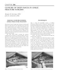
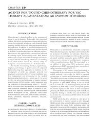
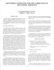
200CHAPTER 33rings are applied to the tibia allowing for enough space forthe posterior leg <strong>and</strong> the ability to potentially convert thebutt frame configuration to a st<strong>and</strong>ard TSF is desired laterduring the postoperative process. Care must be taken toallow enough room for the placement of the foot plate <strong>and</strong>the distal distraction ring with the distracters in place onthe foot. Once the foot plate is in place <strong>and</strong> attached to thetibial rings, the distal distraction plate is fixated thoughthe distal foot area using trans-osseous wires. In some casesit may be possible to use half pins depending on the sizeof the bones to be distracted or compressed.However, trans-osseous wires allow better control ofthe foot during three dimensional distractions althoughthey lack the stiffness characteristics of half pins.Following the application of the distal ring thedistracters are attached. The surgeon may now manuallydistract the foot in the desired direction <strong>and</strong> set the clampson the distracters. The application process is shown inFigures 3-8. At this time the numbers on the distractersare recorded <strong>and</strong> the data entered into the computerprogram. The computer program will provide a printoutfor the patient <strong>and</strong> the surgeon for the daily distractionprocess. It is important that the surgeon underst<strong>and</strong> therotation <strong>and</strong> the length of distraction that will be necessaryfor the numbers to take the deformity in the direction it issupposed to go. When placing the trans-osseous wiresthrough the forefoot, the surgeon must be cautious thatthe attachment sites for the distracters are not used for thewires. There is a limited amount of connection holesbetween the distracter connection holes. Good underst<strong>and</strong>ingof the spatial relationship of the wires <strong>and</strong> thedistracters will help avoid impingement of the two duringthe distraction or compression phase of treatment.INTRAOPERATIVE CAREThe patient <strong>and</strong> the surgeon will distract or compress thedeformity on a daily basis in most cases. Soft tissuedeformities can be distracted at a rate of 1 mm per day ata minimum. It may be possible to distract larger amountsdepending on the patient’s tolerance to pain. Cautionshould be taken to keep from fracturing bone due toexcessive or quick distraction. If an osteotomy has beenmade <strong>and</strong> the distraction is performed to grow bone whilecorrecting the deformity, then the usual rate of 1 mm perday is recommended beginning at approximately 7 dayspostoperative. Soft tissue distraction does not require apostoperative waiting period. Daily pin care is required asis normal with all external fixators. Drainage should beexpected from the distal foot wires as there is a significantamount of tension on the skin during distraction.Distraction will often cause the skin to cut as the wiresmove distally. This area can become irritated <strong>and</strong> needs tobe addressed with daily wound care. Radiographs takenthroughout the postoperative process will allow thesurgeon to check the progress <strong>and</strong> assess any neededcorrections in distraction planes.Following the adequate distraction of the deformitymultiple options become available. In some cases anosteotomy may be used with or without bone grafting.There are instances when the deformity can be pinned inthe new position <strong>and</strong> then compressed with the samefixation intact. The fixator may be reconfigured with thereplacement of the distracters with threaded rods or to ast<strong>and</strong>ard TSF configuration.Figure 3. Dorsal alignment view with the footcentered on the tibial rings.Figure 4. Plantar view showing alignment of the leg <strong>and</strong> foot with theTaylor spatial butt frame.