Installation Instructions for IDH Max Cylindrical Locks - Best Access ...
Installation Instructions for IDH Max Cylindrical Locks - Best Access ...
Installation Instructions for IDH Max Cylindrical Locks - Best Access ...

Create successful ePaper yourself
Turn your PDF publications into a flip-book with our unique Google optimized e-Paper software.
<strong>Installation</strong> <strong>Instructions</strong> <strong>for</strong> 83KW/93KW–85KW/95KW <strong>IDH</strong> <strong>Max</strong> <strong>Cylindrical</strong> <strong>Locks</strong>OverviewThe 83KW/93KW–85KW/95KW <strong>IDH</strong> <strong>Max</strong> <strong>Cylindrical</strong> Lockprovides the following features in an integrated lock,eliminating the need to install separate sensors in andaround the door frame:■ electrified locking mechanism■ electronic token reader■ integrated trim■ door status detection■■ability to exit without triggering an alarmcompatibility with varied access control panels/reader interfaces.Note: For a list of compatible access control panels/reader interfaces, contact your local BEST representative.A panel interface module is provided with the lock. Thepanel interface module receives token data and locksensor data from the lock through an RS-485 connection.It translates this data into parallel signals, which it sendsto the access control panel/reader interface. The panelinterface module also translates control signals receivedfrom the access control panel/reader interface and sendsthem to the lock.The figure below shows the relationship between thecomponents in the <strong>IDH</strong> <strong>Max</strong> system.Power (2)PowersupplyRS-485 Communication (2)ContentsThese installation instructions describe how to install,wire, and configure the components provided with your83KW/93KW–85KW/95KW <strong>IDH</strong> <strong>Max</strong> <strong>Cylindrical</strong> Lock. Thefollowing topics are covered.Site survey................................................................ 2Components checklist............................................. 2Special tools checklist ............................................. 3Preparing the door and door jamb........................ 4Installing the lock and through-bolt trim ........... 11Completing the installation at the door.............. 14Installing the panel interface module ................. 18Testing the installation ......................................... 23Troubleshooting the installation ......................... 24Panel interfacemoduleField wireharnessWiretransferhingeLockSounder (2)Reader LED (2)Token data (2)Strike (2)RQE status (2)Door status (2)Communication tamper (2)Power (2)Card present (1)Powersupply<strong>Access</strong>controlpanel/readerinterfaceBEST ACCESS SYSTEMSIndianapolis, Indiana1
<strong>Installation</strong> <strong>Instructions</strong> <strong>for</strong> 83KW/93KW–85KW/95KW <strong>IDH</strong> <strong>Max</strong> <strong>Cylindrical</strong> <strong>Locks</strong>Site surveyComponents checklistUse the following survey to record in<strong>for</strong>mation about theinstallation site. You need this in<strong>for</strong>mation to determinefield wiring needs, select a power supply, and determinehow to prepare the door <strong>for</strong> the lock.Lock in<strong>for</strong>mationLock function:❑ DDEL–Electrically locked❑ DDEU–Electrically unlockedPower source <strong>for</strong> lock:❑ Separate power supply❑ Power provided through panel interface modulePower source <strong>for</strong> panel interface module:❑ Separate power supply❑ Power provided through access control panelDistance of lock site from lock power source: feetDistance of lock site from panel interface module site:feetDoor in<strong>for</strong>mationDoor handing and bevel:❑ Left hand (LH)❑ Left hand, reverse bevel (LHRB)❑ Right hand (RH)❑ Right hand, reverse bevel (RHRB)Door thickness: inches (1 3/4″ – 2 1/4″ ; 1 3/8″with spacer)Environment in<strong>for</strong>mationAmbient temperature:❑ Is within specifications. See the tables below.This product meets the following Locked Door Outdoortest requirements <strong>for</strong> ANSI/BHMA 156.25:Side of door RangeInside+66°F to +74°F (+19°C to +23°C)Outside–31°F to +151°F (–35°C to +66°C)This product meets the following Full Indoor testrequirements <strong>for</strong> ANSI/BHMA 156.25:Side of doorInside and outsideRange+32°F to +120°F (0°C to +49°C)Use the following checklist to make sure that you have theitems necessary to install the components provided withyour 83KW/93KW–85KW/95KW <strong>IDH</strong> <strong>Max</strong> <strong>Cylindrical</strong> Lock.Components provided in the box:❑ Chassis with outside knob/lever and outside rose linerassembly❑ Inside escutcheon assembly with field wire harness❑ Inside escutcheon access door❑ Inside rose liner with RQE feature❑ Outside escutcheon assembly❑ Inside knob/lever❑ Throw member package❑ Latch❑ Door status switch & magnet assembly❑ Plastic bushing package❑ Escutcheon screw package❑ Panel interface module❑ Strike package❑ Bar code ID sticker (<strong>for</strong> your records)Other items you’ll need:❑ Power supply <strong>for</strong> one <strong>IDH</strong> <strong>Max</strong> <strong>Cylindrical</strong> Lock (ifyou’re providing a separate power supply): regulated;12 volts DC at .85 ampsNote: If you intend to power more than one lock with thesame power supply, calculate the amperage <strong>for</strong> thepower supply by multiplying .85 by the number of<strong>IDH</strong> <strong>Max</strong> <strong>Cylindrical</strong> <strong>Locks</strong> (1.1 by the number of <strong>IDH</strong> <strong>Max</strong>Mortise <strong>Locks</strong>).❑ Power supply <strong>for</strong> the panel interface module (if you’reproviding a separate power supply): 12 volts DC at.1 amp❑ Wire transfer hinge: 8 conductors min.; 28 AWG min.continued2BEST ACCESS SYSTEMSIndianapolis, Indiana
Components checklist<strong>Installation</strong> <strong>Instructions</strong> <strong>for</strong> 83KW/93KW–85KW/95KW <strong>IDH</strong> <strong>Max</strong> <strong>Cylindrical</strong> <strong>Locks</strong>Special tools checklist❑ Field wiring <strong>for</strong> power connections between the lockand power supply or the lock and panel interfacemodule.If you’re powering the lock(s) through the panelinterface module, calculate the total length of thepower wire run by summing:■ The distance from the power supply to the panelinterface module.■ The distance from the panel interface module tothe first door.■ If powering more than one door daisy-chained tothe same power supply, add the total distance ofthe power runs between the doors.If you’re powering the lock(s) using a separate powersupply, calculate the total length of the power wire runby summing:■ The distance from the power supply to the firstdoor.■ If powering more than one door daisy-chained tothe same power supply, add the total distance ofthe power runs between the doors.Refer to the table below to determine the minimumwire gauge based on the number of doors sharing thepower supply and the total length of the wire run.Use the following checklist to make sure that you have thespecial tools necessary to install the componentsprovided with your 83KW/93KW–85KW/95KW <strong>IDH</strong> <strong>Max</strong><strong>Cylindrical</strong> Lock.❑ three (3) to four (4) foot, 3/8″ drill bit❑ KD303 Drill jig❑ T15 TORX® bit driver ‡<strong>Max</strong>imum wire length based onno. of doors daisy-chained to power supplyMinimumwire gauge1 door 2 doors 3 doors 4 doors250 feet 125 feet 75 feet 60 feet 18 AWG400 feet 200 feet 130 feet 100 feet 16 AWG600 feet 300 feet 185 feet 150 feet 14 AWG❑ Field wiring <strong>for</strong> RS-485 communication connectionsbetween the lock and panel interface module(4000 feet maximum):Category 5, shielded twisted pair; 24 AWG min.‡ TORX is a registered trademark of the CamcarDivision of Textron.BEST ACCESS SYSTEMSIndianapolis, Indiana3
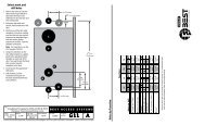
<strong>Installation</strong> <strong>Instructions</strong> <strong>for</strong> 83KW/93KW–85KW/95KW <strong>IDH</strong> <strong>Max</strong> <strong>Cylindrical</strong> <strong>Locks</strong>Preparing the door and door jamb1 Position template and mark drill pointsFigure 1Positioning the template<strong>Installation</strong> templateHorizontal centerlineof lockNote: If the door is a fabricated hollow metal door,determine whether it is properly rein<strong>for</strong>ced to supportthe lock. If door rein<strong>for</strong>cement is not adequate, consultthe door manufacturer <strong>for</strong> in<strong>for</strong>mation on properrein<strong>for</strong>cement. For dimensions <strong>for</strong> preparing metaldoors, see the W14 Template—<strong>Installation</strong>Specifications <strong>for</strong> 83KW/93KW–85KW/95KW <strong>IDH</strong> <strong>Max</strong><strong>Cylindrical</strong> <strong>Locks</strong>.Note: If the door is a LH or RH door, mark the inside ofthe door. If the door is a LHRB or RHRB door, mark theoutside of the door.For uncut doors and frames1 Measure and mark the horizontal centerline of theknob/lever (the centerline <strong>for</strong> the chassis hole) on thedoor and door jamb. Mark the vertical centerline of thedoor edge.Note: The recommended height from the floor to thecenterline of the lock is 38″ .2 Fold the W16 Template—<strong>Installation</strong> Template <strong>for</strong>83KW/93KW <strong>IDH</strong> <strong>Max</strong> <strong>Cylindrical</strong> <strong>Locks</strong> on the dashedline and carefully place it in position on the high sideof the door bevel.Note: For steel frame applications, align the template’shorizontal centerline <strong>for</strong> the latch with the horizontalcenterline of the frame’s strike preparation.3 Tape the template to the door.4 Center punch the necessary drill points. Refer to theinstructions on the template.For doors with standard cylindrical preparation1 Fold the W16 Template—<strong>Installation</strong> Template <strong>for</strong>83KW/93KW <strong>IDH</strong> <strong>Max</strong> <strong>Cylindrical</strong> <strong>Locks</strong> on the dashedline. Looking through the hole from the opposite sideof the door, align the template so that you see thetemplate outline of the 2 1/8″ diameter hole.2 Tape the template to the door.3 Center punch the necessary drill points. Refer to theinstructions on the template.4BEST ACCESS SYSTEMSIndianapolis, Indiana
Preparing the door and door jamb<strong>Installation</strong> <strong>Instructions</strong> <strong>for</strong> 83KW/93KW–85KW/95KW <strong>IDH</strong> <strong>Max</strong> <strong>Cylindrical</strong> <strong>Locks</strong>2 Drill holes and mortise <strong>for</strong> latch face1 Drill the holes listed below:■ upper and lower trim holes—5/8″ diameter— through door■ door status switch & LH/LHRB reader wire hole—7/8″ diameter— through door■ field harness & RH/RHRB reader wire hole—7/8″ diameter— through door■ door status switch hole—1″ diameter— meets door status switch & LH/LHRB reader wirehole■ solenoid wire hole—3/8″ diameter— through door— be<strong>for</strong>e drilling chassis hole■ chassis hole—21/8″ diameter— through door— after drilling solenoid wire hole■ latch hole—1″ diameter— meets chassis holeNote 1: To locate the center of a hole on the oppositeside of the door, drill a pilot hole completely through thedoor.Note 2: For holes through the door, it is best to drillhalfway from each side of the door to prevent the doorfrom splintering.2 Mortise the edge of the door to fit the latch face.Upper trimholeDoor statusswitch holeLatch holeLatch facemortiseFigure 2Inside of doorField harness& RH/RHRBreader wireholeDoor statusswitch & LH/LHRB readerwire holeSolenoid wireholeChassis holeLower trimholeDrilling holes and mortising <strong>for</strong> the latch faceBEST ACCESS SYSTEMSIndianapolis, Indiana5
<strong>Installation</strong> <strong>Instructions</strong> <strong>for</strong> 83KW/93KW–85KW/95KW <strong>IDH</strong> <strong>Max</strong> <strong>Cylindrical</strong> <strong>Locks</strong>Preparing the door and door jambHinge mortiseHole through doorDoor statusswitch hole3 Drill hole <strong>for</strong> field wire harnessCaution 1: Check with your local fire marshalbe<strong>for</strong>e drilling a fire-rated door. Drilling througha fire-rated door may void the fire label.Caution 2: Drill carefully through the door,making sure the drill does not break through theface of the door.1 Remove the hinge nearest to the door status switchhole.2 Using a three (3) to four (4) foot drill bit, drill a 3/8″diameter hole through the door, from the bottom ofthe door status switch hole to the center of the hingemortise.Note: It may be easier to drill halfway from each side ofthe door.Figure 3Inside of doorDrilling the hole <strong>for</strong> the field wire harness4 Prepare <strong>for</strong> wire transfer hinge and runfield wiringField wiring(2 power &2 communication)Door frameFigure 4Preparing <strong>for</strong> the wire transfer hingeHoles <strong>for</strong> spliceconnectorsDoor1 Drill a wire access hole through the frame side of thehinge mortise.2 Drill holes (or pockets) <strong>for</strong> the splice connectors in theframe and door. Refer to the hinge manufacturer’sspecifications <strong>for</strong> the hole location.3 De-burr the holes to prevent damage to the hingeleads.4 Run the power field wiring from the location <strong>for</strong> thelock’s power supply to the location <strong>for</strong> the wiretransfer hinge.Note: For an overview of the system, see the figure onpage 1. For specifications <strong>for</strong> power and communicationfield wiring, see Components checklist, on page 2.5 Run the communication field wiring from the location<strong>for</strong> the panel interface module to the location <strong>for</strong> thedoor transfer hinge.6 Pull the field wiring down the wall and through theaccess hole in the frame.6BEST ACCESS SYSTEMSIndianapolis, Indiana
Preparing the door and door jamb<strong>Installation</strong> <strong>Instructions</strong> <strong>for</strong> 83KW/93KW–85KW/95KW <strong>IDH</strong> <strong>Max</strong> <strong>Cylindrical</strong> <strong>Locks</strong>5 Install latch1 Install the latch in the door.Note: The latch tube prongs should be centered andshould project into the chassis hole.2 Check that the door swings freely.Latch tube prongLatchChassis holeInside of doorFigure 5Installing the latch in the door6 Use drill jig to drill through-bolt holes(9KW only)1 Press the drill jig (KD303) onto the door, engaging itwith the latch tube prongs. Make sure the front edgeof the jig is parallel with the door edge.2 Drill the through-bolt holes (5/16″ diameter) halfwayinto the door.3 Turn the drill jig over and repeat steps 1 and 2 from theopposite side of the door.Note: Replace the drill jig after 10 door preparations.Drill upper throughbolthole.Latch tube prongsDrill lower throughbolthole.Inside of doorFigure 6 Installing the drill jig and drilling thethrough-bolt holesBEST ACCESS SYSTEMSIndianapolis, Indiana7
<strong>Installation</strong> <strong>Instructions</strong> <strong>for</strong> 83KW/93KW–85KW/95KW <strong>IDH</strong> <strong>Max</strong> <strong>Cylindrical</strong> <strong>Locks</strong>Preparing the door and door jambHinge mortiseField harness &RH/RHRB readerwire holeField wireharness7 Pull field wire harness through door1 Feed the field wire harness (connected to the insidetrim) into the field harness & RH/RHRB reader wirehole and down into the hole drilled through the doorto the hinge mortise.2 From the latch edge of the door, fish the field wireharness through the door to the hinge mortise.3 Make sure there are 3″ to 4″ of slack in the field wireharness to allow access to the control electronicscircuit board in the inside trim.Note: You can let the trim dangle from the field wireharness while completing tasks 8 through 14.Inside of doorInside trimFigure 7Pulling the field wire harness through the door8BEST ACCESS SYSTEMSIndianapolis, Indiana
Preparing the door and door jamb<strong>Installation</strong> <strong>Instructions</strong> <strong>for</strong> 83KW/93KW–85KW/95KW <strong>IDH</strong> <strong>Max</strong> <strong>Cylindrical</strong> <strong>Locks</strong>8 Install door status switch and magnet1 On the door jamb, mark the drill point <strong>for</strong> the1″ diameter magnet hole. This hole should be directlyopposite the door status switch reader wire hole whenthe door is closed.2 Drill a 1″ diameter hole <strong>for</strong> the magnet, at least 1 3/4″deep.3 Insert the magnet in the hole.4 Insert the door status switch assembly into the doorstatus switch hole in the edge of the door, feeding theconnectors out the wire hole to the inside of the door,as shown in Figure 8.Wire holeMagnetDoorstatusswitchDoor jambInside of doorFigure 8Installing the door status switch and magnetBEST ACCESS SYSTEMSIndianapolis, Indiana9
<strong>Installation</strong> <strong>Instructions</strong> <strong>for</strong> 83KW/93KW–85KW/95KW <strong>IDH</strong> <strong>Max</strong> <strong>Cylindrical</strong> <strong>Locks</strong>Preparing the door and door jamb9 Install strike box and strike plateStrike boxStrike plate1 In alignment with the center of the latchbolt, mortisethe door jamb to fit the strike box and strike plate.2 Insert the strike box and secure the strike with the twoscrews provided.3 Check the position of the deadlocking plunger againstthe strike plate.Caution: The deadlocking plunger of the latchboltmust make contact with the strike plate, as shownin Figure 9b. The plunger deadlocks the latchboltand prevents someone from <strong>for</strong>cing the latchopen when the door is closed.Door jambFigure 9aInstalling the strike box and strike plateDeadlockingplungerStrike plateFigure 9bAligning the deadlocking plunger with thestrike plate10BEST ACCESS SYSTEMSIndianapolis, Indiana
Installing the lock & through-bolt trim<strong>Installation</strong> <strong>Instructions</strong> <strong>for</strong> 83KW/93KW–85KW/95KW <strong>IDH</strong> <strong>Max</strong> <strong>Cylindrical</strong> <strong>Locks</strong>10 Remove outside knob/lever1 Insert the control key into the core and rotate the key15 degrees to the right.2 Insert a flat blade screwdriver into the figure-8 corehole and into the knob/lever.3 Press the screwdriver blade in the direction of thearrow in Figure 10.Note: You cannot remove the knob/lever if thescrewdriver blade is inserted too far past the keeper.4 Slide the knob/lever off of the sleeve.Knob/lever keeperInsert screwdriverblade here.Figure-8core holeFigure 10Removing the outside knob/lever11 Adjust <strong>for</strong> door thickness1 Determine the door’s thickness.2 Pull the rose locking pin and rotate the outside roseliner until the proper groove on the through-bolt studlines up with the hub face.2 1/4″ groove Throughbolt2″stud1 3/4″Hub faceNote 1: Make sure that the locking pin fully locks intothe rose liner.Note 2: The lockset fits doors 1 3/4″ to 2 1/4″ thick.(A spacer is available <strong>for</strong> 1 3/8″ doors.)Outsiderose linerRose lockingpinFigure 11Adjusting the rose liner <strong>for</strong> the door thicknessBEST ACCESS SYSTEMSIndianapolis, Indiana11
<strong>Installation</strong> <strong>Instructions</strong> <strong>for</strong> 83KW/93KW–85KW/95KW <strong>IDH</strong> <strong>Max</strong> <strong>Cylindrical</strong> <strong>Locks</strong>Installing the lock & through-bolt trimRetractorLatch tubeprongLatchtailpieceLatch tubeprongChassis frameNotchChassis12 Install lock chassis and engageretractor in latchFrom the outside of the door, insert the lock chassisinto the 2 1/8″ chassis hole, routing the solenoid wirethrough the notch.Caution: Make sure that the latch tube prongsengage the chassis frame and that the latchtailpiece engages the retractor.Figure 12Inside of doorInstalling the lock chassis and engaging theretractor in the latch13 Install through-bolts and RQE roseliner1 Place the RQE rose liner on the chassis, aligning theholes in the rose liner with the holes prepared in thedoor.Caution: Make sure that there is clearance <strong>for</strong> thesolenoid wire between the RQE rose liner and thedoor.2 Install the through-bolts through the RQE rose linerand door in the top and bottom holes.3 Tighten the RQE rose liner on the door with thethrough-bolts.Through-boltRQE wireRQE rose linerSolenoid wireFigure 13RQE roselinerInside of doorInstalling the through-bolts and RQE rose linerNote: You do not need to change the positions of theDIP switches on the control electronics circuit boardlocated in the inside escutcheon.■ By default, s witches 1 through 5 are set to ON. Theseswitches are <strong>for</strong> possible future applications.■ By default, switches 6 and 7 are set to ON <strong>for</strong>automatic baud rate detection. This setting lets youdetermine the baud rate <strong>for</strong> communication betweenthe lock’s control electronics circuit board and thepanel interface module by setting DIP switches on thepanel interface circuit board. (See page 22.)■ Switch 8 is set to ON <strong>for</strong> locks with an insertion-typemagnetic stripe card reader; it is set to OFF <strong>for</strong> lockswith any other type of reader.12BEST ACCESS SYSTEMSIndianapolis, Indiana
Installing the lock & through-bolt trim<strong>Installation</strong> <strong>Instructions</strong> <strong>for</strong> 83KW/93KW–85KW/95KW <strong>IDH</strong> <strong>Max</strong> <strong>Cylindrical</strong> <strong>Locks</strong>14 Connect reader wire harness1 For LH and LHRB doorsFrom the outside of the door, feed the reader wireharness connector through the door status switch &LH/LHRB reader wire hole.For RH and RHRB doorsFrom the outside of the door, feed the reader wireharness connector through the field harness &RH/RHRB reader wire hole.Caution: When routing the reader wire harness,make sure the reader wire harness is not routedacross any sharp edges or over any surface thatcould damage its sleeving or wire insulation.2 Temporarily rest the outside trim on the door byinserting the trim studs into the trim holes.3 Connect the reader wire harness to the controlelectronics circuit board in the inside trim.Caution: When connecting the reader wireharness, make sure:■ there are no loose wire connections where thewires are inserted into the reader wireconnector■ the reader wire harness connector is fullyseated in its mating connector on the controlelectronics circuit board.4 From the inside of the door, feed the solenoid andsensor wire harness from the control electronics circuitboard, as well as the sensor wires and the solenoidwire, through the large opening in the inside trim.5 Insert the three bushings into the wire holes, as shownin Figure 14a and Figure 14b.Note: The bushing used on the outside of the doorshould be inserted in the wire hole used in step 1.Reader wire harnessconnectorField harness &RH/RHRB readerwire holeOutside trimBushingDoor status switch& LH/LHRB readerwire holeOutside of doorFigure 14a Feeding the reader wire harness connectorthrough the wire holeReader wire harnessconnectorControl electronicscircuit boardBushingsSolenoid and sensorwire harnessSensor wires andsolenoid wireLarge openingInside trimInside of doorFigure 14b Connecting the reader wire harness to thecontrol electronics circuit boardBEST ACCESS SYSTEMSIndianapolis, Indiana13
<strong>Installation</strong> <strong>Instructions</strong> <strong>for</strong> 83KW/93KW–85KW/95KW <strong>IDH</strong> <strong>Max</strong> <strong>Cylindrical</strong> <strong>Locks</strong>Installing the lock & through-bolt trimFigure 15Inside of doorInside trimCombinationmounting screwMake theseconnections.Standardmounting screwSecuring the through-bolt trim andcompleting connections15 Secure through-bolt trim and completeconnections1 Position the inside and outside trim onto the door.2 Making sure that the trim does not pinch thewires, secure the trim to the door—but do nottighten. Use the combination mounting screw at thetop trim hole and the standard mounting screw at thebottom trim hole.Caution: When routing the solenoid and sensorwire harness, the sensor wires, and the solenoidwires, make sure the wires are not routed acrossany sharp edges or over any surface that coulddamage their sleeving or wire insulation.3 Make the three (3) sensor connections and solenoidconnection, and place the wires into the inside trim.Wire connectionColorNo. ofwiresNo. ofpinsSolenoid Yellow 2 3RQE Brn/Org 2 3Shorting connection Purple 2 2Door status sensor White 2 2Caution: When making the sensor connectionsand solenoid connection, make sure:■ there are no loose wire connections where thewires are inserted into the connectors■ the connectors are firmly mated.14BEST ACCESS SYSTEMSIndianapolis, Indiana
Installing the lock & through-bolt trim<strong>Installation</strong> <strong>Instructions</strong> <strong>for</strong> 83KW/93KW–85KW/95KW <strong>IDH</strong> <strong>Max</strong> <strong>Cylindrical</strong> <strong>Locks</strong>16 Install inside and outside knobs/leversNote: To use a core and throw member from amanufacturer other than BEST with a 9KW Lock, see the<strong>Installation</strong> <strong>Instructions</strong> <strong>for</strong> 9K Non-interchangeableCores & Throw Members (T56093). Skip task 16 andtask 17.1 For the inside and outside knobsPush firmly on the knob until it is seated.For the inside and outside leversWith the handle pointing toward the door hinges,push firmly on the lever until it is seated.2 Tighten the trim mounting screws.3 Turn the knobs/levers to check that they operatesmoothly.Inside of doorFigure 16Installing the knobs/leversBEST ACCESS SYSTEMSIndianapolis, Indiana15
<strong>Installation</strong> <strong>Instructions</strong> <strong>for</strong> 83KW/93KW–85KW/95KW <strong>IDH</strong> <strong>Max</strong> <strong>Cylindrical</strong> <strong>Locks</strong>Completing the installation at the doorFigure 17a Installing the blocking plate and throwmemberThrowmemberCoreControlkeyFigure 17b Installing the coreCoreBlockingplateThrowmember17 Install core and throw member1 Install the blocking plate onto the throw member.Caution: You must use the blocking plate toprevent unauthorized access.2 Insert the control key into the core and rotate the key15 degrees to the right.3 Insert the throw member into the core.4 Insert the core and throw member into the knob/leverwith the control key.5 Rotate the control key 15 degrees to the left andwithdraw the key.Note: Be sure to insert the correct throw member intothe core: 6-pin cores require the number “6” throwmember; 7-pin cores require the number “7” throwmember.Caution: The control key can be used to removecores and to access doors. Provide adequatesecurity <strong>for</strong> the control key.18 Install access door1 Making sure that the access door does not pinchany wires, insert the tabs of the access door into itsmating slots and swing the door closed.2 Use a T15 TORX bit driver to secure the access doorwith the security screw. Tighten firmly.Security screwTabsFigure 18Installing the access door16BEST ACCESS SYSTEMSIndianapolis, Indiana
Completing the installation at the door<strong>Installation</strong> <strong>Instructions</strong> <strong>for</strong> 83KW/93KW–85KW/95KW <strong>IDH</strong> <strong>Max</strong> <strong>Cylindrical</strong> <strong>Locks</strong>19 Install the wire transfer hinge1 Trim the four wires of the field wire harness, which youpulled through the hinge edge of the door in Task 7.Leave sufficient length to connect to the wire transferhinge.2 Splice the power and communication field wiring tothe four pairs of leads on the frame side of the hinge,following the hinge manufacturer’s instructions.3 Splice the four field harness leads (listed in the tablebelow) to the four pairs of leads on the door side of thehinge, matching each pair of leads to itscorresponding field wire.Wire ColorGround Black12 VDC RedCom+ OrangeCom– Green4 Insert the wires and splice connectors into the holes orpockets in the door and frame, being careful not topinch the wires. Install the wire transfer hinge.<strong>Access</strong> holesField wiresSpliceconnectorsWire transferhingeDoor frameFigure 19Installing the wire transfer hingeField wireharness leadsDoor20 Install lock power supply (optional)If you are providing a separate power supply <strong>for</strong> thelock instead of providing power via the panel interfacemodule, connect the two power field wires (run fromthe wire transfer hinge) to the power supply. Makesure power (12 volts DC) and ground are connectedproperly.Follow the instructions provided by the power supplymanufacturer. Do not plug in the power supply yet.Note: For specifications <strong>for</strong> the power supply, seeComponents checklist, on page 2.BEST ACCESS SYSTEMSIndianapolis, Indiana17
<strong>Installation</strong> <strong>Instructions</strong> <strong>for</strong> 83KW/93KW–85KW/95KW <strong>IDH</strong> <strong>Max</strong> <strong>Cylindrical</strong> <strong>Locks</strong>Installing the panel interface module21 Mount panel interface moduleAdhesivetapePeel the paper off the adhesive tape affixed to theback of the panel rail and press the panel rail intoposition.Note: Mount the panel interface module in theenclosure with the access control panel/reader interface,if possible.Figure 21Mounting the panel interface module18BEST ACCESS SYSTEMSIndianapolis, Indiana
Installing the panel interface module<strong>Installation</strong> <strong>Instructions</strong> <strong>for</strong> 83KW/93KW–85KW/95KW <strong>IDH</strong> <strong>Max</strong> <strong>Cylindrical</strong> <strong>Locks</strong>22 Connect field wiring from wire transferhinge to panel interface module1 Connect the two communication field wires (run fromthe wire transfer hinge) to the COM+ and COM–terminals on the panel interface circuit board.Note: The field wire harness leads, connected to the doorside of the wire transfer hinge, are described in the tablebelow.12V GND COM+ COM- 12V GNDJ1<strong>IDH</strong> Panel InterfaceJP2JP3OFF1 2 3 4 5 6 7 8ONON1SW18Wire ColorGround Black12 VDC RedCom+ OrangeCom– GreenJ31TPRJ28 1 9DLS RQE STK D0 D1 RED GRN BPR GND NC NC CPFigure 22a Panel interface circuit board2 If you are providing power to the lock through thepanel interface module, connect the two power fieldwires (run from the wire transfer hinge) to the 12V andGND terminals on the panel interface circuit board.Note: JP2 and JP3, shown in Figure 22a, are used <strong>for</strong>manufacturing purposes only.3 Connect the RS-485 shield wire to one of the GNDterminals on J1.Connect to wiretransfer hinge.12V GND COM+ COM- 12V GNDJ1Figure 22b Connecting field wiring from the wire transferhingeBEST ACCESS SYSTEMSIndianapolis, Indiana19
Installing the panel interface module<strong>Installation</strong> <strong>Instructions</strong> <strong>for</strong> 83KW/93KW–85KW/95KW <strong>IDH</strong> <strong>Max</strong> <strong>Cylindrical</strong> <strong>Locks</strong>Terminals Description Related DIP switchesRED & GRN (on J2)Reader LED inputBPR & GND (on J2)Sounder input12V & GND (on J1)Power inputInput <strong>for</strong> the red and green LED control signal(s) from the access controlpanel/reader interface. This input is configured using DIP switch 1 <strong>for</strong> eitherone-wire LED operation or two-wire LED operation.Two-wire LED operation: Connect the access control panel’s/readerinterface’s red LED output to the RED terminal and the access control panel’s/reader interface’s green LED output to the GRN terminal. The reader’s red LEDturns on when the access control panel/reader interface provides 0 volts DC tothe input <strong>for</strong> the red LED. The reader’s green LED turns on when the accesscontrol panel/reader interface provides 0 volts DC <strong>for</strong> the green LED.One-wire LED operation: Connect the access control panel’s/readerinterface’s LED output to the RED terminal. The reader’s LEDs are controlled asshown below.Input signal LED response0 volts DC Green LED ON5 volts DC Red LED ONNot driven Both LEDs OFFNote: The signals provided to the Reader LED input and the Sounder input mustbe greater than 3.5 volts DC to be interpreted as a 5 volts DC signal. Signals withvoltage less than .8 volts DC are interpreted as 0 volts DC (connection to ground(GND)).Input <strong>for</strong> the sounder control signal from the access control panel/readerinterface. By default, the lock’s sounder turns on when the access controlpanel/reader interface closes the contact <strong>for</strong> the sounder, connecting thepanel interface circuit board’s BPR terminal to ground (GND).Input <strong>for</strong> 12 volts DC at .1 amp power supply.Caution: To prevent damage and injury, connect the power supply afterall other connections have been made.DIP switch 1 configuresthis input <strong>for</strong> one-wireor two-wire operation.DIP switch 7 providesthe ability to invert theinterpretation of thesounder input signal.NoneNote: The two NC terminalson J2 are not used.J2D0 D1 RED GRN BPR GND NC NC CPConnect to access control panel/reader interface.Figure 23b Connecting to the access control panel/reader interfaceConnect to12 VDC at .1 Asupply.12V GND COM+ COM- 12V GNDJ1Figure 23c Connecting to the power supplyBEST ACCESS SYSTEMSIndianapolis, Indiana21
<strong>Installation</strong> <strong>Instructions</strong> <strong>for</strong> 83KW/93KW–85KW/95KW <strong>IDH</strong> <strong>Max</strong> <strong>Cylindrical</strong> <strong>Locks</strong>Installing the panel interface module24 Set panel interface moduleDIP switchesSet DIPswitches.1 2 3 4 5 6 7 8ONSW1Set the DIP switches on the panel interface circuitboard. Refer to the table below. Default settings areshown in boldface.Note: DIP switch 8 is used in <strong>IDH</strong> <strong>Max</strong> Mortiseinstallations. Leave this switch set to ON.25 Set and connect power supplyFigure 24Setting DIP switchesSetting DIP switches1 Make sure that the output voltage of the power supply<strong>for</strong> the panel interface module and lock is set to15 volts DC or lower.2 Make the final power supply connections.3 Adjust the power supply output voltage to13.8 volts DC.Feature Option DIP Switch SettingReader LED input configurationTwo-wire operation Switch 1–ONProvides the ability to select between one-wire and two-wire LEDoperation <strong>for</strong> the reader LED input.One-wire operation Switch 1–OFFBaud rate selection38400 bps Switch 2–OFF Switch 3–OFFProvides the ability to select the baud rate <strong>for</strong> communication between thepanel interface circuit board and the lock’s control electronics circuit board. 19200 bps Switch 2–ON Switch 3–OFFNote: To control the baud rate using DIP switches 2 and 3 on the panel 9600 bps Switch 2–OFF Switch 3–ONinterface circuit board, DIP switches 6 and 7 on the control electronics circuitboard both must be set to ON (automatic baud rate detection).2400 bps Switch 2–ON Switch 3–ONRequest-to-exit (RQE) status output configurationNormally-open (NO) Switch 4–ONProvides the ability to invert the request-to-exit (RQE) status signal. If DIPswitch 4 is ON, the contact is closed when the door knob/lever is turned, Normally-closed (NC) Switch 4–OFFactivating the RQE switch.Door status output configurationNormally-closed (NC) Switch 5–ONProvides the ability to invert the signal <strong>for</strong> the door status output. If DIPswitch 5 is ON, the contact is closed when the door is closed (the door Normally-open (NO) Switch 5–OFFstatus switch is closed).Communication tamper configurationNormally-closed (NC) Switch 6–ONProvides the ability to invert the signal <strong>for</strong> the communication tamperoutput. If DIP switch 6 is ON, the contact is closed when thecommunication connection between the panel interface circuit board andthe lock’s control electronics circuit board is OK.Normally-open (NO) Switch 6–OFFSounder input configurationProvides the ability to invert the interpretation of the sounder input signal.The normal input configuration interprets a closed contact as sounder ON.Normal inputInverted inputSwitch 7–ONSwitch 7–OFF22BEST ACCESS SYSTEMSIndianapolis, Indiana
Testing the installation<strong>Installation</strong> <strong>Instructions</strong> <strong>for</strong> 83KW/93KW–85KW/95KW <strong>IDH</strong> <strong>Max</strong> <strong>Cylindrical</strong> <strong>Locks</strong>Per<strong>for</strong>m the following steps to test the installation. Also,per<strong>for</strong>m any standard testing recommended by themanufacturer of the access control panel. If you encounterproblems, see Troubleshooting the installation, onpage 24.1 Check the control electronics’ green status LED and thepanel interface module’s green status LED.Both LEDs should be blinking, indicating that thecommunication connection between the panelinterface circuit board and the lock’s controlelectronics circuit board is OK.2 After per<strong>for</strong>ming any necessary programming <strong>for</strong> thelock and putting the door in a locked mode, use a validtoken to access the lock.Confirm that the red reader LED, green reader LED, andsounder respond as expected.The lock should allow access, verifying that thesolenoid is working.To check that the reader is working, view the lock’sevent history and verify that the in<strong>for</strong>mation recorded<strong>for</strong> the token is correct.3 Use an invalid token to attempt to access the lock.Confirm that the red reader LED, green reader LED, andsounder respond as expected.The lock should deny access.4 With the door armed, attempt to exit through thedoor.The request-to-exit (RQE) feature should let you exitwithout triggering an alarm by the access controlpanel.5 Remove power from the lock and check whether thedoor remains locked or is unlocked.Verify that the lock fails safe or secure, according to itsfunction.6 With the door armed, hold the door open. Hold amagnet against the edge of the door, over the doorstatus sensor, until the access control panel sees thedoor as closed. Then remove the magnet.Verify that the appropriate alarm response is triggeredby the access control panel, indicating that the doorstatus sensor is working.BEST ACCESS SYSTEMSIndianapolis, Indiana23
<strong>Installation</strong> <strong>Instructions</strong> <strong>for</strong> 83KW/93KW–85KW/95KW <strong>IDH</strong> <strong>Max</strong> <strong>Cylindrical</strong> <strong>Locks</strong>Troubleshooting the installationYou notice . . . Possible causes include . . . You should . . .To troubleshoot installation problems, refer to the tablebelow. For more in<strong>for</strong>mation, refer to the W Series ServiceManual (T60775) and to the documentation provided bythe manufacturer of the access control panel/readerinterface.Control electronics’ green statusLED and panel interface module’sgreen status LED are steadily on.Note: You can check the controlelectronic’s green status LED byremoving the access door from theinside trim. You can see thereflection of the LED inside theupper-left corner of the trim.Control electronics’ green statusLED is off.Panel interface module’s greenstatus LED is off.A ‘door <strong>for</strong>ced’ alarm occurs whensomeone exits through the door.Communication between the lock’scontrol electronics circuit board and thepanel interface circuit board has beeninterrupted.Power is not being supplied to the lock.Power is not being supplied to the panelinterface module.RQE wiring and door status wiring isreversed between the panel interfacemodule and the access control panel/reader interface.Make sure DIP switches 6 and 7 on the lock’scontrol electronics circuit board are both set to ON(automatic baud rate detection) or to the samepositions as DIP switches 2 and 3 on the panelinterface circuit board.Check the connections <strong>for</strong> all communication fieldwiring.Check the communication connections betweenthe field wire harness and the wire transfer hinge.Make sure that the lock’s power supply isconnected to electrical service.Check the connections <strong>for</strong> all power field wiring tothe lock.Check the power connections between the fieldwire harness and the wire transfer hinge.Check the connections <strong>for</strong> power wiring betweenthe panel interface module and the access controlpanel (or other power source).Refer to Connect panel interface module to accesscontrol panel/reader interface, on page 20, andcorrect the wiring problem.24BEST ACCESS SYSTEMSIndianapolis, Indiana© 2002 <strong>Best</strong> Lock Corporation dba <strong>Best</strong> <strong>Access</strong> Systems.T60771/Rev C 1811594 ER-7991-12 May 2002


![B.A.S.I.S. G Service Manual [T63300] - Best Access Systems](https://img.yumpu.com/48375082/1/190x245/basis-g-service-manual-t63300-best-access-systems.jpg?quality=85)