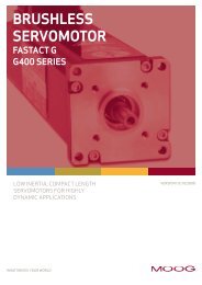
User Manual M3000® Automation System / MSC II (Moog Servo ...
User Manual M3000® Automation System / MSC II (Moog Servo ...
User Manual M3000® Automation System / MSC II (Moog Servo ...

You also want an ePaper? Increase the reach of your titles
YUMPU automatically turns print PDFs into web optimized ePapers that Google loves.
5 Mechanical Installation DIN Rail Modules<br />
6. Push the two red locking slides back into all of the modules. This fixes<br />
the modules onto the DIN top-hat rail, establishes an electrical connection<br />
with the top-hat rail, and locks the modules together with a secure<br />
contact.<br />
Figure 24: Fixing and Locking a DIN Rail Module<br />
5.1.4.2 Removing DIN Rail Modules<br />
WARNING No work of any kind, such as mounting, removing, wiring,<br />
or repairs to the M3000 ® automation system or DIN<br />
rail modules may be performed while the automation<br />
system or the modules are in operation!<br />
There is a danger of:<br />
• Uncontrolled movements<br />
• Permanent damage<br />
• Malfunctions<br />
Before performing any work on the M3000 ® automation system<br />
or DIN rail modules, it is essential that the system is<br />
stopped and the power supply is disconnected.<br />
Therefore, all power supplies must be switched off, including<br />
those from attached peripherals such as externally supplied<br />
transmitters, programming devices, etc.!<br />
No tools are needed to remove DIN rail modules.<br />
Mounting<br />
DIN Rail Modules<br />
Removing DIN Rail<br />
Modules:<br />
Safety Instructions<br />
© <strong>Moog</strong> GmbH <strong>User</strong> <strong>Manual</strong> M3000 ® and <strong>MSC</strong> <strong>II</strong> (CA65865-001; Version 1.1, 08/08) 35