Steering Gears Application Guide - CARQUEST Auto Parts
Steering Gears Application Guide - CARQUEST Auto Parts
Steering Gears Application Guide - CARQUEST Auto Parts
- No tags were found...

You also want an ePaper? Increase the reach of your titles
YUMPU automatically turns print PDFs into web optimized ePapers that Google loves.
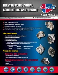
16−POWER STEERING GEARS Sheppard Troubleshooting <strong>Guide</strong>SYMPTOM POSSIBLE CAUSE REMEDYRack on piston damagedReplace parts as requiredDamaged pinion gear on output shaftDamaged output shaft splinesWorn output shaft bushingsWorn pitman arm splinesWorn actuating shaft and valve threadsFree play in miter gears of angle driveDamaged reversing springsUniversal joint yoke loose on actuating shaftReplace pinion gearReplace output shaftReplace bushings and polish shaft to removebronze depositsReplace worn partsReplace worn parts as requiredFollow "Hydraulic Supply−Diagnosis"procedures to locate cause of wearRemove miter gear housing shims to mesh gearsCheck and repair as requiredRepair or replace damaged parts, check forspline wearNo attempt to return straight aheadfrom turnsNo positive caster<strong>Steering</strong> column bind<strong>Steering</strong> gear mounting distortedLinkage ball sockets seized or bindingKing pins seized or bindingKnuckle clearance misadjustOil flow rate incorrectSet to 4" to 6" positive casterCheck and repair universal joints andsupport bearingsShim mounting pads to correct pistonto bore interferenceCheck and repair or replaceRepair or replaceAdjust clearance to specificationsCheck and correct supply pump or controlsNOTE: Thread WearAcme thread wear generally comes from inadequate lubrication or excessive manual steering of the vehicle. Manual steering results frominadequate pump pressure or flow, or an overloaded front axle where you need steering forces in excess of the hydraulic design of the steeringgear.NOTE: FreeplayThe movement of the shuttle type actuating valve within the piston, along with the normal clearances required between operating parts in thesteering gear will produce a certain amount of unresponsive motion at the rim of the steering wheel. This unresponsive motion is inherent to thedesign and must be considered normal. With recent advances in technology and manufacturing methods it has been possible to considerablyreduce the amount of this unresponsive motion. <strong>Steering</strong> gears in service prior to July 1978 could be expected to have 3 1/2 to 4 inchesunresponsive motion. Current production Sheppard steering gears in service will have 1 1/2 to 2 1/2 inches of unresponsive motion. Variouscombinations of steering gear ratios and steering wheel diameters could effectively reduce these maximum allowances. Nominal unresponsivemotion in Series 6 steering gears, measurable at 1/2 to 1 1/2 inches. Unresponsive motion is measured at the rim of the steering wheel. It must,therefore, be noted that any freeplay in the steering column and related components will affect your measurements. The steering gear mountingmust be tight and steering linkage wear adjusted out or worn parts replaced. The vehicle should be standing on a smooth shop floor with the engineidling when unresponsive motion is checked. Measurement is made at the rim of the steering wheel, from initial tire and wheel movement left steer,to initial tire and wheel movement right steer.16 − 34