
Create successful ePaper yourself
Turn your PDF publications into a flip-book with our unique Google optimized e-Paper software.
ENGLISH1 SAFETY . . . . . . . . . . . . . . . . . . . . . . . . . . . . . . . . . . . . . . . . . . . . . . . . . . . . . . . . . . . 42 INTRODUCTION . . . . . . . . . . . . . . . . . . . . . . . . . . . . . . . . . . . . . . . . . . . . . . . . . . . 62.1 Equipment . . . . . . . . . . . . . . . . . . . . . . . . . . . . . . . . . . . . . . . . . . . . . . . . . . . . . . . . . . . . . . . . 63 TECHNICAL DATA . . . . . . . . . . . . . . . . . . . . . . . . . . . . . . . . . . . . . . . . . . . . . . . . . 63.1 <strong>Transmig</strong> <strong>300C</strong> . . . . . . . . . . . . . . . . . . . . . . . . . . . . . . . . . . . . . . . . . . . . . . . . . . . . . . . . . . . . 63.2 <strong>Transmig</strong> <strong>350C</strong> . . . . . . . . . . . . . . . . . . . . . . . . . . . . . . . . . . . . . . . . . . . . . . . . . . . . . . . . . . . . 74 INSTALLATION . . . . . . . . . . . . . . . . . . . . . . . . . . . . . . . . . . . . . . . . . . . . . . . . . . . . 74.1 Placing . . . . . . . . . . . . . . . . . . . . . . . . . . . . . . . . . . . . . . . . . . . . . . . . . . . . . . . . . . . . . . . . . . . 84.2 Assembly of components . . . . . . . . . . . . . . . . . . . . . . . . . . . . . . . . . . . . . . . . . . . . . . . . . . . 84.3 Electrical installation . . . . . . . . . . . . . . . . . . . . . . . . . . . . . . . . . . . . . . . . . . . . . . . . . . . . . . . 84.4 Mains power supply . . . . . . . . . . . . . . . . . . . . . . . . . . . . . . . . . . . . . . . . . . . . . . . . . . . . . . . . 95 OPERATION . . . . . . . . . . . . . . . . . . . . . . . . . . . . . . . . . . . . . . . . . . . . . . . . . . . . . . . 105.1 Connection and control devices . . . . . . . . . . . . . . . . . . . . . . . . . . . . . . . . . . . . . . . . . . . . . 105.2 Function explanation . . . . . . . . . . . . . . . . . . . . . . . . . . . . . . . . . . . . . . . . . . . . . . . . . . . . . . . 116 MAINTENANCE . . . . . . . . . . . . . . . . . . . . . . . . . . . . . . . . . . . . . . . . . . . . . . . . . . . . 116.1 Inspection and cleaning . . . . . . . . . . . . . . . . . . . . . . . . . . . . . . . . . . . . . . . . . . . . . . . . . . . . 117 FAULT TRACING . . . . . . . . . . . . . . . . . . . . . . . . . . . . . . . . . . . . . . . . . . . . . . . . . . . 12DIAGRAM . . . . . . . . . . . . . . . . . . . . . . . . . . . . . . . . . . . . . . . . . . . . . . . . . . . . . . . . . . . . 13WEAR COMPONENTS . . . . . . . . . . . . . . . . . . . . . . . . . . . . . . . . . . . . . . . . . . . . . . . . . 16ACCESSORIES . . . . . . . . . . . . . . . . . . . . . . . . . . . . . . . . . . . . . . . . . . . . . . . . . . . . . . . 18TOCe− 3 −
1 SAFETYUsers of welding equipment have the ultimate responsibility for ensuring that anyone who works onor near the equipment observes all the relevant safety precautions. Safety precautions must meetthe requirements that apply to this type of welding equipment. The following recommendationsshould be observed in addition to the standard regulations that apply to the workplace.All work must be carried out by trained personnel well−acquainted with the operation of the weldingequipment. Incorrect operation of the equipment may lead to hazardous situations which can resultin injury to the operator and damage to the equipment.1. Anyone who uses the welding equipment must be familiar with: its operation location of emergency stops its function relevant safety precautions welding2. The operator must ensure that: no unauthorised person is stationed within the working area of the equipment when it isstarted up. no−one is unprotected when the arc is struck3. The workplace must: be suitable for the purpose be free from draughts4. Personal safety equipment Always wear recommended personal safety equipment, such as safety glasses, flame−proofclothing, safety gloves. Do not wear loose−fitting items, such as scarves, bracelets, rings, etc., which could becometrapped or cause burns.5. General precautions Make sure the return cable is connected securely. Work on high voltage equipment may only be carried out by a qualified electrician. Appropriate fire extinquishing equipment must be clearly marked and close at hand. Lubrication and maintenance must not be carried out on the equipment during operation.T3035Ce− 4 −
WARNINGARC WELDING AND CUTTING CAN BE INJURIOUS TO YOURSELF AND OTHERS. TAKE PRECAU-TIONS WHEN WELDING. ASK FOR YOUR EMPLOYER’S SAFETY PRACTICES WHICH SHOULD BEBASED ON MANUFACTURERS’ HAZARD DATA.ELECTRIC SHOCK − Can kill Install and earth the welding unit in accordance with applicable standards. Do not touch live electrical parts or electrodes with bare skin, wet gloves or wet clothing. Insulate yourself from earth and the workpiece. Ensure your working stance is safe.FUMES AND GASES − Can be dangerous to health Keep your head out of the fumes. Use ventilation, extraction at the arc, or both, to take fumes and gases away from your breathing zoneand the general area.ARC RAYS − Can injure eyes and burn skin. Protect your eyes and body. Use the correct welding screen and filter lens and wear protectiveclothing. Protect bystanders with suitable screens or curtains.FIRE HAZARD Sparks (spatter) can cause fire. Make sure therefore that there are no inflammable materials nearby.NOISE − Excessive noise can damage hearing Protect your ears. Use earmuffs or other hearing protection. Warn bystanders of the risk.MALFUNCTION − Call for expert assistance in the event of malfunction.READ AND UNDERSTAND THE INSTRUCTION MANUAL BEFORE INSTALLING OR OPERATING.PROTECT YOURSELF AND OTHERS!WARNING!Read and understand the instruction manualbefore installing or operating.WARNING!Do not use the power source for thawing frozen pipes.This product is solely intended for arc welding.T3035Ce− 5 −
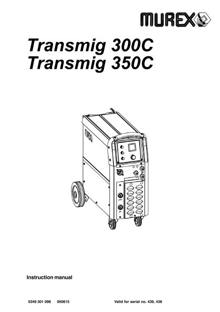
2 INTRODUCTION<strong>Transmig</strong> <strong>300C</strong> & <strong>Transmig</strong> <strong>350C</strong> are step controlled power sources in a compactdesign, intended for welding with solid steel, stainless steel or aluminium wire as wellas tubular wire with or without shielding gas.The possibility of welding with homogeneous wire/shielding gas and welding withgasless tubular wire is obtained by switching the + and − connections on theswitching terminal above the wire feed unit.2.1 EquipmentBoth power sources are supplied with:Return cable 3,5m with return clampShelf for gas cylinderInstruction manual3 TECHNICAL DATA3.1 <strong>Transmig</strong> <strong>300C</strong>VoltagePermissible load at100% duty cycle 150 A/22 V60 % duty cycle 190 A/24 V30 % duty cycle 280 A/28 VSetting range (DC)Open circuit voltageOpen circuit power400−415 V, 3∼ 50/60 Hz30A/15V−280A/28V15−38 V190 WEfficiency 69%Power factor 0.97Control voltageWire feed speed42 V, 50/60 Hz1,9 − 19m/minBurnback time 0 − 0,25sSpot welding 0,2 − 2,5sWelding gun connectionDimensions lxwxhWeightOperating temperatureEURO840x425x83091 kgEnclosure class IP 23Application classification−10 to +40 o CT3035Ce− 6 −
3.2 <strong>Transmig</strong> <strong>350C</strong>VoltagePermissible load at100% duty cycle 195 A/24 V60 % duty cycle 250 A/27 V30 % duty cycle 340 A/31 VSetting range (DC)Open circuit voltageOpen circuit power400−415 V, 3∼ 50/60 Hz40A/16V−340A/31V16−40 V240 WEfficiency 77%Power factor 0.95Control voltageWire feed speed42 V, 50/60 Hz1,9 − 20m/minBurnback time 0 − 0,5sCreep start2/4 stroke 2 / 4Welding gun connectionDimensions lxwxhWeightOperating temperatureOFF / ONEURO840x425x830114 kgEnclosure class IP 23Application classification−10 to +40 o CDuty cycleThe duty cycle refers to the time as a percentage of a ten−minute period that you can weld at a certainload without overloading.Enclosure classThe IP code indicates the enclosure class, i. e. the degree of protection against penetration by solidobjects or water. Equipment marked IP23 is designed for indoor and outdoor use.Application classThe symbol indicates that the power source is designed for use in areas with increasedelectrical hazard.4 INSTALLATIONThe installation must be executed by a professional.WARNING!This product is intended for industrial use. In a domestic environment this product may cause radiointerference. It is the user’s responsibility to take adequate precautions.T3035Ce− 7 −
4.1 PlacingPosition the welding power source such way that its cooling air inlets and outlets arenot obstructed.4.2 Assembly of componentsWARNING!During transport, the rear wheels of the power source are in their forward position.Before use, place the wheels in their rear position.4.3 Electrical installationT3035Ce− 8 −
4.4 Mains power supplyCheck that the unit is connected to the correct mains power supply voltage, and thatit is protected by the correct fuse size. A protective earth connection must be made,in accordance with regulations.Rating plate with supply connection data<strong>Transmig</strong> <strong>300C</strong> 3∼ 50/60 Hz <strong>Transmig</strong> <strong>350C</strong> 3∼ 50/60 HzVoltage V 400/415 Voltage V 400/415Current Aat 100% duty cycle 7Current Aat 100% duty cycle 9at 60% duty cycle 10 at 60% duty cycle 14at 30% duty cycle 18 at 30% duty cycle 21Cable area mm 4 x 1.5 Cable area mm 4 x 2.5Fuse slow A 16 Fuse slow A 16T3035Ce− 9 −
5 OPERATIONGeneral safety regulations for the handling of the equipment can be found onpage 4. Read through before you start using the equipment!WARNING!Rotating parts can cause injury, take great care.WARNING − TIPPING RISK!There is a risk of tipping while transportation and operation, if the welding machine leansmore than 10 o . In that case appropriate securing has to be provided !5.1 Connection and control devices1 Mains supply switch 8 Connection for return cable (−), low inductance2 Switch, coarse control 9 Knob for selecting − creep start − ON/OFF3 Switch, precise control 10 Knob for wire speed setting4 Indicating lamp, power supply ON 11 Knob for selecting 2/4−stroke control mode5 Orange indicating lamp, overheating 12 Knob for burn−back time setting6 EURO − connector (for welding gun) 13 Digital instrument − V / A(option,see page 18)7 Connection for return cable (−), high inductance14 Knob for spot welding − ON/OFF and timesettingT3035Ce− 10 −
5.2 Function explanation5.2.1 Overheating protectionA thermal overload cutout protects against overheating. The cutout resets automaticallywhen the unit has cooled.5.2.2 Inductance connectionHigher inductance produces a more flowing weld and fewer spatters. Lower inductanceproduces a harsher sound and a stable, concentrated arc.6 MAINTENANCERegular maintenance is important for safe, reliable operation.Note!All guarantee undertakings from the supplier cease to apply if the customer himselfattempts any work in the product during the guarantee period in order to rectify anyfaults.6.1 Inspection and cleaningCheck regularly that the power source is free from dirt.The power source should be regularly blown clean using dry compressed air at reducedpressure. More frequently in dirty environments.Otherwise the air inlet/outlet may become blocked and cause overheating. To avoidthis you can use an airfilter.The airfilter is an accessory. Ordering number can be found on page 18.Welding gunCleaning and replacement of the welding gun’s wear parts should take place atregular intervals in order to achieve trouble−free wire feed. Blow the wire guideclean regularly and clean the contact tip.The brake hubThe hub is adjusted when delivered, ifreadjustment is required, follow the instructionsbelow. Adjust the brake hub so that wire is slightlyslack when wire feed stops.Adjusting the braking torque: Turn the red handle to the locked position. Insert a screwdriver into the springs in the hub.Turn the springs clockwise to reduce the braking torqueTurn the springs anticlockwise to increase the braking torque. NB: Turn bothsprings through the same amount.T3035Ce− 11 −
7 FAULT TRACINGTry these recommended checks and inspections before sending for an authorised service technican.Type of faultActionsNo arc Check that the mains power supply switch is turned on. Check that the welding current supply and return cables arecorrectly connected. Check that correct current value is set.Welding current is interruptedduring weldingThermal overload tripsoperate frequentlyCheck whether the thermal overload trip has operated(indicated by the orange lamp on the front).Check the main power supply fuses.Check to see whether the air filters are clogged.Make sure that you are not exceeding the rated data for thepower source (i.e. that the unit is not being overloaded).Poor welding performance Check that the welding current supply and return cables arecorrectly connected. Check that the correct current value is set. Check that the correct welding wires are being used. Check the main power supply fuses.Check the wire feed unit − if proper rolls are applied andproperly set the pressure of the wire feeder’s pressure rollers<strong>Transmig</strong> <strong>300C</strong>, <strong>Transmig</strong> <strong>350C</strong> is designed and tested in accordance with the internationaland European standards IEC/EN 60974−1 and EN 50199. It is the obligation of theservice unit which has carried out the service or repair work to make sure that the productstill conforms to the said standard.T3035Ce− 12 −
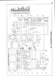
Diagram<strong>Transmig</strong> <strong>300C</strong>, 400−415VdT3035C− 13 −
<strong>Transmig</strong> <strong>350C</strong>, 400−415VdT3035C− 14 −
<strong>Transmig</strong> <strong>300C</strong>/<strong>350C</strong>Valid for serial no. 439, 438−XXX−XXXXOrdering numbers0349 307 690 <strong>Transmig</strong> <strong>300C</strong> 400−415V 350/60Hz0349 307 660 <strong>Transmig</strong> <strong>350C</strong> 400−415V 350/60HzoT3035C− 15 −Edition 050615
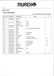
<strong>Transmig</strong> <strong>300C</strong>Wear components(W. F. Mechanism 0455 890 888)Item Denomination Ordering no. NotesA Pressure roller 0455 907 001BFeed roller0367 556 0010367 556 0020367 556 0060367 556 004Ø 0.6−0.8mm Fe, Ss, cored wire.Ø 0.8−1.0mm Fe, Ss, cored wire.Ø 1.0−1.2mm cored wire.Ø 1.0−1.2mm Al wire.C Inlet nozzle 0466 074 001DInsert tube0455 894 0010455 889 001Plastic, must be used together with item 0455 885 001,for welding with Al wire.Steel, must be used together with item 0455 886 001.EOutlet nozzle0455 885 0010455 886 001Must be used together with item 0455 894 001,for welding with Al wire.Must be used together with item 0455 889 001.The rollers are marked with wire dimension in mm, some are also marked with inch.Welding with aluminium wires.In order to weld with aluminium wires, proper rollers, nozzles and liners foraluminium wires MUST be used. It is recommended to use 3m long welding gun foraluminium wires, equipped with appropriate wear parts.wT<strong>300C</strong>− 16 −Edition 050615
<strong>Transmig</strong> <strong>350C</strong>Wear components(W. F. Mechanism 0455 890 881)Item Denomination Ordering no. NotesAPressure roller0369 728 0010466 262 001 KnurledBFeed roller0369 557 0010369 557 0020369 557 0030369 557 0040369 557 006Ø 0.6−0.8mm Fe, Ss, cored wire.Ø 0.8−1.0mm Fe, Ss, cored wire.Ø 1.0−1.2mm Fe, Ss, cored wire.Ø 1.0−1.2mm cored wire, knurled.Ø 1.0−1.2mm Al wire.C Inlet nozzle 0466 074 001DInsert tube0455 894 0010455 889 001Plastic, must be used together with item 0455 885 001,for welding with Al wire.Steel, must be used together with item 0455 886 001.EOutlet nozzle0455 885 0010455 886 001Must be used together with item 0455 894 001,for welding with Al wire.Must be used together with item 0455 889 001.The rollers are marked with wire dimension in mm, some are also marked with inch.Welding with aluminium wires.In order to weld with aluminium wires, proper rollers, nozzles and liners foraluminium wires MUST be used. It is recommended to use 3m long welding gun foraluminium wires, equipped with appropriate wear parts.wT<strong>350C</strong>− 17 −Edition 050615
<strong>Transmig</strong> <strong>300C</strong>/<strong>350C</strong>AccessoriesDigital meter . . . . . . . . . . . . . . . . . . . . . . . . . . . . 0349 308 400Transformer kit for CO 2 heater . . . . . . . . . . . 0349 308 890Filter . . . . . . . . . . . . . . . . . . . . . . . . . . . . . . . . . . . 0349 302 599Cable holder . . . . . . . . . . . . . . . . . . . . . . . . . . . . 0349 303 362aT3035C− 18 −Edition 050615