

SS03010 - Measurement Solutions - FMC Technologies
SS03010 - Measurement Solutions - FMC Technologies
SS03010 - Measurement Solutions - FMC Technologies

Create successful ePaper yourself
Turn your PDF publications into a flip-book with our unique Google optimized e-Paper software.
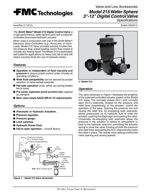
Issue/Rev. 0.7 (8/12)Valve and Line AccessoriesModel 215 Wafer Sphere3"-12" Digital Control ValveSpecificationsBulletin <strong>SS03010</strong>The Smith Meter ® Model 215 Digital Control Valve isa high-performance, wafer-sphere valve with a solenoidcontrolledpneumatic/hydraulic actuator.When used in conjunction with one of the Smith Meter ®Electronic Valve Controllers (e.g., AccuLoad, or micro-Load). Model 215 Valve provides precise, trouble-free,low pressure drop, preset loading, and/or flow control ofvirtually any flowing liquid. The Model 215 is particularlywell suited for applications on heavy fuel oils or lube oilswhere viscosity limits the use of hydraulic valves.FeaturesOperation is independent of fluid viscosity andpressure to assure proper control under virtually alloperating conditions.Wide fluid compatibility can be assured by properselection of valve-wetted materials.Fail-safe operation since valves are spring-loadedfail-to-close.Pre-wired, explosion-proof junction box suppliedas standard.Main valve meets NACE MR-01-75 requirements.OptionsPneumatic or Hydraulic Actuation.Pressure regulator.Pressure gauge.Limit switches.Hydraulic Power Pack.Fail to open operation – consult factory.Customer to ConnectAir or Hydraulic SupplyPressure Gauge (Optional)3" Model 215OperationThe valve schematic in Figure 1 illustrates the simplicityof the solenoid-controlled actuator system of the Model215 Valve. The normally closed (N.C.) and normallyopen (N.O.) solenoids, located on the pressure andrelief lines (respectively) of the actuator, control theoperation of the valve. Opening the pressure line andclosing the relief line, by energizing both solenoids,allows pressurized air or hydraulic fluid to enter theactuator, pushing the diaphragm and opening the valve.Conversely, de-energizing both solenoids allows thepressure in the actuator to relieve to atmosphere orback to the hydraulic reservoir, permitting the actuatorspring to close the valve. Closing off both the pressureand relief lines (energizing the N.O. solenoid only) locksthe valve in place. The needle valve settings control thevalve opening and closing speeds.N.C.SolenoidN.O.SolenoidPressureRegulator(Optional)NeedleValveNote: Valve normally closed.NeedleValveTo Atmosphere(Air)To Tank(Hydraulic)LimitSwitch(Optional)Figure 1 – Model 215 Valve SchematicThe Most Trusted Name In <strong>Measurement</strong>
Specifications (For standard Wafer Sphere Type215 Valve)Main ValveType: High-performance, wafer-sphere valve – standard.Sizes: 3" to 12", installed between Class 150 ANSI RFcompanion flanges (supplied by others).Operating Pressures: 285 psig (Class 150 ANSI) –standard. Other pressures available on request.Operating Temperatures: -20°F (-29°C) to 100°F (38°C) 1 .Materials of Construction:Body – Carbon Steel (optional: Stainless Steel)Disk and Shaft – Stainless SteelSeat – PTFE 2Other materials available on request.Meets NACE MR-01-75 requirements.ActuatorType: Spring – diaphragmMaterials of Construction:Body – Carbon steelDiaphragm – Buna-NAir Supply: Clean, dry air or gaseous nitrogen.Hydraulic Supply: Clean Hydraulic Fluid, Dextron II orequivalent.Operating Pressure: 100 psig maximum, 60-85 psignormal.Operating Temperature: -20°F (-29°C) to 150°F (68°C).Needle ValveMaterial: Brass – standardStainless Steel – optionalTubing and FittingsMaterial: Steel – standardStainless Steel – optionalOptional EquipmentPressure Regulator: 0-250 psi (air only)Pressure Gauge: 0-160 psiOptional Limit Switches: Two SPDT, UL-listed, CSAcertified FM approved. (NEMA 4, 7 Groups C andD, and 9 Groups E, F, and G) for combined watertightand hazardous location design. Switches arerated at 15A with 125/250 Vac and 0.5A dc resistive.Hydraulic Power Pack*• 110/240 VAC 50/60 Hz Single Phase.• 1 HP Explosion Proof Motor – Class I, Div. IGroups C&D.• 3.0 GPM gear pump for fast response.• Hydraulic Supply and Return Manifolds – Drivesup to 6 valves less than or equal to 3" in size.Size 3/8" SAE for supply and 1/2" SAE for return.• 5 Gallon Reservoir – with top filler/breather, drainplug and sight-level (small footprint).• Supply Pressure Regulator – with adjustable setpoint 0 to 200 psig with liquid filled gauge.• On Demand – Pump activates only when valvecontrol is needed, used in conjunction with anAccuLoad or other preset controller.* Consult factory on valves larger than 4".SolenoidsExplosion-proof, UL-listed and CSA-certified for NEMA4 and 7, Groups C and D, for use in watertight andhazardous locations.Type: 2-way normally closed on pressure line2-way normally open on exhaust lineMaterials of Construction:Standard – Brass with Buna-N diskOptional – Stainless Steel with Viton disk for servicein corrosive atmosphereOperating Pressure: 85 psi maximumOperating Temperature: -40°F (-40°C) to 180°F (82°C)Voltage: Standard – 102-120 Vac 60 Hz94-110 Vac 50 Hz204-240 Vac 60 Hz188-220 Vac 50 HzOptional – 20-25 Vdc10.2-12.6 VdcOther voltages, consult factoryApplications: Open or closed position indication forsignaling devices, panel light operation, etc.Valve open position limiting to facilitate prompt valveclosure in dedicated service where an Electronic Controlleris not required.1 Higher temperatures up to 400°F (200°C) available with deratedmaximum working pressure. The operating differential pressureis needed to determine maximum operating temperature (Inletpressure – outlet pressure).2 Polytetrafluoroethylene (PTFE).Page 2 • <strong>SS03010</strong> Issue/Rev. 0.7 (8/12)


