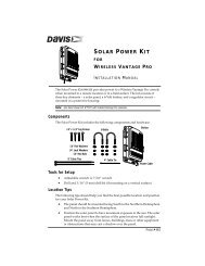
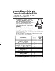
Daytime Fan-Aspirated Radiation Shield Kit Installation Manual
Daytime Fan-Aspirated Radiation Shield Kit Installation Manual
Daytime Fan-Aspirated Radiation Shield Kit Installation Manual
- No tags were found...

You also want an ePaper? Increase the reach of your titles
YUMPU automatically turns print PDFs into web optimized ePapers that Google loves.
Installing the <strong>Daytime</strong> <strong>Fan</strong> <strong>Kit</strong>3. Remove the rain collector cone from the ISSbase by rotating the cone counter-clockwise.When the cone’s latches line up with openingsin the base, you can lift the cone off. The conefits in the base tightly and may require extrapressure to remove the first few times.Steady the ISS base between your knees whenremoving the coneTwist to Open4. Remove the three 8-32 x 4'' screwsholding the radiation shield platestogether.5. Save these three screws andwashers, and separate out theradiation plating.Depending on the placement of theTemperature/Humidity sensor, youmay need to reorient the sensorbefore assembling the lower sectionof the radiation plating. See CheckTemperature/Humidity SensorOrientation on page 5 for moreinformation.PlatesScrewLock asherFlat asherRemove the RainCollector ConeRain Collector aseTemperature/HumiditySensorStandard <strong>Radiation</strong> <strong>Shield</strong> AssemblyNote: Placement of the Temperature/Humidity Sensor may vary.4
Installing the <strong>Daytime</strong> <strong>Fan</strong> <strong>Kit</strong>3. Reinstall the sensor face down on theradiation plate, using the two 1'spacers and #4 screws included withthe kit.4. Put the cable clamp back on thecable and use the screw and flatwasher to resecure the cable onto theradiation plate.5. Replace the radiation plate back inits correct place in the radiationshield plating stack.#4 Screws (2)Temperature/HumiditySensorSpacers (2)Cable ClampReinstall the Temperature/Humidity Sensor — For Sensors on theInsulating Disk1. Locate the plate at the top of theradiation shield plating and find theinsulating disk with theTemperature/Humidity sensor onthe underside of the radiationshield.2. Remove the three screws, flatwasher, and cable clamp securingthe Temperature/Humidity sensor tothe insulating disk. Save the smallscrew, flat washer, and cable clampfor use later.3. Remove the two screws holding theinsulating disk attached on theunderside and discard the disk.4. Reinstall the sensor face down onthe second to bottom-most radiationplate, using the two 1' spacers and#4 screws included with the kit.(Seeillustration above.)Reinstalling Temperature/HumiditySensor with Sensor Mounted DownTemperature/HumiditySensorInsulatingDiskCableClampRemoving Temperature/HumiditySensor with Sensor Mounted onInsulating Disk6
Installing the <strong>Daytime</strong> <strong>Fan</strong> <strong>Kit</strong>5. Put the cable clamp back on the cable and use the screw and flat washer toresecure the cable onto the radiation plate.6. Replace the radiation plate back in its correct place in the radiation shieldplating stack.Assemble the Lower SectionOnce the existing radiation shield has been disassembled and theTemperature/Humidity sensor has been mounted correctly in the radiationplating stack, the existing disks have to be re-organized and assembled withthe fan-aspirated kit. To reassemble the radiation shield with the newfan-aspirated shielding:1. Locate the plate at the topof the radiation shieldplating and find theinsulating disk on theunderside of the radiationshield.2. Remove the two screwsTop Plateholding insulating diskattached on the undersideand discard it. Save the topplate for use in Step 3.Insulating Disk3. Start building the lowersection of the new radiationshield, starting with theoriginal bottom plate onRemove the Insulating Diskbottom and thedisassembled top plate above that.4. Place the plate containing the Temperature/Humidity sensor and the twoopen plates on top of the two bottom plates.Note:When stacking plates, make sure the screw bosses (holes) line up with each other.5. Place the third open plate (supplied with the fan-aspirated kit) on the stack.7
Installing the <strong>Daytime</strong> <strong>Fan</strong> <strong>Kit</strong>8. Attach the three threaded spacers to the fan plate using the three #8-32 x1/2'' screws and the three #8 washers and #8 lock washers included withthe kit.ThreadedSpacer(3)<strong>Fan</strong> Plate#8 Flat Washer#8 Split-Lock Washer#8-32 x 1/2" ScrewInstall Threaded Spacers9. Detach the fan motor cable from the power cable assembly on the fan plateand set the fan motor aside.<strong>Fan</strong> MotorAssembly<strong>Fan</strong> Plate<strong>Fan</strong> PlugPower CableAssemblyDetach <strong>Fan</strong> Motor Cable10. Lower the <strong>Fan</strong> Plate onto the radiation shielding stack.9
Installing the <strong>Daytime</strong> <strong>Fan</strong> <strong>Kit</strong>11. Bring the Temperature/Humidity cable over the top of the fan plate so thatno slack in the cable exists between the sensor and the fan plate and press itfirmly into the cable channel on the fan plate.Lift <strong>Fan</strong> Motor upand set aside<strong>Fan</strong> PlateChannelTemperature/HumidityCableConnecting the <strong>Radiation</strong> <strong>Shield</strong> and <strong>Fan</strong> Unit10
Installing the <strong>Daytime</strong> <strong>Fan</strong> <strong>Kit</strong>12. Place one of the 4''screws removedfrom the originalradiation shield andits corresponding #8lock washer and # 8flat washer into oneof the radiationshield plate holes onthe fan plate locatedjustcounter-clockwisefrom a threadedspacer, making surethe screw goesthrough the boss ineach of the platesand lines up with thethreaded insertlocated in thebottom plate.13. Turn the screw toengage the threadedinsert in the bottomplate.14. Make sure the otherscrew bosses arealigned and theninsert the other two4'' screws and correspondingwashers inthe same way.15. Tighten all threescrews to securelyfasten the bottom section of the radiation shield.#8 Lock Washer#8 Flat WasherInstalling the <strong>Fan</strong> Plate onto the<strong>Radiation</strong> <strong>Shield</strong>#8-32 x 4" Screws (3)<strong>Fan</strong> PlateScrew BossThreaded Insertin Bottom Plate16. Place the fan motor back into place and plug the fan motor cable back intothe power cable assembly.17. Unscrew the cable clamp holding the power cable assembly in place.18. Thread the Temperature/Humidity cable into the cable clamp and tightenthe screw back down in its original placement.19. Place the cap plates on top of the rest of the radiation shield and line uptheir bosses.11
Installing the <strong>Daytime</strong> <strong>Fan</strong> <strong>Kit</strong>20. Insert one of the 3 1/4'' screws and corresponding lock and flat washersincluded in the kit hardware into the ISS base<strong>Radiation</strong> <strong>Shield</strong> Mounting Holes (3)<strong>Radiation</strong> <strong>Shield</strong> Mounting Holes in ISS base12
21. Lower the ISS baseonto the stack so thatthe screw goes into theboss. Turn the screw afew times to engagethe threads.22. Place a lock washerand flat washer on theother two 3 1/4''screws then insertthem through the othertwo screw holes.23. Tighten all threescrews to securelyfasten the radiationshield to the ISS base.Re-Install the ISS1. Install the raincollector cone and lockit in place.2. Slide theTemperature/Humiditycable and thefan-aspirated unit’ssolar power cableassembly through thecable access port of theSIM box.3. Connect theTemperature/Humiditysensor cable.#8-32 x3-1/4" Screws (3)#8 Lock Washers#8 Flat WashersTemperature/HumidityCablePower CableAssemblyInstalling the <strong>Daytime</strong> <strong>Fan</strong> <strong>Kit</strong>Insert front screwfirstSIM HousingISS BaseClosed Cap PlateOpen Cap Plate(hole in center)<strong>Fan</strong> PlateReconnecting the <strong>Radiation</strong> <strong>Shield</strong> to theRain Collector4. Close the SIM cover temporarily without connecting the solar panelcables.5. Test communication between the ISS and the console. To testcommunication, take the console out of Setup Mode and make sure theconsole is receiving data from the ISS. See the ISS manual for moreinformation on testing communication.6. Reinstall the ISS in its previous location.7. Open the SIM cover and connect the WIND (anemometer) cable.8. Cabled ISS Only: Connect the console cable.13
Installing the <strong>Daytime</strong> <strong>Fan</strong> <strong>Kit</strong>9. Connect the wire coming from the top solar panel on the SIM coverincluded in the components of the fan-aspirated unit to the SIM board.Note:This wire is not needed on cabled Vantage Pro2. For cabled systems, you shouldsecure it where it will not interfere with the SIM box.Top PanelWireSensorInterfaceModule(SIM)SIMCoverTemperature/HumidityCablePower CableAssemblyBottom PanelWireConnecting the Solar Panel Wires10. Connect the wire coming from the bottom solar panel to power cableassembly in the SIM Box.11. Reinsert the foam into the cable access port in the SIM box.12. Close the SIM box.13. Use cable ties to secure cables.14. Make sure the fan blades are rotating by directing the connected SIM coverto sunlight or by shining a bright incandescent light on the solar panel.You should hear a slight whir if the fan is running.Guidelines for Securing Cables• Secure cables so they will not whip in the wind.• Secure cables to metal poles by using a cable tie orby wrapping electrical tape around them both.Cable Tie• Place clips or ties approximately every 3 to 5 feet Cable Clip(1 to 1.6 m).Securing Cables• If needed, additional cable ties, cable tie mounts,and other hardware can be obtained at a hardware or electronics store.Note:Do not use metal staples or a staple gun to secure cables. Metal staples—especiallywhen installed with a staple gun—have a tendency to cut the cables.14
MaintenanceTake the Console Out of Setup Mode1. At your Vantage Pro2 console, press and hold DONE for three seconds totake the console out of Setup Mode.2. Check the console for erroneous rain data and clear if necessary.To clear erroneous daily rain data:• Select the RAINDAY button. The graph icon displays next to the dailyrain variable.• Press and release 2ND, then immediately press and hold CLEAR.• The daily rain variable will start blinking.• Keep holding CLEAR until the reading changes to zero.• Refer to your Vantage Pro2 Console <strong>Manual</strong> for more information onclearing any other weather variables or clearing all weather variables inthe console.3. Congratulations! You have completed the upgrade and can now enjoy yourdaytime fan-aspirated radiation shield.Maintenance• Keep the surfaces of the ISS clean, since the radiation shield and solar panelare less effective when dirty. Remove dust from the solar panel and radiationshield with a damp cloth.• Remove any debris obstructing air flow through the radiation shield such asleaves, twigs, webs, and nests.• Do not spray the ISS with insecticides of any kind. Some insecticides candamage the sensors and even damage the radiation shield.Annual MaintenanceWe recommend cleaning out any debris that may have accumulated inside theradiation shield and replacing the motor (# 7758) on an as needed basis. Theroutine procedures for annual maintenance include:1. Remove your fan-aspirated ISS and place on a stable work surface.2. Check to see if the fan motor is still working. If it is not running, replacethe motor with a new motor (# 7758).3. Disassemble the radiation shield.4. Remove any debris lodged inside the unit.5. Clean the surfaces of the radiation shield with a damp cloth.6. Assemble the radiation shield.7. Re-install the ISS in its previous location.15