M-12-30 Cab Switch for DMD Liftgates - Maxon
M-12-30 Cab Switch for DMD Liftgates - Maxon M-12-30 Cab Switch for DMD Liftgates - Maxon
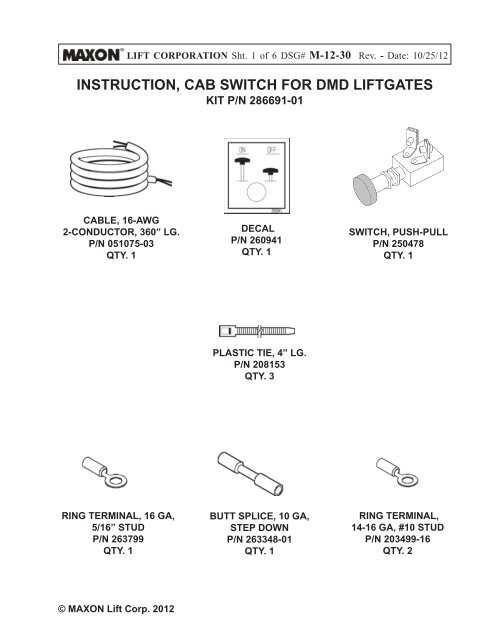
LIFT CORPORATION Sht. 1 of 6 DSG# M-12-30 Rev. - Date: 10/25/12INSTRUCTION, CAB SWITCH FOR DMD LIFTGATESKIT P/N 286691-01CABLE, 16-AWG2-CONDUCTOR, 360” LG.P/N 051075-03QTY. 1DECALP/N 260941QTY. 1SWITCH, PUSH-PULLP/N 250478QTY. 1PLASTIC TIE, 4” LG.P/N 208153QTY. 3RING TERMINAL, 16 GA,5/16” STUDP/N 263799QTY. 1BUTT SPLICE, 10 GA,STEP DOWNP/N 263348-01QTY. 1RING TERMINAL,14-16 GA, #10 STUDP/N 203499-16QTY. 2© MAXON Lift Corp. 2012
- Page 3 and 4: LIFT CORPORATION Sht. 3 of 6 DSG# M
- Page 5 and 6: LIFT CORPORATION Sht. 5 of 6 DSG# M
LIFT CORPORATION Sht. 1 of 6 DSG# M-<strong>12</strong>-<strong>30</strong> Rev. - Date: 10/25/<strong>12</strong>INSTRUCTION, CAB SWITCH FOR <strong>DMD</strong> LIFTGATESKIT P/N 286691-01CABLE, 16-AWG2-CONDUCTOR, 360” LG.P/N 051075-03QTY. 1DECALP/N 260941QTY. 1SWITCH, PUSH-PULLP/N 250478QTY. 1PLASTIC TIE, 4” LG.P/N 208153QTY. 3RING TERMINAL, 16 GA,5/16” STUDP/N 263799QTY. 1BUTT SPLICE, 10 GA,STEP DOWNP/N 263348-01QTY. 1RING TERMINAL,14-16 GA, #10 STUDP/N 203499-16QTY. 2© MAXON Lift Corp. 20<strong>12</strong>
LIFT CORPORATION Sht. 3 of 6 DSG# M-<strong>12</strong>-<strong>30</strong> Rev. - Date: 10/25/<strong>12</strong>4. Align hole in decal (FIG. 3-1) with the10 mm hole <strong>for</strong> mounting the switch.Attach decal to panel as shown inFIG. 3-1.10 MM HOLEFOR SWITCHATTACHING SWITCH DECALFIG. 3-15. In the vehicle cab, crimp the 16 ga, #10 ringterminals (Kit items) to the BLACK wire andWHITE wire on the 2-conductor cable (Kititem) (FIG. 3-2). Then, attach the BLACKwire and WHITE wire to the terminals on thecab switch (FIG. 3-2).14-16 AWGRING TERMINALS(2 PLACES)BLACK WIREWHITE WIRECRIMPING IN-CAB SWITCHWIRING TO TERMINALSFIG. 3-2© MAXON Lift Corp. 20<strong>12</strong>
LIFT CORPORATION Sht. 4 of 6 DSG# M-<strong>12</strong>-<strong>30</strong> Rev. - Date: 10/25/<strong>12</strong>6. To attach the switch to vehicle cab, turnthe knob and hex nut counter-clockwiseto remove from switch (FIG. 4-1). Insertswitch bushing through 10 mm hole inpanel. Turn pal nut to adjust the distancethe bushing protrudes from panel. Reinstallhex nut to attach switch to panel.Then, reinstall knob.BUSHINGDECALKNOBPAL NUTHEX NUTATTACHING SWITCH TO PANELFIG. 4-17. Unbolt main housing cover as shown inFIG. 4-2. Remove cover.BOLT, LOCK WASHER &FLAT WASHER(3 PLACES)COVERUNBOLTING/ BOLTING COVERFIG. 4-2© MAXON Lift Corp. 20<strong>12</strong>
LIFT CORPORATION Sht. 5 of 6 DSG# M-<strong>12</strong>-<strong>30</strong> Rev. - Date: 10/25/<strong>12</strong>8. Run 2-conductor cable (Kit item) through vehicle frame(FIG. 5-1). Next, feed cable through rubber grommet on wallof main frame housing toward top of housing (FIG. 5-1).CUT GREEN WIRE& RING TERMINALWHITE WIRE(NEW CABLE)BLACK WIRE(NEW CABLE)BUTT SPLICEGREEN WIRE(REMOVED FROMSTARTER SWITCH)2-CONDUCTORCABLEPLASTIC TIE(3 PLACES)NEW 14 GARING TERMINALBATTERYCABLE POSTSTARTERSWITCH2-CONDUCTORCABLEGROMMETFUSED CABLEFROM BATTERY9. Disconnect green wire from batterycable post on the starter switch (FIG.5-1). Next, cut ring terminal fromgreen wire. Discard old ring terminal.Then, splice green wire to blackwire of 2-conductor cable (Kit items).Heat shrink sleeve on splice.10. Crimp 14 GA ring terminal to white wireof 2-conductor cable (Kit item) (FIG. 5-1).Heat shrink crimped part of terminal.Then connect white wire terminal to batterycable post on starter switch.11. Secure wiring with plastic ties(Kit items)(FIG. 5-1).LIFTGATE2-CONDUCTORCABLEPUMP WIRING CONNECTIONSFIG. 5-1CABSWITCH© MAXON Lift Corp. 20<strong>12</strong>
LIFT CORPORATION Sht. 6 of 6 DSG# M-<strong>12</strong>-<strong>30</strong> Rev. - Date: 10/25/<strong>12</strong><strong>12</strong>. Reconnect power to Liftgate by reconnectingnegative (-) cable to (-)post on the battery (FIG. 6-1).NEGATIVE (-)BATTERY CABLENEGATIVE (-)POSTRECONNECTING BATTERYFIG. 6-113. Pull the knob out to turn theswitch ON (FIG. 6-2). <strong>Liftgates</strong>hould operate. Push the knobin to turn switch OFF. <strong>Liftgates</strong>hould not operate.KNOBCONTROL KNOBFIG. 6-214. Bolt on the main housing cover asshow in FIG. 6-3.BOLT, LOCK WASHER &FLAT WASHER(3 PLACES)COVERUNBOLTING/ BOLTING COVERFIG. 6-3© MAXON Lift Corp. 20<strong>12</strong>


