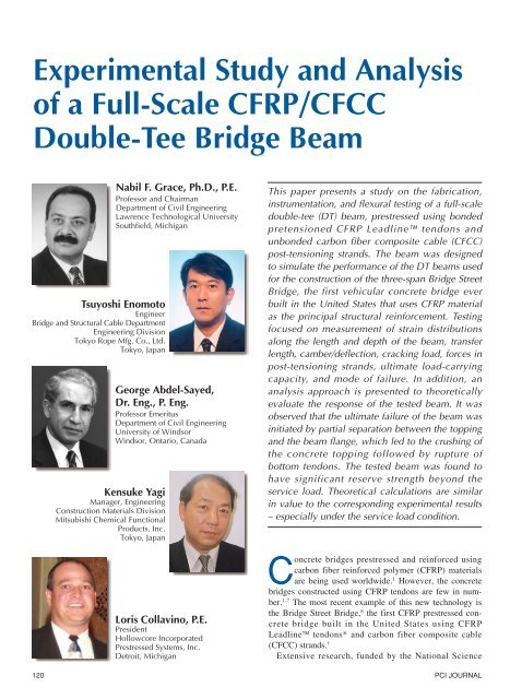
Experimental Study and Analysis of a Full-Scale CFRP/CFCC ...
Experimental Study and Analysis of a Full-Scale CFRP/CFCC ...
Experimental Study and Analysis of a Full-Scale CFRP/CFCC ...
Create successful ePaper yourself
Turn your PDF publications into a flip-book with our unique Google optimized e-Paper software.
Table 1. Material properties <strong>of</strong> <strong>CFRP</strong> tendons/<strong>CFCC</strong> str<strong>and</strong>s.Leadline <strong>CFCC</strong> 1 x 7 <strong>CFCC</strong> 1 x 37Properties (MCC 15 ) (Tokyo Rope 16 ) (Tokyo Rope 16 )Nominal diameter, in. (mm) 0.39 (10) 0.5 (12.5) 1.57 (40)Effective cross-sectional area, sq in. (mm 2 ) 0.111 (71.6) 0.118 (76.0) 1.17 (752.6)Guaranteed tensile strength, ksi (kN/mm 2 ) 328 (2.26) 271 (1.87) 205 (1.41)Specified tensile strength, ksi (kN/mm 2 ) 415 (2.86) 305 (2.10) 271 (1.87)Young’s modulus <strong>of</strong> elasticity, ksi (kN/mm 2 ) 21,320 (147) 19,865 (137) 18,419 (127)Elongation, percent 1.9 1.5 1.5Guaranteed breaking load, kips (kN) 36.4 (162) 31.9 (142) 240.5 (1070)Ultimate breaking load, kips (kN) 46 (204.7) 36 (160) 316.9 (1410)Table 2. Material properties <strong>of</strong> NEFMAC sheets.Modulus <strong>of</strong> elasticity, ksi (GPa) 12,540 (86.5)Ultimate strength, ksi (MPa) 217 (1500)Ultimate strain, percent 1.8Table 3. Material properties <strong>of</strong> precast concrete <strong>and</strong> concrete topping.Properties Precast concrete Concrete toppingModulus <strong>of</strong> elasticity, ksi (GPa) 5320 (36.7) 4580 (31.6)Strength, ksi (MPa) 7.81 (53.8) 5.7 (39.3)cated using s<strong>of</strong>t materials. All Leadlinetendons were pretensionedusing series <strong>of</strong> conventional steelstr<strong>and</strong>s, <strong>CFRP</strong>-tendon anchor systems,couplers, steel str<strong>and</strong> anchor chucks,<strong>and</strong> a hydraulic jack. Fig. 3 shows thepretensioned <strong>CFRP</strong> Leadline tendonsat a roller hold-down point.When the concrete achieved adequatestrength – 45.9 MPa (6.66 ksi) in48 hours – <strong>CFRP</strong> Leadline tendonswere released in the sequence shown inFig. 4. A typical draped tendon withhold-up <strong>and</strong> hold-down arrangementsis also illustrated in Fig. 4. A close-upview <strong>of</strong> pretensioned tendons, <strong>CFCC</strong>non-prestressing str<strong>and</strong>s, <strong>and</strong> flange reinforcementis provided in Fig. 5.Four externally draped post-tensioning<strong>CFCC</strong> str<strong>and</strong>s were installed afterthe release <strong>of</strong> the pretensioning tendons<strong>and</strong> form removal. Fig. 6 revealsthe post-tensioning str<strong>and</strong>s as seenfrom below the beam. Post-tensioninganchorage details at Diaphragm D6are represented in Fig. 7. Each posttensioningstr<strong>and</strong> was tensioned usinga special apparatus (see Fig. 8) usingspecific sequencing.A special bearing system at DiaphragmsD3, D4, <strong>and</strong> D5 was designed<strong>and</strong> constructed to allow the design(anticipated) movement <strong>of</strong> theexternal <strong>CFCC</strong> str<strong>and</strong>s due to trafficloads <strong>and</strong> temperature changes, <strong>and</strong> toaccommodate construction tolerances(see Fig. 6). This bearing system wascritical to provide an almost frictionlessbearing surface between the <strong>CFCC</strong>str<strong>and</strong>s <strong>and</strong> the diaphragm concrete.Fig. 3. Pretensioned <strong>CFRP</strong> Leadline tendons at roller hold-down location.plant, Prestressed Systems Inc., locatedin Windsor, Ontario, Canada.The sequence <strong>of</strong> fabrication is givenbelow:1. Installation <strong>of</strong> the <strong>CFCC</strong> <strong>and</strong><strong>CFRP</strong> mild reinforcement, steel stirrups,<strong>CFRP</strong> prestressing Leadlinetendons, <strong>and</strong> other embedded itemssuch as hold-up <strong>and</strong> hold-down devices,vibrating wire, <strong>and</strong> electrical resistancestrain gauges in the formwork.2. Installation <strong>and</strong> stressing <strong>of</strong> thepretensioned <strong>CFRP</strong> tendons.3. Casting <strong>and</strong> curing <strong>of</strong> concrete.4. Release <strong>of</strong> pretensioned <strong>CFRP</strong>Leadline tendons after concreteachieved desired strength.5. Removal <strong>of</strong> the prestressed beamfrom the form.6. Installation <strong>of</strong> the longitudinal<strong>CFCC</strong> post-tensioning str<strong>and</strong>s <strong>and</strong> applying60 percent <strong>of</strong> the total post-tensioningforce.Except for those in Row 10, allLeadline tendons were draped priorto pretensioning using hold-down <strong>and</strong>hold-up roller devices. These tendonholdingrollers were specially fabri-InstrumentationThe instrumentation installed in thetest beam was selected to achieve a set<strong>of</strong> measurement objectives. Thesemeasurements included the following:• Pretensioned load applied to <strong>CFRP</strong>Leadline tendons.• Transfer length <strong>of</strong> pretensioned<strong>CFRP</strong> Leadline tendons after release.• Beam camber/deflections duringfabrication/construction sequence.• Concrete strain distributions inbeam cross section <strong>and</strong> concrete topping.• Forces in <strong>CFCC</strong> post-tensioningstr<strong>and</strong>s.122 PCI JOURNAL
Measurement <strong>of</strong>Pretensioning ForcesPretensioning forces were measuredusing a load cell installed between thestressing jack at the live end <strong>and</strong> thechuck anchor, <strong>and</strong> these forces wererecorded on a read-out device. A fewload cells were also positioned at thedead end <strong>of</strong> selected tendon lines betweenthe steel str<strong>and</strong> anchor chuck<strong>and</strong> the bulkhead for spot checking<strong>and</strong> verification <strong>of</strong> the readings takenat the live end.In addition to these load cells, theelongation <strong>of</strong> the tendons <strong>and</strong> gaugepressure <strong>of</strong> the hydraulic pump wereused to verify the desired pretensioningforces. Once the jacking force,gauge pressure, <strong>and</strong> elongation hadbeen recorded, the stressing assemblywas transferred to the next tendon; thisprocedure was continued until all 60Leadline tendons were stressed.The total prestressing forces in each<strong>CFRP</strong> tendon in Rows 1 through 5 <strong>and</strong>Rows 6 through 10 were 82.3 <strong>and</strong> 86.7kN (18.5 <strong>and</strong> 19.5 kips), respectively,after seating losses, or about 40 <strong>and</strong> 42percent <strong>of</strong> the ultimate breaking load<strong>of</strong> the Leadline tendons, respectively.Load cells located at the deadend were continuously monitored during<strong>and</strong> after placement <strong>of</strong> the concreteto measure any changes in thepretensioning forces during concreteplacing <strong>and</strong> curing.Measurement <strong>of</strong> Transfer LengthTransfer length <strong>of</strong> the pretensioningtendons was measured using seven vibratingwire strain gauges with an effectivegauge length <strong>of</strong> 152 mm (6.0in.). Gauges were installed along oneweb at both ends <strong>of</strong> the beam duringfabrication. Strain gauges were installedend to end beginning at the end<strong>of</strong> the beam <strong>and</strong> extending over a distance<strong>of</strong> approximately 1065 mm(42.0 in.). All seven gauges at eachbeam end were located at an elevationcoinciding with the centroid <strong>of</strong> thetotal designed pretensioning force, <strong>and</strong>staggered about the mid-width centerline<strong>of</strong> the web.Measurement <strong>of</strong> Early Age CamberA complete history <strong>of</strong> early age deflectionin the test beam was obtainedFig. 4. Release pattern for 60 pretensioned tendons.Fig. 5. Instrumentation <strong>and</strong> <strong>CFRP</strong>/<strong>CFCC</strong> reinforcing cage <strong>of</strong> one web (looking downfrom top).Fig. 6. Externallydraped post-tensioning<strong>CFCC</strong> str<strong>and</strong>s (lookingfrom below DT beam).July-August 2003 123
Fig. 7. Post-tensioning anchorage details at Diaphragm D6.Fig. 8. Posttensioningapparatus for a<strong>CFCC</strong> externallydraped str<strong>and</strong>.using elevation reference points embeddedin the concrete surface. Elevationpoints were located along the topflange <strong>of</strong> the test beam at midspan, attwo quarter-span points, <strong>and</strong> near thebeam ends. Prior to prestressing tendonrelease, elevation measurementswere recorded for each point <strong>and</strong> usedas a reference for all subsequent measurements.After tendon release, measuredchanges in elevation relative tothe initial pre-release values were usedto calculate beam camber due to prestressingat the mid- <strong>and</strong> quarter-spanpoints.Total camber due to pretensioningforce <strong>and</strong> initial post-tensioning forcewas 20.1 mm (0.79 in.). Net camberafter the addition <strong>of</strong> the topping <strong>and</strong>the final stage <strong>of</strong> post-tensioning was14.3 mm (0.56 in.). Note that a totalloss <strong>of</strong> 6.4 mm (0.25 in.) <strong>of</strong> midspancamber occurred due to changes in thesupport location <strong>and</strong> transportation <strong>of</strong>the beam from the fabrication plant tothe testing facility.The elevation <strong>of</strong> each referencepoint was determined using a precisionlevel <strong>and</strong> surveying rod with ahigh-resolution scale. The precisionlevel used for this application requiredan internal micrometer capable <strong>of</strong> resolvingelevation readings to the nearest0.030 mm (0.001 in.). The top surface<strong>of</strong> each embedded reference pointincorporated a machined indentationto match the pointed end <strong>of</strong> the surveyor’srod.Measurement <strong>of</strong> Concrete StrainsEmbedded electrical-resistancestrain gauges were installed for measuringstrain distributions along thedepth <strong>of</strong> cross sections at midspan <strong>and</strong>quarter-spans. A total <strong>of</strong> 30 straingauges were installed in the test beam.Of these 30 gauges, 21 were installedin the precast section at the fabricationplant, while the remaining nine gaugeswere installed in the cast-in-place concretetopping at the testing facility.Fig. 9. NEFMACreinforcing gridplaced over theflange top.Projected steel stirrupMeasurement <strong>of</strong>Post-tensioning ForcesPrior to post-tensioning, all fourpost-tensioning str<strong>and</strong>s were instrumentedwith load cells at one end (seeFig. 8). The load cells were installed124 PCI JOURNAL
etween the lock nut on the str<strong>and</strong> anchor/head<strong>and</strong> the bearing plate embeddedin the transverse DiaphragmD2 near the end <strong>of</strong> the beam (see Fig.2).Post-tensioning was applied to thefour <strong>CFCC</strong> str<strong>and</strong>s in two separatestages (initial <strong>and</strong> final). The initialpost-tensioning (at the precast yard inWindsor, Canada) consisted <strong>of</strong> applying60 percent <strong>of</strong> the total desiredpost-tensioning force [449 kN (101kips)], equal to 32 percent <strong>of</strong> the ultimatebreaking load <strong>of</strong> <strong>CFCC</strong> post-tensioningstr<strong>and</strong>s on the precast DTbeam. Final post-tensioning was appliedat the Construction TechnologyLaboratories, Inc. (CTL), testing facilityin Skokie, Illinois, after casting theconcrete topping. Final post-tensioningconsisted <strong>of</strong> the remaining 40 percent<strong>of</strong> the total post-tensioning force.Each stage <strong>of</strong> post-tensioning wasapplied in two parts. During the firstpart, approximately 50 percent [133.5kN (30.0 kips)] <strong>of</strong> the required forcewas applied by pulling the str<strong>and</strong>sfrom one end as shown in Fig. 8. Aftercompletion <strong>of</strong> the first part, the posttensioningsetup was moved to the oppositeend where the remaining 50 percent<strong>of</strong> the required force was applied.At the precast facility, the initialpost-tensioning was applied with thebeam supported at Diaphragms D2<strong>and</strong> D6 at intermediate transverse locations.The beam remained supportedin this manner until delivered to theCTL test facility. The beam supportconfiguration prevented the development<strong>of</strong> additional tensile strain due todead loads.At CTL, final post-tensioning wasapplied with the beam supported at theEnd Diaphragms D1 <strong>and</strong> D7 after theplacement <strong>of</strong> the concrete topping tosimulate the post-tensioning <strong>of</strong> the actualDT beams used in the BridgeStreet Bridge. The average measuredstr<strong>and</strong> force after the initial post-tensioningwas 268 kN (60.3 kips), whilethe average measured str<strong>and</strong> force immediatelyafter the final post-tensioningwas 449 kN (101 kips).CTL followed stressing proceduressimilar to those <strong>of</strong> the precast plant:the remaining 40 percent <strong>of</strong> the totalpost-tensioning force was appliedprior to the onset <strong>of</strong> structural testingFig. 10. Flexural load testing at the CTL testing facility.(described below). The average measuredforce in the <strong>CFCC</strong> str<strong>and</strong> priorto the test was 443 kN (99.6 kips),which was slightly less than that observedimmediately after the finalpost-tensioning.Casting <strong>of</strong> Concrete ToppingFinally, a 75 mm (3.0 in.) thick concretetopping was cast over the topflange <strong>of</strong> the precast DT beam. Inpreparation for casting, a <strong>CFRP</strong> NEF-MAC grid reinforcement (see Fig. 9)was installed over the top flange <strong>of</strong> thebeam. In addition, the nine remainingembedded concrete strain gauges requiredfor concrete strain distributionmeasurements were installed atmidspan <strong>and</strong> the two quarter-span locations.The NEFMAC reinforcement was(a) Test setup forflexural loading.(b) Supportcondition <strong>of</strong>test beam.supplied in the form <strong>of</strong> grid sheets,each with a transverse dimension <strong>of</strong>2083 mm (82.0 in.). Each grid sheetincorporated longitudinal reinforcementelements spaced at 300 mm (12in.) <strong>and</strong> transverse elements spaced at100 mm (4 in.) intervals. The NEF-MAC reinforcement was supported on25 mm (1.0 in.) high plastic slab bolsters;these were epoxy-anchored tothe top surface <strong>of</strong> the beam flange.Each grid sheet was secured to theslab bolster using plastic ties.TEST SETUPThe flexural loading test setup <strong>and</strong>support condition for the beam areshown in Figs. 10a <strong>and</strong> 10b, respectively.The beam was loaded alongtwo lines to create a 3658 mm (12.0ft) wide constant moment region sym-July-August 2003 125
Output data from instrumentationwere monitored throughout the test<strong>and</strong> recorded at each loading increment.RESULTS AND DISCUSSIONFig. 11. Location <strong>of</strong> four-point loading system, showing location <strong>of</strong> displacementtransducers.Transfer LengthFig. 12 shows the concrete strainplotted against distance from the liveend <strong>of</strong> the beam. The strain valuesrefer to data recorded at various timeintervals (immediately, 5 minutes, 1hour, 26 hours, <strong>and</strong> 43 hours after release,<strong>and</strong> prior to initial post-tensioning).It can be seen from Fig. 12 thatthe transfer length (the distance fromthe beam end at which full effectiveprestress is transferred to the concrete)is approximately 381 mm (15.0 in.),compared to a theoretical value <strong>of</strong> 419mm (16.5 in.) [based on Eq. (4) inReference 11].Thus, experimental <strong>and</strong> calculatedresults for transfer length <strong>of</strong>Leadline tendons are similar invalue. As indicated by the measureddata, concrete strains gradually increasedwith distance from the beamend until strains stabilized or becameuniform (at the location <strong>of</strong> the third vibrating-wirestrain gauge).Fig. 12. Concrete strain versus distance from beam live end.metrical about midspan (see Fig. 11).The loading lines were oriented orthogonallyto the longitudinal centerline<strong>of</strong> the beam. Along each line, loadwas applied at two bearing points thatwere coincident with the beam webs.Roller supports in Fig. 10b were usedat each beam end to allow both longitudinalmovement <strong>and</strong> rotation underthe load.Load was applied using a series <strong>of</strong>hydraulic jacks with load <strong>and</strong> extensioncapability sufficient to induceflexural failure. All loads applied tothe beam during the test were monitoredusing load cells. Beam displacementsat mid- <strong>and</strong> quarter-span locationswere monitored using twodisplacement transducers at each locationattached to the underside <strong>of</strong> thetwo webs.In addition to the applied loads <strong>and</strong>deflections, output from the concretestrain gauges installed for measuringstrain distribution at midspan <strong>and</strong> twoquarter-span sections – <strong>and</strong> from thelongitudinal <strong>CFCC</strong> str<strong>and</strong> load cells –was monitored during the flexural test.Strain Distribution after Posttensioning<strong>and</strong> Service LoadThe distribution <strong>of</strong> concrete strainsalong the depth <strong>of</strong> the cross sections[at mid- <strong>and</strong> two quarter-span (Q-S)locations] after the final post-tensioning<strong>and</strong> due to service load is shown inFigs. 13a <strong>and</strong> 13b, respectively. Fig.13a indicates that after final post-tensioning,the strain at the top surface <strong>of</strong>the concrete topping (at midspan) issmall <strong>and</strong> tensile in nature, whereasthe strain throughout the depth <strong>of</strong>cross section is in the compressionrange.High compressive strain developedat the bottom at each cross section location.The developed compressivestrain levels were desirable to eliminateany potential cracking problemsunder service load/traffic condition.The DT cross section dimensions, theplacement <strong>and</strong> arrangement <strong>of</strong> prestressingtendons, as well as post-ten-126 PCI JOURNAL
(a) After final post-tensioning(b) Due to service loadFig. 13. Strain measurements: (a) Average measured concrete strain along the depth <strong>of</strong> cross section after final post-tensioning;<strong>and</strong> (b) Strain due to service load.(a) At cracking load(b) At ultimate loadFig. 14. Average measured concrete strain: (a) At cracking load; <strong>and</strong> (b) At ultimate load.sioning str<strong>and</strong>s, were selected so thatno cracking would occur under serviceloads.Superposition <strong>of</strong> the concrete strainreadings due to pretensioning <strong>and</strong>post-tensioning shown in Fig. 13a <strong>and</strong>the service load condition in Fig. 13bindicates that the net strain at the bottom<strong>and</strong> top surfaces <strong>of</strong> the beam iscompressive. This strain result is desirablein eliminating any potentialcracking problems in the <strong>CFRP</strong> prestressedconcrete beam under serviceloading.Strain Distribution at Cracking <strong>and</strong>Ultimate LoadsAfter reaching the service loadlevel, incremental loading <strong>of</strong> the DTbeam continued to reach the appliedload corresponding to the development<strong>of</strong> the first concrete crack. To accomplishthis objective, the beam wasloaded in suitably small increments sothat careful observations could bemade <strong>of</strong> the bottom surface for beamstrains within the constant moment region.After application <strong>of</strong> each increment,loading was suspended to allowsufficient time to visually inspect forcracking.The total applied load correspondingto the development <strong>of</strong> the firstcrack was found to be 643.9 kN(144.7 kips). Figs. 14a <strong>and</strong> 14b showthe concrete strain distributions alongthe depth <strong>of</strong> cross sections at mid- <strong>and</strong>quarter-span (Q-S) locations at thecracking <strong>and</strong> ultimate load conditions.Note that the strain readings shown inFig. 14 are only due to the appliedloads <strong>and</strong> do not include the pretensioning<strong>and</strong> post-tensioning effects.Fig. 14 shows that the strain distributionsat the quarter-span sectionsare very close in value. In Fig. 14b,the ultimate strain at the top <strong>of</strong> concretetopping has reached a compressivestrain as high as 0.0025, whereasthe webs are in tension. Note that datafor web strain at the midspan sectionunder the ultimate load condition inFig. 14b are not presented due to failure<strong>of</strong> the corresponding strain gauge.Superposition <strong>of</strong> the concrete strainreadings due to pretensioning <strong>and</strong>post-tensioning <strong>and</strong> the cracking loadconditions shown in Figs. 13a <strong>and</strong> 14aindicates that the net strain at the bottom<strong>of</strong> the beam is close to the strainvalue corresponding to the modulus <strong>of</strong>rupture <strong>of</strong> concrete.July-August 2003 127
Fig. 15. Beam deflection response at midspan under ultimate load.The ultimate load applied during thetest was 2443.0 kN (549.1 kips). Averagemidspan deflections at the service,cracking, <strong>and</strong> ultimate load conditionswere 12.82, 18.67, <strong>and</strong> 342.3 mm(0.505, 0.74, <strong>and</strong> 13.48 in.), while thecorresponding forces in the unbondedpost-tensioning <strong>CFCC</strong> str<strong>and</strong>s were450.0, 453.8, <strong>and</strong> 807.1 kN (101.1,102.0, <strong>and</strong> 181.4 kips), respectively.Fig. 16 indicates that the failure <strong>of</strong>the DT beam occurred in the constantmoment region along one side <strong>of</strong> themidspan Diaphragm D4 <strong>and</strong> that thefailure plane extended across thewidth <strong>of</strong> the beam. The ultimate failure<strong>of</strong> the DT beam was initiated bypartial separation between the bottom<strong>of</strong> the topping <strong>and</strong> top <strong>of</strong> the beamflange, which led to crushing <strong>of</strong> theconcrete topping. This was due to thedifference in the stiffness <strong>and</strong> strength<strong>of</strong> the concrete topping <strong>and</strong> precastconcrete section.After the concrete topping failed, anattempt was made to further increasethe load. As Fig. 15 shows, however,the rupture <strong>of</strong> Leadline tendons ledto the beam collapse without any furtherincrease in the load. The forcelevels in the four <strong>CFCC</strong> post-tensioningstr<strong>and</strong>s (see Fig. 17) nearly doubledduring the test, increasing fromapproximately 443 kN (99.6 kips) atthe onset <strong>of</strong> loading to 807 kN (181.4kips) at the ultimate load, yet none <strong>of</strong>the <strong>CFCC</strong> str<strong>and</strong>s nor their anchorsruptured.Fig. 16. Closeup<strong>of</strong> beam failure.Externalunbonded <strong>CFCC</strong>post-tensioningstr<strong>and</strong>s did notrupture.ULTIMATE BEHAVIOR OFDT BEAMUltimate flexural strength wasreached when the beam was incrementallyloaded to a total load <strong>of</strong> 1303.9kN (293.1 kips) <strong>and</strong> then unloaded(see Fig. 15). This load representsabout 50 percent <strong>of</strong> the actual ultimatestrength. The loading <strong>and</strong> unloadingsequence was necessary to evaluatethe ductility <strong>of</strong> the beam. After the initialloading <strong>and</strong> unloading sequence,the beam was incrementally loaded toinduce flexural failure.ANALYSISAn analysis <strong>of</strong> experimental resultsobtained from the full-scale DT testbeam is presented in this paper. A theoreticalanalysis was also developed topredict the strength <strong>and</strong> failure mode<strong>of</strong> the DT test beam. The strains,stresses, <strong>and</strong> forces in str<strong>and</strong>s, <strong>and</strong> deflection<strong>of</strong> the beam were calculatedfor the service <strong>and</strong> ultimate loadingconditions. 14 Details <strong>of</strong> the theoreticalanalysis <strong>and</strong> calculations are presentedin Appendix A. 15-20CONCLUSIONSBased on the results <strong>of</strong> the test program,the following conclusions canbe drawn:128 PCI JOURNAL
Fig. 17. Force in<strong>CFCC</strong> posttensioningstr<strong>and</strong>s,indicating responseunder ultimate load<strong>and</strong> failure <strong>of</strong> DTbeam.1. The test results <strong>and</strong> constructionexperience gained from this evaluationhave been implemented in the designdocuments for the 12 DT beams requiredfor the construction <strong>of</strong> theBridge Street Bridge.2. The DT beam had significant reservestrength beyond the service load.The ultimate load <strong>and</strong> the crackingload <strong>of</strong> the DT beam were, respectively,approximately 5.3 <strong>and</strong> 1.4times the service load.3. The combined internal <strong>and</strong> externalprestressing forces induced the designedcompressive strain in the crosssection.4. The ultimate failure <strong>of</strong> the DTbeam was initiated by partial separationbetween the topping <strong>and</strong> the beamflange, which led to crushing <strong>of</strong> theconcrete topping followed by rupture<strong>of</strong> the internal prestressing tendons.5. Significant cracking was observedprior to failure. However, none <strong>of</strong> theexternal unbonded <strong>CFCC</strong> post-tensioningstr<strong>and</strong>s nor their anchors ruptured.6. Theoretical values <strong>and</strong> experimentalresults are very close, especiallyunder service load condition.The theoretical nominal moment capacity<strong>of</strong> the DT beam is about 0.9percent lower than the correspondingexperimental value, whereas the predictedforces in the unbonded posttensioningstr<strong>and</strong>s at the service <strong>and</strong>ultimate load conditions are 0.5 <strong>and</strong>6.1 percent lower than correspondingexperimental values.ACKNOWLEDGMENTSThe DT beam for this study wasconstructed by Prestressed SystemsInc. (PSI), Windsor, Ontario, Canada,<strong>and</strong> tested by Construction TechnologyLaboratories, Inc. (CTL), Skokie,Illinois. Hubbell, Roth & Clark(HRC), Consulting Engineers, BloomfieldHills, Michigan, provided the entiredesign, drawing details, <strong>and</strong> constructionadministration services. TheCity <strong>of</strong> Southfield <strong>and</strong> the FederalHighway Administration jointlyfunded the instrumentation <strong>and</strong> testing<strong>of</strong> the DT beam.The National Science Foundation,Division <strong>of</strong> Civil <strong>and</strong> Mechanical Systems,funded the research activities,testing <strong>of</strong> several one-third-scale models(conducted in the Structural TestingCenter at Lawrence TechnologicalUniversity), <strong>and</strong> the analytical evaluation<strong>of</strong> the full-scale testing.Mitsubishi Chemical FunctionalProducts, Inc., Tokyo Rope ManufacturingCo. Ltd., Autocon CompositesInc., Toronto, Canada, SumitomoCorporation <strong>of</strong> America, <strong>and</strong> MitsuiUSA Corporation also supported theongoing research investigation. Thetireless efforts <strong>of</strong> Drs. S. B. Singh <strong>and</strong>T. P. Murphy in these research <strong>and</strong>testing investigations are highly appreciated.The authors also appreciate the technicalcomments <strong>of</strong> Dr. G. Tadros <strong>and</strong>the many constructive comments <strong>of</strong>the PCI JOURNAL reviewers.July-August 2003 129
REFERENCES1. ACI Committee 440, “State-<strong>of</strong>-the-Art Report on Fiber ReinforcedPlastic Reinforcement for Concrete Structures,” ACI440R-96, American Concrete Institute, Farmington Hills, MI,1996, 153 pp.2. Rizkalla, S. H., “A New Generation <strong>of</strong> Civil EngineeringStructures <strong>and</strong> Bridges,” Proceedings <strong>of</strong> the Third InternationalSymposium on Nonmetallic (FRPRC) Reinforcement for ConcreteStructures, Sapporo, Japan, V. 1, October 1997, pp. 113-128.3. Dolan, C. W., “FRP Prestressing in the U.S.A.,” Concrete International,V. 21, No. 10, October 1999, pp. 21-24.4. Tadros, G., “Provisions for Using FRP in the Canadian HighwayBridge Design,” Concrete International, V. 22, No. 7,July 2000, pp. 42-47.5. Fam, A. Z., Rizkalla, S. H., <strong>and</strong> Tadros, G., “Behavior <strong>of</strong><strong>CFRP</strong> Prestressing <strong>and</strong> Shear Reinforcements <strong>of</strong> ConcreteHighway Bridges,” ACI Structural Journal, V. 94, No. 1, January-February1997, pp. 77-86.6. Shehata, E., Abdelrahman, A., Rizkalla, S. H., <strong>and</strong> Tadros, G.,“The New Generation,” Concrete International, V. 20, No. 6,June 1998, pp. 35-38.7. Grace, N. F., <strong>and</strong> Abdel-Sayed, G., “Ductility <strong>of</strong> PrestressedConcrete Bridges Using <strong>CFRP</strong> Str<strong>and</strong>s,” Concrete International,V. 20, No. 6, June 1998, pp. 25-30.8. Grace, N. F., Navarre, F. C., Nacey, R. B., Bonus, W., <strong>and</strong>Collavino, L., “Design-Construction <strong>of</strong> Bridge Street Bridge –First <strong>CFRP</strong> Bridge in the United States,” PCI JOURNAL, V.47, No. 5, September-October 2002, pp. 20-35.9. Grace, N. F., <strong>and</strong> Abdel-Sayed, G., “Behavior <strong>of</strong> ExternallyDraped <strong>CFRP</strong> Tendons in Prestressed Concrete Bridges,” PCIJOURNAL, V. 43, No. 5, September-October 1998, pp. 88-101.10. Grace, N. F., “Response <strong>of</strong> Continuous <strong>CFRP</strong> Prestressed ConcreteBridges Under Static <strong>and</strong> Repeated Loadings,” PCIJOURNAL, V. 45, No. 6, November-December 2000, pp. 84-102.11. Grace, N. F., “Transfer Length <strong>of</strong> <strong>CFRP</strong>/<strong>CFCC</strong> Str<strong>and</strong>s forDouble-T Girders,” PCI JOURNAL, V. 45, No. 5, September-October, 2000, pp. 110-126.12. Grace, N. F., Enomoto, T., <strong>and</strong> Yagi, K., “Behavior <strong>of</strong> <strong>CFCC</strong><strong>and</strong> <strong>CFRP</strong> Leadline Prestressing System in Bridge Construction,”PCI JOURNAL, V. 47, No. 3, May-June 2002, pp. 90-103.13. Grace, N. F., Abdel-Sayed, G., Navarre, F. C., Nacey, R. B.,Bonus, W., <strong>and</strong> Collavino, L., “<strong>Full</strong>-<strong>Scale</strong> Test <strong>of</strong> PrestressedDouble-Tee Beam,” Concrete International, V. 25, No. 4,April 2003, pp. 52-58.14. Grace, N. F., <strong>and</strong> Singh, S. B., “Design Approach for <strong>CFRP</strong>Prestressed Concrete Bridge Beams,” ACI Structural Journal,V. 100, No. 3, May-June 2003, pp. 365-376.15. Mitsubishi Chemical Corporation (MCC), Leadline CarbonFiber Tendons/Bars, Product Manual, 1994.16. Tokyo Rope Mfg. Co. Ltd., Technical Data on <strong>CFCC</strong>, ProductManual, 1993.17. NEFMAC, Technical Data Collection, Autocon CompositesInc., Canada, 1996, pp. 1-10.18. ACI Committee 318, “Building Code Requirements for StructuralConcrete (ACI 318-02) <strong>and</strong> Commentary (318R-02),”American Concrete Institute, Farmington Hills, MI, p. 105.19. Chad, R. B., <strong>and</strong> Dolan, C. W., “Flexural Design <strong>of</strong> PrestressedConcrete Beams Using FRP Tendons,” PCI JOUR-NAL, V. 46, No. 2, March-April 2001, pp. 76-87.20. Naaman, A. E., <strong>and</strong> Alkhairi, F. M., “Stress at Ultimate in UnbondedPost-tensioning Tendons: Part 2 – Proposed Methodology,”ACI Structural Journal, V. 88, No. 6, November-December1991, pp. 683-692.130 PCI JOURNAL
APPENDIX A – ANALYSIS PROCEDUREThe following procedure illustrates the steps for predictingthe behavior <strong>of</strong> the full-scale pretensioned <strong>and</strong> post-tensionedDT test beam. The material properties <strong>of</strong> the tendons,str<strong>and</strong>s, NEFMAC grids, <strong>and</strong> concrete are presented inTable 1. It should be noted that the term “tendon” is used forLeadline TM rods <strong>and</strong> “str<strong>and</strong>” is used for <strong>CFCC</strong> cablesthroughout the paper. It should also be noted that the crosssectionalarea <strong>of</strong> NEFMAC grids has not been included inthe analysis presented below:Step 1 — Calculate required moment capacity:Total dead load <strong>of</strong> beam = 142 kipsDead load /unit length, W d = 142/67 = 2.12 kip/ftDead load moment at midspan:MDWLd=82212 . × 67=8= 1188.8 kip-ftLet W be the total midspan load applied through 4-pointloading system. The distance between the center <strong>of</strong> eachsupport to the nearest load point = 27.5 ftDesign service live load = 104.3 kipsService live load moment at midspan,104. 3 × 27.5M L=2= 1434.13 kip-ftRequired moment capacity <strong>of</strong> the section,M required = 1.4M D + 1.7M L (ACI 318-02)= 4102.34 kip-ftStep 2 — Calculate balanced ratio, ρ b :fc′εcuρb= 085 . β 1(A1)f ε + ε −εwheref c ′ = strength <strong>of</strong> precast concrete = 7.81 ksi (see Table 3)ε fu = specified ultimate strain <strong>of</strong> bonded pretensioningtendons = 0.019 (see Table 1)f fu = specified strength <strong>of</strong> bonded pretensioning tendons= 415 ksi (see Table 1)β 1 = 0.85 – [(7810 – 4000)/1000] × 0.05 = 0.66(ACI 318-02)Based on experimental results, 25 percent loss in the prestressingforce in the bonded tendons is considered. The initialeffective strain in bottom pretensioning tendons, ε pbmi ,can be calculated as follows:19. 5 × 0.75ε pbmi=0. 111 × 21,320= 0.00622fucu fu pbmiBased on experimental observation, the ultimate strain inconcrete, ε cu , is taken as 0.0025. This value <strong>of</strong> strain is veryclose to the value <strong>of</strong> 0.003 recommended by ACI 318-02.The use <strong>of</strong> measured value <strong>of</strong> crushing strain in theoreticalevaluation will amount to an accurate comparison <strong>of</strong> the theoretical<strong>and</strong> experimental values <strong>of</strong> the ultimate load carryingcapacity <strong>of</strong> the DT beam. Substituting the values in Eq.(A1) yields ρ b = 0.0017.Step 3 — Calculate cracking moment, M cr , <strong>and</strong>cracking load, P cr :Modulus <strong>of</strong> rupture <strong>of</strong> concrete,f r = 6.0 f c′= 530 psiVarious sectional properties <strong>of</strong> the DT beam section (seeFig. A1) are presented in Table A1.Total effective pretensioning force,F pre = 1139.3 × 0.75= 854.5 kipsTotal effective post-tensioning force, F post = 397.8 kipsStress at the bottom fiber <strong>of</strong> the section due to pretensioningforce,FpreFpreeb( σ c) b 1=− −(A2)A SpHere, A p <strong>and</strong> S bp are cross-sectional area <strong>and</strong> section modulus(with respect to bottom fiber) <strong>of</strong> precast section, respectively;e b is the eccentricity <strong>of</strong> resultant pretensioning forcewith respect to the centroid <strong>of</strong> the precast section. FromTable A1, A p = 1462 sq in., S bp =11,192 in. 3 , <strong>and</strong> e b = 13 in.Substituting values in Eq. (A2) results in (σ c ) b1 = –1.577 ksi.Since 60 percent <strong>of</strong> the total post-tensioning force wasused to prestress the precast DT concrete section <strong>and</strong> the remaining40 percent <strong>of</strong> the total post-tensioning force was appliedon the composite concrete section (DT beam plus concretetopping), then the stress at the bottom fiber <strong>of</strong> sectiondue to post-tensioning force, (σ c ) b2 , is:( σ c) b 2=06 . × Fpost06 . × Fposteup04 . × Fpost04× . Fpost× euc− −− −ApSbpAcSbc(A3)Here, e up <strong>and</strong> e uc are the eccentricity <strong>of</strong> unbonded posttensioningstr<strong>and</strong>s with respect to the centroids <strong>of</strong> precast<strong>and</strong> composite sections, respectively. From Table A1, values<strong>of</strong> e up <strong>and</strong> e uc are 19.12 <strong>and</strong> 21.67 in., respectively. Substitutingthe values in Eq. (A3),(σ c ) b2 = –0.938 ksiThe cracking moment (M cr ) can be found from the followingexpression:(σ c ) b1 + (σ c ) b2 + M cr /S bc = f r (A4)Here, S bc is the section modulus <strong>of</strong> composite section withbpJuly-August 2003 131
Table A1. Section properties <strong>of</strong> DT beam cross section.Sectional properties Precast section Composite sectionCross-sectional area, sq in. 1462 1673Moment <strong>of</strong> inertia, in. 4 328,489 403,821Distance <strong>of</strong> centroid <strong>of</strong> the section from the bottom fiber <strong>of</strong> the section, in. 29.35 31.90Distance <strong>of</strong> centroid <strong>of</strong> the section from the top fiber <strong>of</strong> the section, in. 18.68 19.08Section modulus corresponding to the bottom fiber <strong>of</strong> section, in. 3 11,192 12,659Section modulus corresponding to the top fiber <strong>of</strong> section, in. 3 17,585 21,165Eccentricity <strong>of</strong> resultant pretensioned force, in. 13 N/AEccentricity <strong>of</strong> unbonded post-tensioning str<strong>and</strong>s, in. 19.12 21.67Note: 1 in. = 25.4 mm; 1 sq in. = 645 mm 2 ; 1 in. 3 = 16387 mm 3 ; 1 in. 4 = 416231 mm 4 .N/A refers to a non-applicable value for calculating stresses <strong>and</strong>/or moment due to pretensioning forces because pretensioning forces were not applied to the composite section.respect to extreme tension fiber <strong>and</strong> is equal to 12,659 in. 3(see Table A1). Substituting the values in Eq. (A4),M cr = 3212.2 kip-ftThus, cracking load,Pcr( Mcr− MD)× 2=27.5= 147.2 kips > service load (104.3 kips)Percent difference between the theoretical <strong>and</strong> experimentalcracking loads:( 147. 2 − 144. 7)=× 100144.7= 17 . percentStep 4 — Compute flexural moment capacity:Ultimate bond reduction coefficient for externalstr<strong>and</strong>s,Ω u= 54 . (A5)LuduwhereL u = horizontal distance between anchorages <strong>of</strong> unbondedpost-tensioning tendons = 51.4 ftd u = distance at midspan <strong>of</strong> external post-tensioningstr<strong>and</strong>s from the extreme compression fiber =40.75 in.Substituting the values in Eq. (A5), we get Ω u = 0.36.Distance <strong>of</strong> the centroid <strong>of</strong> bottom bonded pretensioningtendons from the extreme compression fiber, d m = 47 in.Flange width, b = 83.46 in.Total effective pretensioning force, ∑F pi = 854.5 kipsTotal effective post-tensioning force, F pui = 397.8 kips* Equivalent tendon/str<strong>and</strong> means a tendon/str<strong>and</strong> located at centroid <strong>of</strong>tendons/str<strong>and</strong>s <strong>and</strong> having cross-sectional area equal to the total cross-sectionalarea <strong>of</strong> corresponding tendons/str<strong>and</strong>s.It should be noted that the actual reinforcement ratio <strong>of</strong> thesection is defined as the ratio <strong>of</strong> total weighted area <strong>of</strong> the tendons<strong>and</strong>/or str<strong>and</strong>s in the section to the effective concretearea. Here, weighting factor is defined as the ratio <strong>of</strong> the stressin a particular equivalent * tendon/str<strong>and</strong> to the specifiedstrength <strong>of</strong> bonded pretensioning tendons. The expression forthe reinforcement ratio is based on equilibrium <strong>of</strong> forces inconcrete <strong>and</strong> tendons <strong>and</strong> the strain compatibility conditions(see Fig. A1).Flexural stress in the equivalent bonded prestressing tendonat balanced condition, f pbb = 188.7 ksiStress in the equivalent non-prestressing str<strong>and</strong> <strong>of</strong> webs atbalanced condition, f pnbb = 152.4 ksiStress in the equivalent unbonded str<strong>and</strong> at balanced condition,f pub = 72.2 ksiStress in the equivalent non-prestressing tendons <strong>of</strong> flangeat balanced condition, f pnf = 39.94 ksiTotal cross-sectional area <strong>of</strong> bonded prestressing tendons,A pb = 6.66 sq in.Total cross-sectional area <strong>of</strong> non-prestressing str<strong>and</strong>s in thewebs, A pn = 3.304 sq in.Total cross-sectional area <strong>of</strong> unbonded prestressing str<strong>and</strong>s,A fu = 4.68 sq in.Total cross-sectional area <strong>of</strong> non-prestressing tendons in theflange, A pnf = 2.109 sq in.Reinforcement ratio,ρ =m∑ F + f A + f A + F + f A − f Aj = 1pi pbb pb=854. 5+ 188. 7× 6. 66 + 152. 4× 3. 304+ 397. 8+ 72. 2× 4. 68− 39. 94×2.10983.46× 47×415= 0.002 > 0.0017 (ρ b )pnbb pn pui pub fu pnfb pnfb × d × fmfu(A6)Since the section is over-reinforced, failure <strong>of</strong> the beam willoccur due to crushing <strong>of</strong> the concrete topping. The steps tocalculate the moment capacity <strong>of</strong> the DT beam are givenbelow:132 PCI JOURNAL
Fig. A1. Strain <strong>and</strong> stress distributions for DT beam at ultimate loading indicating compressive <strong>and</strong> tensile forces.a. Compute strain in tendons/str<strong>and</strong>s:The strains in tendons/str<strong>and</strong>s can be calculated from thestrain distribution as shown in Fig. A1. The ultimate failure<strong>of</strong> the DT beam was initiated by partial separation betweenthe topping <strong>and</strong> the beam flange, which led to crushing <strong>of</strong>the concrete at the strain level <strong>of</strong> 0.0025. Thus, strain in theconcrete at the extreme compression fiber, ε cu = 0.0025.Let c = depth to the neutral axis from the extreme compressionfiberStrain in bonded prestressing tendons,εpbj0. 0025× ( dj−c)= + εpbji(for j = 1, m) (A7)cStrain in unbonded post-tensioning str<strong>and</strong>s,uε pu= Ωu+ 0.0046 (A8)Strain in non-prestressing str<strong>and</strong>s,ε pnj0. 0025× ( d −c)c0. 0025× ( hj−c)= (A9)cStrain in non-prestressing tendons at flange top,0. 0025× ( c−d)ctε pnt= (A10)Strain in non-prestressing tendons at flange bottom,0. 0025× ( c−d)cbε pnb= (A11)In Eq. (A7), e pbji equals 0.0059 (for j = 1, 5) <strong>and</strong> 0.0062(for j = 6 to 10); d j (j =1 to 10) is the depth <strong>of</strong> an individuallayer, j, <strong>of</strong> the bonded pretensioning tendons from the extremecompression fiber. Here, d 1 , d 2 , d 3 , d 4 , d 5 , d 6 , d 7 , d 8 ,d 9 , <strong>and</strong> d 10 are 21.8, 24.6, 27.4, 30.2, 33.0, 35.8, 38.6, 41.4,44.2, <strong>and</strong> 47.0 in., respectively; d u is the depth <strong>of</strong> unbondedpost-tensioning tendons from the extreme compression fiber<strong>and</strong> is equal to 40.75 in.In Eq. (A9), h j (j = 1 to 6) is the depth <strong>of</strong> an individuallayer, j, <strong>of</strong> the non-prestressing tendons provided in webs.Here, h 1 , h 2 , h 3 , h 4 , h 5 , <strong>and</strong> h 6 are 8.8, 16.4, 23.5, 31.8, 40.1,<strong>and</strong> 48.6 in., respectively; d t [see Eq. (A10)] <strong>and</strong> d b [see Eq.(A11)] are the depth <strong>of</strong> the top <strong>and</strong> bottom layers <strong>of</strong> non-prestressingtendons provided in the flange, respectively. Here,d t <strong>and</strong> d b are 4.5 <strong>and</strong> 6.9 in., respectively.b. Compute resultant forces in tendons/str<strong>and</strong>s <strong>and</strong>concrete:Total cross-sectional area <strong>of</strong> bonded prestressing tendonsin each row, A fb = 0.666 sq in.Total cross-sectional area <strong>of</strong> non-prestressing str<strong>and</strong>s ineach row, A fn = 0.472 sq in. for Rows 1 to 5 <strong>and</strong> A fn = 0.944sq in. for Row 6.Total cross-sectional area <strong>of</strong> non-prestressing tendons atflange top, A fnt = 1.11 sq in.Total cross-sectional area <strong>of</strong> non-prestressing tendons atflange bottom, A fnb = 0.999 sq in.Using the stress-strain <strong>and</strong> force-stress relationships (i.e.,stress = strain × modulus <strong>of</strong> elasticity; <strong>and</strong> force = stress ×cross-sectional area <strong>of</strong> tendons <strong>of</strong> each layer), the resultantforces in each layer <strong>of</strong> prestressing <strong>and</strong> non-prestressing tendonscan be determined by the following expressions:Resultant force in pretensioning tendons,FFpbjpbj⎡35.( 5 dj− c)⎤= ⎢+ 83. 78 j⎣ c⎥ kips for = 1 to 5 (A12a)⎦⎡35.( 5 dj− c)⎤= ⎢+ 88. 03 j⎣ c⎥ kips for = 6 to 10 (A12b)⎦Resultant force in unbonded post-tensioning str<strong>and</strong>s,Fpu =⎡77. 6 ( 40. 75 − c)⎣⎢ c+ 396. 54⎤kips (A13)⎦⎥July-August 2003 133
Table A2. Stresses in tendons <strong>of</strong> different layers at ultimate load condition <strong>of</strong> DT beam.Stress (ksi)Bonded Non-prestressing Unbonded Non-prestressing Non-prestressingpretensioning tendons located post-tensioning tendons located tendons located atLayer number tendons in webs tendons at flange top flange bottom1 205.6 0.40 145.5 25.8 11.22 222.7 43.63 239.8 84.04 256.9 131.25 274.0 178.56 297.5 226.8 N/A N/A N/A7 314.58 331.6N/A9 348.710 365.8Note: 1 ksi = 6.895 MPa.Resultant force in non-prestressing str<strong>and</strong>s,23. 45( hj− c)=c46.( 9 hj− c)=cResultant force in non-prestressing tendons at flange top,Resultant force in non-prestressing tendons at flange bottom,FFpnb =Compressive force in concrete = C t + C f= 0.85f ′ c (E ct /E c )bh t + 0.85f ′ c b(0.66c – 2.95)= [1405.62 + 554.05 (0.66c – 2.95)] kips (A17)c. Compute the neutral axis depth c:From the equation <strong>of</strong> equilibrium,10pnt=⎡53. 3 ( c − 6. 9)⎤⎣⎢ c ⎦⎥∑ F + ∑ F + F = C(A18)pbjj = 1 j = 159. 2( c − 4. 5)cpnj35.5 23.45( 344 − 10 c)+ 859 . 05 + ( 217 . 8 − 7 c)+cc77.6( 40 . 75 − c) + 396 . 54c= 1405. 62 + 554. 05( 0. 66c− 2. 95)+59. 2( c − 4. 5) 53. 3( c − 69 . )+ccSolving for c gives c = 8.73 in.6kips for j = 1 to 5 (A14a)kips for j = 6 (A14b)pukipskips(A15)(A16)d. Compute stresses in tendons/str<strong>and</strong>s:The value <strong>of</strong> strain in tendons/str<strong>and</strong>s can be computedusing Eqs. (A7) through (A11), <strong>and</strong> then using the stressstrainrelationships, stresses in tendons/str<strong>and</strong>s <strong>of</strong> differentlayers can be calculated.For example, stress in the tenth layer <strong>of</strong> bonded pretensioningtendons−=⎡0. 0025 ( 47 c)+ 0. 0062⎤⎣⎢⎦⎥ × 21,320c= 365.8 ksi < 415 ksi (OK)The calculated values <strong>of</strong> the stress in tendons <strong>of</strong> differentlayers are presented in Table A2.e. Compute the resultant force in tendons <strong>and</strong> concrete:Resultant forces in tendons <strong>of</strong> different layers can be calculatedby multiplying the corresponding tendons stress <strong>and</strong>equivalent cross-sectional area <strong>of</strong> tendons <strong>of</strong> a particularlayer. For example, resultant force in pretensioning tendons<strong>of</strong> 10th layer is given by:F pb10 = 365.8 × 0.666= 243.6 kipsThe calculated resultant forces in tendons <strong>of</strong> different layersare presented in Table A3.From Eq. (A17), resultant force in concrete = C t + C f =2963.5 kipsTotal compressive force,C = C t + C f + F pnt + F pnb= 2963.5 + 28.6 + 11.2= 3003.2 kipsTotal resultant tension force,F = ∑ F + ∑ F + FR106pbjj = 1 j = 1pnj= 3004. 3 kips ≅ C (OK)pu134 PCI JOURNAL
Table A3. Resultant forces in tendons <strong>of</strong> different layers at ultimate load condition <strong>of</strong> DT beam.Force (kips)Bonded Non-prestressing Unbonded Non-prestressing Non-prestressingpretensioning tendons located post-tensioning tendons located tendons located atLayer number tendons in webs tendons at flange top flange bottom1 136.9 0.2 680.9 28.6 11.22 148.3 20.63 159.7 39.64 171.1 61.95 182.5 84.36 198.1 214.1 N/A N/A N/A7 209.58 220.8N/A9 232.210 243.6Note: 1 kip = 4.44 kN.f. Compute the ultimate moment capacity:Location <strong>of</strong> the center <strong>of</strong> gravity <strong>of</strong> the resultant tension forcemeasured from the extreme compression fiber, d = 37.61 in.Depth <strong>of</strong> Whitney’s equivalent stress block,a = β 1 c= 0.66 × 8.73= 5.76 in.Distance <strong>of</strong> the center <strong>of</strong> gravity <strong>of</strong> resultant compressionforce from the extreme compression fiber,d =295 .× + ×⎛ 281 .1405.6 1557. 9 2.95 +⎞2⎝ 2 ⎠ + 28. 3 × 4. 5 + 10. 6 × 69 .3003.2= 302 . in.Thus, nominal moment capacity,M n = F R (d – _ d)= 3004.3 × (37.61 – 3.02)= 8659.9 kip-ftDesign moment capacity,M u = 0.85 × 8659.9= 8210.9 kip-ft > 4102.34 kip-ft (M required ) (OK)g. Compare the theoretical <strong>and</strong> experimental values <strong>of</strong>moment capacity <strong>and</strong> post-tensioning tendon force:<strong>Experimental</strong> value <strong>of</strong> the moment capacity <strong>of</strong> DT beam =[(549 × 227.5)/2] + 1188.8 = 8739.0 kip-ftTheoretical nominal moment capacity <strong>of</strong> DT beam = 8659.9kip-ftPercent difference in experimental <strong>and</strong> theoretical momentcapacities,( 8739. 0 − 8659. 9)=× 1008739.0= 09 . percent<strong>Experimental</strong> value <strong>of</strong> post-tensioning force in eachpost-tensioning str<strong>and</strong> = 181.3 kipsTheoretical value <strong>of</strong> post-tensioning force in each tendon= 680.9/4 = 170.2 kipsPercent difference in experimental <strong>and</strong> theoretical values<strong>of</strong> post-tensioning forceh. Compute stresses due to service loads:Moment due to service loads, M = 1188.8 + 1434.13 =2622.93 kip-ft < 3203.9 kip-ft (cracking moment)Since moment due to service loads is less than thecracking moment, the section will remain uncracked at theservice load. The maximum stresses can be calculated asfollows:Maximum compressive stress in concrete at the extremecompression fiber,fct( 181. 3 − 170. 2)=× 100181.3= 61 . percentFpreFpreeb06 . × Fpost06 . × F= − + −ApStpApStp04 . × Fpost04 . × Fpost× e−ASSubstituting the values <strong>of</strong> sectional properties (seeTable A1) <strong>and</strong> other parametric values in Eq. (A19), weget f ct = 1.28 ksi < 4.69 ksi (0.6f c ′) (OK)Maximum concrete stress due to applied load1434.13 × 12=21,165= 081 . ksictcpostuceupM+Stc+(A19)July-August 2003 135
<strong>Experimental</strong> value <strong>of</strong> concrete stress = 1.0 ksiPercent difference in theoretical <strong>and</strong> experimentalvalues <strong>of</strong> concrete stressThis difference in analytical <strong>and</strong> experimentalstrain in concrete topping may be attributed to thechange in the strain condition because <strong>of</strong> the changing<strong>of</strong> the support condition <strong>of</strong> the beam during variousconstruction stages <strong>and</strong> due to different properties<strong>of</strong> the concrete topping <strong>and</strong> precast concrete.Stress in bottom prestressing tendons,f10 . − 081 .= × 10010 .= 19 percentEf M( d10− ytc)= E ε +EcIc= 21,320 × 0.0062 +pb10 f pb10i2622. 93 × 12 × ( 47. 0 −19. 08)4.0 ×40,3821= 132. 19 + 8.70= 140.89 ksi < 415 ksi (OK)Stress in bottom prestressing tendons due to appliedload1434. 13 × 12 × ( 47 −19. 08)= 40 . ×40,3821= 47 .6 ksi ≅ 4.73 ksi (experimental value)Stress in post-tensioning str<strong>and</strong>s,Efp ( M − MD)efpu = Efpεucpui+ΩEcIc= 18, 419 × 0.0046 +( 2622. 93 − 1188. 8) × 12 × 21.67 2346 . ××403,8213= 86.86 ksi < 271 ksi (OK)Force in a <strong>CFCC</strong> str<strong>and</strong> at service load = 86.86 ×1.17 = 101.63 kips<strong>Experimental</strong> value <strong>of</strong> post-tensioning force =101.12 kipsPercent difference in theoretical <strong>and</strong> experimentalvalues <strong>of</strong> post-tensioning force at service load101. 63 − 101.12=× 100101.12= 05 . percent(A20)i. Compute maximum deflection under serviceload (no cracking occurs under service load):M L = M – M D= 1434.13 kip-ftDistance between the support <strong>and</strong> nearest loadpoint, L 1 = 27.5 ftLongitudinal distance between load points, L 2 = 12 ftDeflection due to applied load,MLL ⎛ L ⎞ Lδ a= + ⎜ ⎟EcIc⎝ L ⎠+ ⎛ 22 ⎡⎝ ⎜⎞ ⎤182 2⎢ 40 .⎟ ⎥(A21)8L⎣⎢31 1 ⎠⎦⎥2× × × ⎡=+⎛ ⎞× ×⎝ ⎠ + ⎛ 21434. 13 12 ( 27. 5 12)8 12 12 ⎞ ⎤⎢ 40 .⎣⎝ ⎠ ⎥8 5320 40,3821 3 27. 5 27.5 ⎦= 0.502 in. ↓ ≅ 0.505 in. (experimental value)It should be noted that the precast DT beam was supported at DiaphragmsD2 <strong>and</strong> D6 prior to initial post-tensioning. The center-tocenterdistance between Diaphragms D1 <strong>and</strong> D2, d 12 , was 7.8 ft.Hence, midspan deflection <strong>of</strong> DT beam due to dead load is given byδdd=144 ⎡EIc p ⎣⎢δ =43WDL WDL L−⎛− d⎞12L384 12 ⎝ 2144 ⎡212 . × 67 212 . × 67−⎛⎢5320×328,489 ⎣ 384 12 ⎝= 001 . in. ↓Assuming that the loss <strong>of</strong> pretensioning forces up to the instant<strong>of</strong> initial post-tensioning be negligible,Effective pretensioning force = 1139.3 kipsDeflection due to pretensioning force at the instant <strong>of</strong> initial posttensioning1139. 3 × 13. 0 × ( 67 × 12)=8 × 5320 × 328,489= 069 . in. ↑Center-to-center distance between Diaphragms D2 <strong>and</strong> D6 =51.4 ftDeflection due initial post-tensioning06 . × 3978 . × 1912 . × ( 514 . × 12)=8 × 5320 × 32,8489= 012 . in. ↑Total deflection <strong>of</strong> the precast DT beam after the initial post-tensioning= 069 . + 012 . −001.= 080 . in. ↑<strong>Experimental</strong> value <strong>of</strong> deflection due to pretensioning <strong>and</strong> initialpost-tensioning = 0.79 in. ↑Percent difference in theoretical <strong>and</strong> experimental values <strong>of</strong> deflectionafter initial post-tensioning080 . − 079 .=079 .= 13 . percent⎠ + − ⎤5081. 85 79603.8in.⎦⎥4 326722−⎞⎠ + × − ⎤78 . 5081. 85 67 79603.8⎥⎦136 PCI JOURNAL
Measured loss in the deflection due to transportation <strong>and</strong>support condition change = 0.25 in. ↓Net deflection due to prestressing prior to final post-tensioning= 0.80 – 0.25= 055 . in. ↑Increase in deflection due to final post-tensioning04 . × 3978 . × 2167 . × ( 514 . × 12)=8 × 5320 × 40,3821= 008 . in. ↑Weight <strong>of</strong> the concrete topping150 × 83. 46 × 2.95=212 × 1000= 026 . kip / ft2Deflection due to concrete topping45 026 . × ( 67×12)=384 12 × 5320 × 403,821= 005 . in. ↓Net deflection at the time <strong>of</strong> final post-tensioning= 055 . + 008 . −005.= 058 . in. ↑<strong>Experimental</strong> value <strong>of</strong> the net deflection after final posttensioning= 0.56 in. ↑Percent difference in theoretical <strong>and</strong> experimental values<strong>of</strong> deflection after final post-tensioning058 . − 056 .=× 100056 .= 36 . percentAPPENDIX B — NOTATIONaA cA pA fbA fnA fntA fnbA fuA pbA pnA pnfbcCC t= depth <strong>of</strong> equivalent rectangular compressionblock, in.= cross-sectional area <strong>of</strong> composite DT beam, sqin.= cross-sectional area <strong>of</strong> precast DT beam, sq in.= cross-sectional area <strong>of</strong> bottom bonded prestressingtendons in each row, sq in.= cross-sectional area <strong>of</strong> non-prestressing tendonsin each row, sq in.= cross-sectional area <strong>of</strong> non-prestressing tendonsat flange top, sq in.= cross-sectional area <strong>of</strong> non-prestressing tendonsat flange bottom, sq in.= total cross-sectional area <strong>of</strong> unbonded post-tensioningtendons, sq in.= total cross-sectional area <strong>of</strong> bonded prestressingtendons, sq in.= total cross-sectional area <strong>of</strong> non-prestressing tendonsin the webs, sq in.= total cross-sectional area <strong>of</strong> non-prestressing tendonsin the flange, sq in.= width <strong>of</strong> compression face <strong>of</strong> member, in.= depth to the neutral axis from the extreme compressionfiber, in.= resultant compressive force, kips= resultant compression force in concrete topping,kipsC f = resultant compression force in flange <strong>of</strong> precastDT beam, kipsc.g.c = axis passing through the centroid <strong>of</strong> concretecross section <strong>of</strong> the DT beamc.g.p = axis passing through the center <strong>of</strong> gravity <strong>of</strong> theresultant pretensioned forced 12 = center-to-center distance between DiaphragmsD1 <strong>and</strong> D2, ftd = distance to center <strong>of</strong> gravity <strong>of</strong> the resultant tensionforce from the extreme compression fiber,in._dd jd md bd td u= distance to center <strong>of</strong> gravity <strong>of</strong> the resultant compressionforce from the extreme compressionfiber, in.= distance to centroid <strong>of</strong> bonded prestressing tendons<strong>of</strong> an individual row from the extreme compressionfiber, in.= distance to centroid <strong>of</strong> bottom bonded prestressingtendons (mth row) from the extreme compressionfiber, in.= distance to centroid <strong>of</strong> non-prestressing tendonsat flange bottom from the extreme compressionfiber, in.= distance to centroid <strong>of</strong> non-prestressing tendonsat flange top from the extreme compressionfiber, in.= distance to centroid <strong>of</strong> unbonded post-tensioningJuly-August 2003 137
e be upe ucE cE ctE fE fnE fpf cf ctf ′ cf fuf funf fupf pbbf pbjf pbmf pbmif pnbf pnbbf pnfbf pnjf pnkf pntf puf rF piF preF postF pbjF pbmtendons from the extreme compression fiber, in.= eccentricity <strong>of</strong> resultant pretensioning force fromthe centroid <strong>of</strong> the precast concrete cross section,in.= eccentricity <strong>of</strong> unbonded post-tensioning tendonsfrom centroid <strong>of</strong> the precast concrete cross section,in.= eccentricity <strong>of</strong> unbonded post-tensioning tendonsfrom the centroid <strong>of</strong> composite section= modulus <strong>of</strong> elasticity <strong>of</strong> precast concrete, ksi= modulus <strong>of</strong> elasticity <strong>of</strong> concrete topping, ksi= modulus <strong>of</strong> elasticity <strong>of</strong> bonded tendon, ksi= modulus <strong>of</strong> elasticity <strong>of</strong> non-prestressing tendonsin webs, ksi= modulus <strong>of</strong> elasticity <strong>of</strong> unbonded tendon, ksi= stress in the concrete at extreme compressionfiber in very under-reinforced beam, ksi= stress in the concrete at extreme compressionfiber in over-reinforced beam, ksi= specified compressive strength <strong>of</strong> precast concrete,ksi= specified ultimate tensile strength <strong>of</strong> bonded prestressingtendons, ksi= specified ultimate tensile strength <strong>of</strong> non-prestressingtendons in webs, ksi= specified ultimate tensile strength <strong>of</strong> unbondedpost-tensioning tendons, ksi= flexural stress in the equivalent bonded prestressingtendons at balanced condition, ksi= total stress in bonded prestressing tendons <strong>of</strong> anindividual row, ksi= total stress in bottom prestressing tendons (mthrow), ksi= initial effective prestress in bottom bonded prestressingtendons (mth row), ksi= total stress in non-prestressing tendons at flangebottom, ksi= stress in the equivalent non-prestressing tendonin the webs, ksi= stress in the equivalent non-prestressing tendonin the flange, ksi= total stress in non-prestressing tendons <strong>of</strong> an individualrow in webs, ksi= total stress in non-prestressing tendons <strong>of</strong> bottomrow (kth row), ksi= total stress in non-prestressing tendons at flangetop, ksi= total stress in unbonded post-tensioning tendons,ksi= modulus <strong>of</strong> rupture <strong>of</strong> concrete, psi= initial effective prestress in bonded pretensioningtendons, kips= resultant effective pretensioning force in bondedtendons, kips= resultant effective post-tensioning force in unbondedtendons, kips= resultant tensile force in bonded prestressing tendons<strong>of</strong> an individual row, kips= resultant tensile force in bonded bottom (mthrow) prestressing tendons, kipsF pnb = resultant compression force in non-prestressingtendons at flange bottom, kipsF pnj = resultant tensile force in non-prestressing tendons<strong>of</strong> individual row in webs, kipsF pnk = resultant tensile force in non-prestressing tendons<strong>of</strong> bottom row (kth row) in webs, kipsF pnt = resultant compression force in non-prestressingtendons at flange top, kipsF pu = resultant tensile force in unbonded post-tensioningtendons, kipsF pui = total initial effective post-tensioning force, kipsF R = resultant <strong>of</strong> the tensile forces in bonded <strong>and</strong> unbondedtendons, kipsh f = flange thickness <strong>of</strong> DT beam, in.h j = distance <strong>of</strong> centroid <strong>of</strong> non-prestressing tendons<strong>of</strong> an individual row in webs, in.h k = distance <strong>of</strong> centroid <strong>of</strong> bottom non-prestressingtendons (kth row), in.h t = thickness <strong>of</strong> concrete topping, in.I c = moment <strong>of</strong> inertia <strong>of</strong> composite concrete crosssection, in. 4I p = moment <strong>of</strong> inertia <strong>of</strong> precast concrete cross section,in. 4k = number <strong>of</strong> rows <strong>of</strong> non-prestressing tendons inwebs <strong>of</strong> DT beamL = effective span <strong>of</strong> the beam, ftL u = horizontal distance between the ends <strong>of</strong> unbondedpost-tensioning str<strong>and</strong>, ftm = number <strong>of</strong> rows <strong>of</strong> bonded tendonsM = applied maximum moment due to service loads,kip-ftM cr = cracking moment capacity <strong>of</strong> section, kip-ftM u = design moment capacity <strong>of</strong> section, kip-ftM D = maximum bending moment due to dead load,kip-ftM L = maximum bending moment due to live load, kipftM n = nominal moment capacity <strong>of</strong> section, kip-ftM required = required moment capacity <strong>of</strong> the section, kip-ftp = number <strong>of</strong> materials used for tension reinforcementP cr = midspan load causing cracking <strong>of</strong> DT beam, kipsS bc = section modulus corresponding to the bottom extremefiber <strong>of</strong> composite section, in. 3S bp = section modulus corresponding to the bottom extremefiber <strong>of</strong> precast section, in. 3S tp = section modulus corresponding to the top extremefiber <strong>of</strong> precast section, in. 3S tc = section modulus corresponding to the top extremefiber <strong>of</strong> composite section, in. 3W = total midspan load, kipsW_d = self-weight <strong>of</strong> beam per unit length, kip/fty = distance <strong>of</strong> centroid <strong>of</strong> tension reinforcementfrom the extreme compression fiber, in.y bc = distance <strong>of</strong> centroid <strong>of</strong> composite section fromthe bottom fiber, in.y bp = distance <strong>of</strong> centroid <strong>of</strong> precast section from thebottom fiber, in.138 PCI JOURNAL
y tc = distance <strong>of</strong> centroid <strong>of</strong> composite cross sectionfrom the top fiber, in.β 1 = factor defined as the ratio <strong>of</strong> the equivalent rectangularstress block depth to the distance fromthe extreme compression fiber to the neutral axisε cu = ultimate compression strain in concrete (0.0025)ε fbj = flexural strain in the bonded prestressing tendons<strong>of</strong> an individual rowε fbm = flexural strain in the bonded prestressing tendons<strong>of</strong> bottom row (mth row)ε fu = ultimate tensile strain capacity <strong>of</strong> bonded prestressingtendonsε fun = ultimate tensile strain capacity <strong>of</strong> non-prestressingtendons in websε fup = ultimate tensile strain capacity <strong>of</strong> unbonded tendonsε pbj = total strain in bonded prestressing tendons <strong>of</strong> anindividual rowε pbji = initial strain in bonded prestressing tendons <strong>of</strong> anindividual rowε pbm = total strain in bonded prestressing tendons <strong>of</strong> mthrowε pbmi = initial strain in bonded prestressing tendons <strong>of</strong>mth rowε pnb = total strain in non-prestressing tendons at flangebottomε pnj = total strain in non-prestressing tendons <strong>of</strong> an individualrow in websε pnkε pntε puε pui∆ε puα= total strain in non-prestressing tendons <strong>of</strong> bottomrow (kth row)= total strain in non-prestressing tendons at flangetop= total strain in unbonded post-tensioning tendons= initial strain in unbonded post-tensioning tendons= flexural strain in unbonded post-tensioning tendons= ratio <strong>of</strong> the effective post-tensioning force appliedto the precast DT beam to the total effectivepost-tensioning force(σ c ) b1 = stress at extreme tension fiber due to pretensioningforce, ksi(σ c ) b2 = stress at extreme tension fiber due to post-tensioningforce, ksiρρ bΩ uδδ aδ dδ p= tensile reinforcement ratio= balanced ratio= bond reduction coefficient at ultimate= maximum midspan deflection <strong>of</strong> the beam underservice loads, in.= maximum midspan deflection <strong>of</strong> the beam due toapplied load, in.= maximum midspan deflection <strong>of</strong> the beam due todead load, in.= maximum midspan deflection <strong>of</strong> the beam due toprestressing forces, in.July-August 2003 139


