SMARTESTER ANUAL - Supco
SMARTESTER ANUAL - Supco
SMARTESTER ANUAL - Supco

You also want an ePaper? Increase the reach of your titles
YUMPU automatically turns print PDFs into web optimized ePapers that Google loves.
<strong>SMARTESTER</strong> M<strong>ANUAL</strong>For Use With2 nd Generation Smart ValveValves with an LED1 Stage/2 Stage Valves24 & 120-Volt IgnitersSV9510, SV9520, SV9610, SV9620, SV9540, SV9640, SV9440The Professional’s ChoiceREV. 2PO Box 21 • 2230 Landmark Place • Allenwood, NJ USA732-223-6644 • Fax 732-223-1617www.supco.com • info@supco.com19204Sealed Unit Parts Co., inc.PO Box 21 • 2230 Landmark Place • Allenwood, NJ USA732-223-6644 • Fax 732-223-1617www.supco.com • info@supco.com
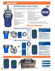
IntroductionThe SmarTester is a non-intrusive hand-held diagnostic tool fortroubleshooting electronic ignition systems of gas-fired heatingappliances, water heaters and more. It does not operate, but monitorselectronic signals of various appliance components and power suppliesthrough its cables.The SmarTester works along side the internal test circuitry of theequipment and is capable of quickly diagnosing a number of problemswithin multiple circuits of the equipment control system simultaneously.Hard to find intermittent problems are easily solved.The service technician can then make a “Smart” decision to repair theequipment.IMPORTANT!!!!• The SmarTester is intended to be used by a qualified service technicianor electrician.• Always use proper techniques while testing to avoid damaging thecontrol terminals, connectors, or interface cable.• In cases where wires are to be removed for testing, always label wiresprior to disconnection. Wiring errors can cause improper anddangerous operation.• Always refer to the equipment manual provided by the manufacturerprior to servicing any equipment.• Always make sure all power to the system being tested is off; plug theinterface cable into the SmarTester, then make the connections on thecontrol.• Make sure all wiring connections are secured correctly and are snug.• A wet control could cause bodily harm; never test controls that havebeen wet. Replace them.• A wet or damaged controller may create erroneous information.• WARNING!! Using the interface cable on a control not listed in thismanual could damage the equipment or SmarTester, or could pose ashock hazard. USE ONLY WITH APPROVEDCONTROLS!!• Improper use of this unit could cause death, serious injury, or propertydamage.114
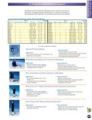
ApplicationsInspections and Installations• Check for Voltage 24 and 120• Check for proper wiring (polarity)• Check for proper venting (pressure switch 1 & 2 Stage)• Check for proper air flow (limit cycle)• Check thermostat operation (1 and 2 Stage)• Check combustion (micro amps)Troubleshooting (highlights only)• Test Mode to isolate board and valve troubleshooting• Pre Start-Up test list• Check for inducer motor slowdown due to secondary heat exchangerproblems (pressure switch)• Check thermostat for proper cycling• Check for short cycling due to partially blocked vent (pressure switch)• Check air flow (limit)• Check for intermittent problemsPreventative Maintenance• Check speed of LED sequence• Check for potential future problems• Check pressure switch accuracy (when coupled with manometer)• Check for proper operation• Check timing of ignition warm-up, fan timer, etc.• Check for proper wiring (polarity)• Detects multiple problems on the first try• Detects intermittent problems in the thermostat circuit• Detects a quick drop-out of pressure switch• Can measure accuracy of a pressure switch closing with the use of amanometer.• Detects reverse polarity on the 110 VAC side• Detects a loss of source voltage (24 and 110)• Detects open circuits• Detects a limit dropping out before thermostat is satisfied• Measures micro-amps in the flame rectification circuit.132
1.4 Benefits• Hands-free feature• Quick & easy setup• Saves time• Save Money• Test multiple circuits simultaneously, all in the palm of your hand• No guesswork• Reduces call backs• Reduces frustration• Pin pointing the current problem and future problems with onesimple test• No wire-stripping• Reading multiple circuits within minutes of the service call• Pinpointing intermittent problems that your flashing LED on the valvemay not pick up• No more struggling with hard-to-read wiring diagrams and checkingsingle circuits• Work flow continuity• Checking accuracy on a pressure switch with a partner manometer• Feel confident while working with circuit boards, electronics, anda large number of wires• Professional appearance2.0SmarTester ComponentsThe <strong>Supco</strong> SmarTester consists of three main components. Combiningthem together provides an analyzer specific to standardized controlboard and valve circuitry.• The SmarTester Instrument is the same for all control boards.• Smart Card Application Overlays.• SmartInterface Cables.• The SmartInterface Cables & Overlays are designed for a specificignition control technology.The SmarTester SISV2GK kit interface cable and Overlays can supportthe following series Honeywell SmartValves TM .• SV9510, SV9520, SV9610, SV9620, SV9540, SV9640, SV9440We continue to expand the capabilities of the SmarTester; check ourwebsite, http://www.supco.com/SmarTester,for the latest updated list.312
2.1Instrument(Not Included)• Each circuit that is connected to the meter issupported by a green or red LED• Line Art or photo of SmarTester Instrument LEDlights are in sequence of operation on the meter• Track to hold an application card in place• Built-in auto-on Micro-amp meter• Battery operated (9V) long life LCD display (Not Included)• Low battery indicator• Plug-in port on top of meter for interface cable• Protective boot with convenient hanging hook2.2Interface Cable• Each circuit in the interface is wired in parallel for passive diagnostics• Each interface application is wired differently for each circuit board/valve series. Application wiring is done in the Interface Cable.• Each interface cable is at least 30" or longer• Line art or photo of Interface Cables• Most connections are made with Molex connectors to preventan improper connection2.3Smart Card Overlay2 Overlays: Match overlay to corresponding applicationHWSV2G1S 1 StageHWSV2G2S 2 StageEach overlay supplies minimum requirements for micro-amp readings,and matching Interface Cable information.114
3.0SmarTester SetupHoneywell Smart Valve 2 nd Generation (valves with LED)This Smart Interface cable and Overlay, used in conjunction with theSmarTester Instrument will analyze the following SmartValve TM models.SV9510, SV9520, SV9610, SV9620, SV9540, SV9640, SV9440Warning!! Using this interface cable on a valve not listed could damagethe equipment or SmarTester, or could pose a shock hazard. USE ONLYWITH APPROVED CONTROLS!If you are unsure of your application please contact <strong>Supco</strong>’s TechnicalSupport staff.Before doing any tests, always check for correct 120VAC-supply voltage toequipment. Incorrect supply voltage may give you a false reading with theSmarTester.3.1Using The SmarTester• Slide the Smart Valve Interface Overlay (HWSV2G1S or HWSV2G2S)under the integral slots on the SmarTester.• Connect the Smart Valve interface cable to the SmarTester.• Shut off the power to system.• Carefully bypass blower door safety switch for TEMPORARYTESTING PURPOSES.• Carefully follow connection instructions at the top of the applicableFlow Chart..Note: Cables are male and female and only connect 1 way(See Figure 1).• Turn on the main power.Follow sequence of operation:• Use Pre Start-Up prior to setting thermostat to call for heat.• Watch for dimming of 120VAC LED or 24VAC LED, this will indicatepossible low voltage.• Green LED’s indicate power to the circuit.• Red LED’s can indicate an Open Circuit, Reverse Polarity or Test Mode.Note: The Power and micro amp display will come on automatically when24VAC or 120VAC are present. If the led and display do not come oncheck power supply to the appliance again and the SmarTester9 volt battery.510
3.2 Normal Sequence of Operation:Pre Start-Up: No Call for Heat with Power Applied to Appliance• Power LED’s 24VAC LED Lit120VAC LED Lit• LCD Display• Lo Pressure Switch Open LED Lit• All other LED’s off.Call for heat• T/Stat LED Lit (1 & 2 Stages on 2 stage equipment)• Inducer LED Lit• Lo Pressure Switch LED (will go out)• Hi Pressure Switch Closed LED (2 Stage valves only)• Igniter LED Lit 24VAC or 120VAC• Igniter Glows• Gas valve Clicks open for pilot (Except 120VAC igniter systems)• Pilot lights (Except 120VAC igniter systems)• Micro amp Reading Present. Read Quickly (24 VAC igniter systems)• Main Burner Ignition• Ignitor LED off.• Normal Heat CycleMicroamp Reading:3.3Minimum 2uA.Diagnostic Tips:1. If no LED’s are lit, check power to system being tested and S/Tbattery. Follow checklist in Pre Start-Up.2. Red LED indicates a potential problem.This may include pressure switch, rollouts, limits or 120VACvoltage polarity.3. If Pressure Switch Open Led is not lit in Pre Start-Up, check for astuck closed pressure switch.4. If igniter Led is lit during Pre Start-Up, check for open igniter orconnection in circuit.5. Thermostat LED(‘s)On single stage systems Thermostat Closed LED should be lit whent/stat is calling indicating the system sees the call.On 2 stage systems, 1 or both stages may be lit depending on signalfrom t/stat.Note: On 2 stage equipment the operating system will always starton full fire, even though 2 nd stage of t/stat may not be calling, andthen drop back to 1 stage after furnace warm-up and main blowercomes on.96
IMPORTANT FEATURETEST MODE6. Inducer LED. If this LED does not light after call for heat is initiatedfollow directions on flowchart for important diagnostics. The TestMode process quickly and accurately isolates the SmartValve TMfrom the ST91- fan timer board and tells the valve to proceed withsequence of operation. Depending on the outcome of this testeither a bad board or bad valve will be diagnosed.Note: After this procedure follow the flowchart instructions andrestart the whole test procedure from the beginning.7. If the Inducer LED lights. Power is being supplied to the inducerand it should run. If not follow flow chart checklist.8. Pressure (Lo Pressure 2 Stg) Switch Open. Should go out afterinducer reaches Speed, if not follow diagnostics in flowchart.9. Hi Pressure Switch Closed on 2 stg equipment indicates that theinducer is creating sufficient draft to support high fire rate.Note: 2 Stage equipment always starts in high fire and will dropback to 1 stage after main blower is activated and there is no 2 ndstage call from t/stat.10. Igniter LED. Should this LED not light on either the 24 or 120 VACigniter systems, this would indicate a bad valve.11. On systems with 24VAC igniters the gas valve will open for pilotflame and after the flame sensor verifies this is established(See min. micro amp requirement on overlay) it will open for mainburner.Important Note: Minimum micro amps are very important to24VAC systems therefore it is recommended thisvalue be recorded for future reference and maybe used to panticipate flame sensor failure priorto its occurrence.12. If pilot lights and micro amps are OK, but main valve does notopen the valve is bad. Always be sure you have supply gaspressure.13. After repairs are completed always reset power supply and run theequipment through a test fire to verify normal sequence ofoperation with the SmarTester connected. When normal operationis confirmed, remove the SmarTester, reconnect equipmentconnecters to valve, enable blower door safety switch andreconfirm system operation and door safety switch function.Complete Kits:Optional Accessories:STSVKSmarTester Smart Valve Kit SI50KSmarTester Smart Valve KitSmarTester Interface KitFor Use With HoneywellFor Use With White Rodgers1 st Generation SV95XX 50A50, 50A55, etcIncludes:Includes:SmarTesterSmart Card 50SeriesSmart Card Smart Card 50A 4 to 2Smart Valve CableCable 50A SeriesSoft Case Adapter Cable 50A 4 to 2Instructional DVDAdapter Cable 50AInstruction Manualw/ Ground ClipSmarTester Flow ChartManual Soft CaseST50KSmarTesterWR50A Series Kit1 st Generation SV95XXIncludes:SmarTesterSmart Card 50A SeriesSmart Card 50A 4 to 2Cable 50A SeriesAdapter Cable 50A 4 to 2Adapter Cable 50A w/ClipSoft CaseInstructional DVDInstruction ManualSmarTester Flow ChartSISV2GKSmarTester Interface Kit/Smart Valve2nd GenerationIncludes:Smart CardsSmart Valve CableSoft CaseFlow ChartsSI50KSmarTester Interface Kit/Smart ValveIncludes:Smart CardSmart Valve CableSoft CaseSIUTECKSmarTester Interface Kit/ UTECIncludes:Smart CardUTEC CableSoft CaseFlow Chart78