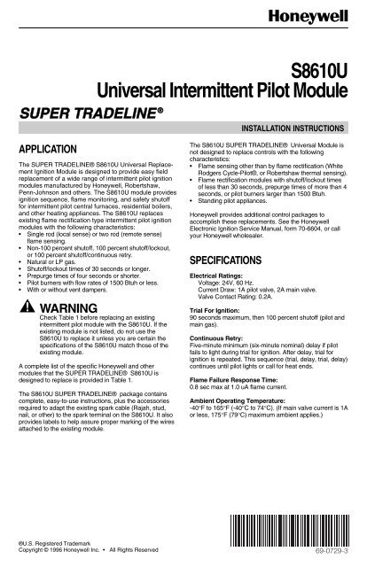
S8610U Universal Intermittent Pilot Module - Restaurant Equipment ...
S8610U Universal Intermittent Pilot Module - Restaurant Equipment ...
S8610U Universal Intermittent Pilot Module - Restaurant Equipment ...
Create successful ePaper yourself
Turn your PDF publications into a flip-book with our unique Google optimized e-Paper software.
69-0729—3 2<strong>S8610U</strong> UNIVERSAL INTERMITTENT PILOT MODULETable 1. <strong>S8610U</strong> Replaces these Ignition <strong>Module</strong>s.CamstatIPI-24-00Fenwal05-203025-00505-203026-005S86H1089S86H1097S86H1105S86H1121S86H1147S90A1005CSA42A-603RCSA42A-604RCSA43A-600RCSA44A-600RCSA45A-601RCSA45A-602RG60PAG-5G60PAG-6G60PAJ-1G60PAK-1G60PAK-2G60PFH-1G60RCG-2G60RCJ-1G60RDG-1G60RDK-1G60RGL-1G60RHL-1G67AG-8G67BG-2G67BG-3G67BG-4G67BG-5G67MG-1HoneywellS86A1001S86A1019S86A1027S86A1035S90B1003S90B1011S8600A1001S8600B1009S8600C1015S8600F1000CSA46A-600RCSA48A-600RCSA49A-600RCSA49A-605RCSA51A-601RCSA52A-600RG60PFH-2G60PFL-1G60PFQ-1G60PVL-1G60QAG-2G60QAG-3G60RHP-1G60RPL-1G60RSL-1G60ZAG-1G65BBG-1G65BBG-2G67MG-4G67NG-2G600AX-1G600AY-1G600MX-1G600NX-1S86B1009S86B1017S86B1025S86C1007S86C1015S86C1031S8600F1034S8600F1042S8600H1006S8600H1022S8600H1048S8600H1055G60AAA-1G60AAG-1G60AAG-3G60AAG-4G60AAG-5G60AAG-6G60QAK-1G60QBG-1G60QBG-2G60QBG-3G60QBG-4G60QBG-5G65BBG-3G65BBG-4G65BBG-5G65BBG-6G65BBG-7G65BBG-8G600RX-1G670AW-1G770MGA-1G770MGA-2G770MGC-1G770MGC-2S86C1049S86C1056S86D1005S86D1021S86E1002S86E1010S8600H1089S8600H1105S8600M1005S8600M1013S8610A1009S8610B1007G60CAA-1G60CAA-3G60CAG-1G60CAG-2G60CAG-3G60CAG-4G60QBG-6G60QBG-7G60QBG-8G60QBG-9G60QBH-1G60QBK-1G65BBM-1G65BBM-2G65BBM-3G65BBM-4G65BCG-1G65BCM-1G770MGC-3G770MHA-1G770NGA-1G770NGC-4G770NGC-5G770NGC-6S86E1028S86E1036S86E1044S86E1051S86E1069S86E1077S8610B1015S8610C1005S8610F1008S8610F1016S8610F1024S8610F1032G60CAG-5G60CAG-6G60CAG-7G60CAG-8G60CAG-9G60CBA-1G60QBK-3G60QBL-1G60QBL-2G60QCG-1G60QCJ-1G60QCL-1G65BFG-1G65BFMG65BKG-1G65BKG-2G65BKG-3G65BKM-1G770NGC-7G770RGA-1G770RHA-1G770MHA-2G770MHC-1G770NHA-1S86E1101S86E1119S86E1127S86F1000S86F1018S86F1026S8610H1012S8610H1038S8610H1046S8610H1053S8610H1079S8610M1003G60CBA-3G60CBG-1G60CBG-10G60CBG-11G60CBG-14G60CBG-16G60QDG-1G60QFL-1G60QHL-1G60QJL-1G60QLG-1G60QPL-1G65BKM-2G65BKM-3G65DBGG65DBM-1G65DBM-3G65DCM-1G770NHC-1G770RHA-2Robertshaw780-715S86F1042S86F1059S86F1067S86F1075S86F1083S86F1091S8610M1029S8620H1028HSC1003-3G60CBG-17G60CBG-3G60CBG-4G60CBG-9G60CCA-1G60CCG-1G60QRH-1G60QRL-1G60QRL-2G60QRL-3G60QSL-1G60QTH-1G65DFGG65DFM-1G65DKGG65DKMG65FBGG65FFG780-735780-737SP715SP715ASP735SP735DS86G1008S86G1016S86G1032S86G1057S86G1073S86H1006S86H1022S86H10481003-300Penn-JohnsonCSA35A-617RCSA35A-618RCSA42A-600RCSA42A-601RG60CPG-1G60DBG-1G60DCG-1G60DCG-2G60PAG-1G60PAG-2G60PAG-3G60PAG-4G60QTL-1G60RAG-1G60RAK-1G60RBG-1G60RBG-2G60RBG-3G60RBK-1G60RBK-2G65FKGG66AG-1G66BG-1G66MG-1G66NG-1G67AG-3G67AG-4G67AG-7SP735LUSI 715U
<strong>S8610U</strong> UNIVERSAL INTERMITTENT PILOT MODULEPLANNING THE INSTALLATIONWARNINGFIRE OR EXPLOSION HAZARDCAN CAUSE PROPERTY DAMAGE,SEVERE INJURY, OR DEATH.Follow these warnings exactly:1. Plan the installation as outlined below.2. Plan for frequent maintenance as described inthe Maintenance section.When intermittent pilot systems are used on centralheating equipment in barns, greenhouses, and commercialproperties and on heating appliances such ascommercial cookers, agricultural equipment, industrialheating equipment and pool heaters, heavy demands aremade on the controls. Special steps can be required toprevent nuisance shutdowns and control failure due tofrequent cycling, severe environmental conditions relatedto moisture, corrosive chemicals, dust or excessive heat.These applications require Honeywell Home andBuilding Control Engineering review; contact yourHoneywell Sales Representative for assistance.Review the following conditions that can apply to yourspecific installation and take the precautionary stepssuggested.Frequent CyclingThese controls are designed for use on appliances thattypically cycle three to four times an hour only during theheating season. In year-round applications with greatercycling rates, the control can wear out more quickly;perform a monthly checkout.Water or Steam CleaningIf a module or gas control gets wet, replace it. If theappliance is likely to be cleaned with water or steam,protect (cover) the controls and wiring from water orsteam flow. Mount the controls high enough above thebottom of the cabinet so they do not get wet duringnormal cleaning procedures. Use a NEMA 4 enclosurefor the ignition module; see the Electronic IgnitionService Manual, form 70-6604.High Humidity or Dripping WaterDripping water can cause the module to fail. Never installan appliance where water can drip on the controls.In addition, high ambient humidity can cause the gascontrol to corrode and fail.If the appliance is in a humid atmosphere, make sure aircirculation around the controls is adequate to preventcondensation. Also, regularly check out the system. ANEMA 4 enclosure is recommended for the ignitionmodule; see the Electronic Ignition Service Manual,form 70-6604.Corrosive ChemicalsCorrosive chemicals can attack the module and gascontrol, eventually causing a failure. If chemicals areused for routine cleaning, make sure they do not reachthe controls. Where chemicals are suspended in air, asin some industrial or agricultural applications, use aNEMA 4 enclosure for the ignition module; see theElectronic Ignition Service Manual, form 70-6604.Dust or Grease AccumulationHeavy accumulations of dust or grease can causecontrols to malfunction. Where dust or grease can be aproblem, provide covers for the module and the gascontrol to limit contamination. A NEMA 4 enclosure isrecommended for the ignition module; see the ElectronicIgnition Service Manual, form 70-6604.HeatExcessively high temperatures can damage controls.Make sure the maximum ambient temperature at thecontrol does not exceed the rating of the control. If theappliance operates at very high temperatures, useinsulation, shielding, and air circulation, as necessary, toprotect the controls. Proper insulation or shielding shouldbe provided by the appliance manufacturer; verify properair circulation is maintained when the appliance isinstalled.INSTALLATIONWhen Installing this Ignition System…1. Read these instructions carefully. Failure to followthem could damage the components or cause ahazardous condition.2. Check the ratings given in the instructions and onthe components to make sure they are suitable foryour application.3. Installer must be a trained, experienced servicetechnician.4. After installation is complete, check out componentoperation as provided in these instructions.WARNINGFIRE OR EXPLOSION HAZARDCAN CAUSE PROPERTY DAMAGE,SEVERE INJURY, OR DEATH.1. If the ignition module gets wet, it canmalfunction, leading to the accumulation ofexplosive gas.• Never install where water can flood, drip orcondense on the module.• Never use a module that has been wet.Replace it.2. Liquefied petroleum (LP) gas is heavier thanair and will not vent upward naturally.• Do not light the pilot or operate electricswitches, lights or appliances until you aresure the appliance area is free of gas.3. Do not attempt to disassemble or clean themodule. Improper reassembly and cleaningcan cause unreliable operation.CAUTION1. Disconnect power supply before beginningwiring to prevent electrical shock or equipmentdamage.2. If a new gas control is to be installed, turn offthe gas supply before starting installation.Conduct a Gas Leak Test according to thegas control manufacturer instructions afterthe gas control is installed.3. If the module must be mounted nearmoisture or water, provide a suitablewaterproof enclosure.4. Using the wire labels provided, label all wiresbefore they are disconnected. Wiring errorscan cause improper appliance operation anddangerous conditions such as bypassingsafety features.369-0729—3
<strong>S8610U</strong> UNIVERSAL INTERMITTENT PILOT MODULEPerform Preinstallation Safety InspectionThe preinstallation checks described in ANSI StandardZ21.71 in Exhibit A must be done before the replacementmodule is installed. If a condition that could result in unsafeoperation is detected, the appliance should be shut off andthe owner advised of the unsafe condition. Correct anypotentially unsafe condition before proceeding with theinstallation.Remove Old <strong>Module</strong>Disconnect power supply before doing any work on theunit. Disconnect and tag the wires from the old moduleusing the wire labels provided. Remove the old modulefrom its mounting location.Mount New Ignition <strong>Module</strong>We recommend mounting the <strong>S8610U</strong> <strong>Module</strong> in thesame location as the old module, if possible. Otherwise,select a location close enough to the burner to allow ashort (3 ft. (0.9 m) maximum), direct cable route to theigniter. Ambient temperature at the module must be withinthe range listed in the Application section. Connect the wires to the <strong>S8610U</strong> Ignition <strong>Module</strong> asshown in Tables 3 through 6. Make sure thatadequate system ground is provided as indicated inthe wiring tables. Verify the thermostat anticipator setting as explainedin the Important.NOTE:The wiring diagrams in Fig. 2 through 4 showtypical hookups with the <strong>S8610U</strong> Ignition <strong>Module</strong>and should be used for reference only.MOUNT IN ONE OF THESE POSITIONSTERMINALS FACING DOWNMount the module with the terminals down to protectthem from dripping water and dust. The module can alsobe mounted with the terminals on either side. Do notmount with the terminals pointing up. Refer to Fig. 1 formounting recommendations. When it is necessary to drillnew mounting holes, use the <strong>S8610U</strong> as a template tomark mounting hole pattern. Drill new holes, as required.Fasten securely with four No. 6-32 machine or No. 8sheetmetal screws.Wire the <strong>Module</strong>CAUTION1. Check the wiring diagram furnished by theappliance manufacturer, if available, andcompare with Tables 3 through 6. Carefullyfollow any special instructions affecting thegeneral wiring procedures outlined below.2. Disconnect the power supply before makingwiring connections to prevent electrical shockor equipment damage.IMPORTANT1. A common ground is required on:a. The pilot burner mounting bracket, andb. The GND (BURNER) terminal on the ignitionmodule. Failure to use the GND (BURNER)terminal can result in intermittent loss of sparkand/or loss of flame current sensitivity.2. Make sure the transformer has adequate VA.The ignition module requires at least 0.2A at 24Vac. Add the current draws of all other devices inthe control circuit, including the pilot and mainvalves in the gas control, and multiply by 24 todetermine the total VA requirement of thesecomponents. Add this total to 4.8 VA (for theignition module). The result is the minimumtransformer VA rating. Use a Class II transformerwhen replacement is required.3. When a vent damper is connected to the <strong>S8610U</strong>vent damper connector, be sure the systemtransformer delivers at least 30 VA. The <strong>S8610U</strong>has an internal fuse that is intended to preventappliance lightoff if the vent damper is not inplace or wired properly. Using a small transformercan interfere with the proper operation ofthe fuse and bypass the intended safety feature.Fig. 1. <strong>Module</strong> mounting recommendations.Modify Ignition Cable, If NecessaryUse existing ignition cable if it is in good condition. If theexisting ignition cable does not have a 1/4 in. quickconnecton the module end, either use the Rajah adapteror strip the wire and replace with the 1/4 in. insulatedquick-connect supplied. If the cable must be replaced,order a Honeywell ignition cable, see Table 2. It might benecessary to replace the connector at the pilot burner endto match the pilot burner spark termination.NOTE:TERMINALS FACING LEFTTERMINALS FACING RIGHTDO NOT MOUNTWITH TERMINALS FACING UPM2647When using an <strong>S8610U</strong> to replace an S86, usethe enclosed adapter to convert the S86 IgnitionCable to an <strong>S8610U</strong> Ignition Cable. Then,install the adapter and cable to the <strong>S8610U</strong>Ignition <strong>Module</strong>.69-0729—3 4
<strong>S8610U</strong> UNIVERSAL INTERMITTENT PILOT MODULECable PartNumberLength<strong>Module</strong>End394800-30 30 in. 1/4 in.quickconnect,insulated394801-30 30 in. 1/4 in.quickconnect,insulatedIgniter EndRajah connectorreceptacle, 90degree rubberbootRajah connectorreceptacle,straight rubberbootNOTE:The cable must not run in continuous contactwith a metal surface or spark voltage is greatlyreduced. Use ceramic or plastic standoffinsulators, as required.Arc LengthNo arc or arcless than 1/8 in.(3 mm)Arc 1/8 in. (3 mm)or longer.Arc TableActionCheck external fuse, if provided.Verify power at module inputterminal. Replace module if fuseand power are okay.Voltage output is okay.Table 3. Conversion from Honeywell S86, S90, S8600 and S8610 to <strong>S8610U</strong>1003.ReplacementControlOld ControlTerminalFunction <strong>S8610U</strong>1003 S86A,C S86B,D S86E,F,G,HMain valveoperatorMain valveand pilotcommon<strong>Pilot</strong> valveoperatorBurnergroundconnectionTransformersecondary(unswitchedleg)Transformersecondary(switchedleg)FlamesensorIgniter/sensorTable 2. Honeywell Preassembled IgnitionCables (UL Style 3257).S8600A,B,CS8610A,B,CS90A,BS8600F,H,MS8610F,H,MMV MV MV MV MV MVMV/PV MV/PV MV/PV MV/PV MV/PV MV/PVPV PV PV PV PV PVGND(BURNER)GND GND GND(BURNER)GND(BURNER)GND(BURNER)24V GND 25V (1) 25V (GND) 25V (1) e 24V GND 24V GNDProcedural Notes24V* 25V (2) 25V 25V (2)e* 24V* 24V* * Important: If the old module had a ventdamper plug but a vent damper was notinstalled, or if it did not have a ventdamper plug: leave the vent damper plugin position on the S8610 and connect the25V (2) or 24V wire from the old moduleto the TH-W terminal on the <strong>S8610U</strong>. Donot use the 24V terminal on the<strong>S8610U</strong>.25V (2) or 24V used only in systems whereplug-in cable connects damper to module.TH-W TH-Ra TH-Ra TH-Ra TH-W (Thisterminalnot included onS90.)TH-W b TH-W TH-W bSENSEf d d d SENSEf dTH-WSPARK IGN COILc IGN COILc IGN COILc SPARK SPARKIf the old module had a vent damper witha plug connection to a Molex connector,wire the terminals as indicated in thetable.a If 25V (2) and TH-R have wires connected, disconnect and splice together with solderless connector.b If TH-R and TH-W are jumpered together, connect 25V (2) lead from S86 to TH-W on <strong>S8610U</strong>1003.c Use Rajah to quick connector adapter (supplied) or cut Rajah connector off ignition cable at module end; attach insulated quickconnect for connection to S8610.d Leave black jumper connected.e Terminals may be marked 25V on some models and 24V on later models. These are functionally equivalent.f On dual igniter and sensor models, remove jumper quick connect from <strong>S8610U</strong>1003 Sense terminal, cut jumper wire at circuit board,and discard.569-0729—3
<strong>S8610U</strong> UNIVERSAL INTERMITTENT PILOT MODULETable 4. Conversion from Robertshaw SP715 and SP735C to <strong>S8610U</strong>1003 (Includes 780-XXX and USI715U).Terminal FunctionReplacementControlOld Control SP715 and SP735(includes 780-XXX and USI 715U) c,dHoneywell<strong>S8610U</strong>1003 7000D Valve 7100D Valve 7100K Valve Procedural NotesMain valve operator MV MV(to: Valve TH)Main valve and pilotcommonMV/PVMV/PV(to: Valve TR)<strong>Pilot</strong> valve operator PV PV(to: ValvePILOT)*BurnerconnectiongroundGND(BURNER)MV(to: Valve M)MV/PV(to: Valve C)PV(to: Valve P)MV(to: Valve TR)PV(to: Valve C and TH)PV(to: Valve PICK &HOLD)GND GND GND —Transformer24V GND TR TR TR —secondary(unswitched leg) 24V No connection NoconnectionNo connection —Transfomersecondary(switched leg)——*This is the terminal notjumpered to TR.E3 a E3 a E3 a When supplied, E3provides connection toLockout Timer.TH-W TH TH TH If LO-15 is part of theinstallation, use thewire disconnected fromE1 tagged Thermostat.Flame sensor SENSE b SENSE e SENSE e SENSE e —<strong>Pilot</strong> igniter SPARK IGN IGN IGN —1. Use existing wiring harness to make connections to S8610 per table. IMPORTANT: If installation includes LO-15Lockout Timer, discard wires to E3 and TH. Disconnect and retain wire to LO-15 terminal E1. Tag wire,Thermostat.Discard LO-15.2. On 7000D series valve, retain (or install) white jumper between valve TR and pilot solenoid.a If LO-15 Lockout timer is not installed, E3 connector provided on SP715 is not used.b Important: If the USI 715U with combination igniter sensor is not used, remove black jumper quick connect fromSense terminal of <strong>S8610U</strong>1003. Cut jumper wire at circuit board and discard.c For replacement of Robertshaw Flame Switch systems (SP710, 720, 730, 750, 780-700, 780-701, 780-710, 780-711,780-712 and 780-713), see Honeywell Ignition Control Handbook.d 780-715 and USI 715U are equivalent to SP715; 780-735 and 780-737 are equivalent to SP735. For other 780-XXXmodels, see notec.e OPT. SENSOR on USI 715U. No external connection if combination igniter sensor is used.69-0729—3 6
<strong>S8610U</strong> UNIVERSAL INTERMITTENT PILOT MODULETable 5. Conversion from Penn-Johnson CSA—(All), G60, G65, G66, G67, G600, G670 Or G770 to <strong>S8610U</strong>1003.TerminalFunctionMain valveoperatorMain valve andpilot common<strong>Pilot</strong> valveoperatorBurner groundconnectionTransformersecondary(unswitched leg)Transformersecondary(switched leg)ReplacementControlHoneywellS861U1003Old ControlCSA45A-600R d , G60, G65, G66, G67,G600 OR G670 Installation withLockout <strong>Module</strong>s as follows:*None (Y79)Y79AmoduledMV 3 3 Y79B MV MV (3)Y79Bmodulec G770 Procedural NotesMV/PV GR GR GR GROUND(5)PV 1 1 Y79B PV PV (1)GND(BURNER)GR GR GR GROUND24V GND GR GR GR GROUNDTH-W* 2a Y79 THSb 2 TH-S (2)24V* Noconnection*Noconnection*Noconnection*Noconnection*Flame sensor SENSE* 4 e 4 e 4 e SENSE (4) e<strong>Pilot</strong> igniter SPARK IGN COIL IGN COIL IGN COIL IGN COIL It might benecessary to cut offRajah connectorand/or attachinsulated quickconnect.a Discard wire between transformer and terminal 5 (G60) or 6 (G600); otherwise, use existing harness for wiring.b Discard wires between Y79A and module as follows: Red to 3, Black to 2, White to GR. Discard wire betweentransformer and 6.c Discard wires between Y79B and module as follows: White to 3, Black to 1, Brown to GR. Discard wire betweentransformer and 6.d CSA code numbers (for example, CSA45A-600R) are equivalent to G600 and use the same wiring information tables.e Important: Remove black jumper quick connect from Sense terminal of <strong>S8610U</strong>1003; cut jumper wire at circuit boardand discard.*IF INSTALLATION DOES NOT INCLUDE VENT DAMPER WITH PLUG CONNECTION TO MODULE:1. Leave vent damper plug on <strong>S8610U</strong> <strong>Module</strong> in position.2. Use TH-W terminal.*IF INSTALLATION INCLUDES VENT DAMPER WITH PLUG CONNECTION TO MODULE:1. Replace <strong>S8610U</strong> <strong>Module</strong> vent damper plug with damper Molex connector.2. Wire thermostat W wire to TH-W.3. Run wire from switched leg of transformer secondary to both thermostat R and S8610 <strong>Module</strong> 24V terminals.769-0729—3
<strong>S8610U</strong> UNIVERSAL INTERMITTENT PILOT MODULETerminalFunctionMain valveoperatorMain valve andpilot common<strong>Pilot</strong> valveoperatorBurner groundconnectionTransformersecondary(unswitched leg)Transformersecondary(switched leg)Table 6. Conversion from Camstat, Fenwal or HSC to <strong>S8610U</strong>1003.ReplacementControlHoneywell<strong>S8610U</strong>1003CAMSTATIPI-24-00aOld ControlFENWAL05-20XbHSC 1003-3and 1003-300aMV MV MAIN VALVE MV —Procedural NotesMV/PV GND GROUND GND/COM Fenwal only: run separatelead to S8610 valvecommon terminal.PV PV PILOT VALVE PV —GND(BURNER)GND — — To assure good ground, runseparate wire from pilotburner to S8610 GND(BURNER).24V GND T2 GROUND GND/COM —24V No connection No connection No connection —TH-W T1 POWER 24 VAC —Flame sensor SENSE S c — SENSOR c —<strong>Pilot</strong> igniter SPARK IGN H.V. IGN COIL Strip module end of ignitioncable as necessary andattach insulated quickconnect for connection toS8610.a Use existing wiring harness to make connections to S8610.b Tag all wires at module connector with terminal designations. Cut wires at connector, attach quick connects andconnect to S8610; per table.c Important: Remove black jumper quick connect from Sense terminal of <strong>S8610U</strong>1003; cut jumper wire at circuit boardand discard.69-0729—3 8
<strong>S8610U</strong> UNIVERSAL INTERMITTENT PILOT MODULE<strong>S8610U</strong>MV MV/PV PVGND(BURNER)24VGND 24V TH-W5VENTDAMPERPLUG SENSE SPARKPILOTCOMMAINVALVE76WIRINGHARNESS31ST 2NDOPERATOR OPERATORDUAL VALVE COMBINATIONGAS CONTROLTHERMOSTAT2D892 VENTDAMPERSENSOR4LIMITCONTROLLER 1L1(HOT)L2IGNITERGROUND8PILOT GASSUPPLY1234POWER SUPPLY. PROVIDE DISCONNECT MEANS AND OVERLOAD PROTECTION AS REQUIRED.ALTERNATE LIMIT CONTROLLER LOCATION.MAXIMUM CABLE LENGTH 3 ft (0.9m).CONTROLS IN 24V CIRCUIT MUST NOT BE GROUND LEG TO TRANSFORMER.5REMOVE PLUG ONLY IF USING VENT DAMPER. FUSE BLOWS ON STARTUP WHEN PLUG ISREMOVED AND VENT DAMPER WIRING HARNESS IS INSTALLED; THEN MODULE OPERATESONLY WHEN VENT DAMPER IS CONNECTED.6REMOVE JUMPER AND CONNECT SENSE TERMINAL ON TWO ROD APPLICATION ONLY.7 IF THE VENT DAMPER IS CONNECTED, WIRE 24V TERMINAL, AS SHOWN. CONNECT VENTDAMPER CABLE IN PLACE OF PLUG SHIPPED WITH THE <strong>S8610U</strong>. IF NO VENT DAMPER ISCONNECTED, DO NOT WIRE 24V TERMINAL.M2641D8 30 VA MINIMUM WHEN VENT DAMPER IS CONNECTED TO DAMPER PLUG.Fig. 2. <strong>S8610U</strong> in heating system with atmospheric burner.<strong>S8610U</strong>MV MV/PV PVGND(BURNER)24VGND 24V TH-W5VENTDAMPERPLUG SENSE SPARKPILOT COMMAINVALVE1ST 2NDOPERATOR OPERATORDUAL VALVE COMBINATIONGAS CONTROLSENSORAIRPROVINGSWITCHCOMBUSTIONAIR BLOWERRELAY6 3THERMOSTAT24IGNITERPILOT GASSUPPLYPILOTBURNERGROUND1L1 L2 COMBUSTION(HOT) AIR BLOWERMOTORCONTROLLER1L2 L1(HOT)LIMITCONTROLLER12345POWER SUPPLY. PROVIDE DISCONNECT MEANS AND OVERLOAD PROTECTION AS REQUIRED.ALTERNATE LIMIT CONTROLLER LOCATION.MAXIMUM CABLE LENGTH 3 ft (0.9m).CONTROLS IN 24V CIRCUIT MUST NOT BE GROUND LEG TO TRANSFORMER.LEAVE VENT DAMPER PLUG CONNECTED.6 REMOVE JUMPER AND CONNECT SENSE TERMINAL ON TWO ROD APPLICATION ONLY. M2642BFig. 3. <strong>S8610U</strong> in heating system with power-assisted combustion.969-0729—3
<strong>S8610U</strong> UNIVERSAL INTERMITTENT PILOT MODULESTARTTHERMOSTAT (CONTROLLER)CALL FOR HEATSTAGE 1TRIAL FORIGNITIONSPARK GENERATOR POWEREDFirst valve (pilot) operator opens<strong>Pilot</strong> burner lights.<strong>Module</strong> sensesflame current.ORPILOT BURNER OPERATIONAfter 90 seconds maximum, system shuts off; trial forignition restarts after minimum of 5 minutes (6 minutesnominal). Ignition, shutoff, wait sequence repeats untilpilot lights or call for heat ends.STAGE 2MAIN BURNEROPERATIONENDFLAME CURRENT SENSED• Spark generator off.• Second valve operator(main) opens.MAIN BURNER OPERATION<strong>Module</strong> monitors pilotflame current.THERMOSTAT (CONTROLLER)SATISFIEDValves close, pilot and mainburners are off.POWER INTERRUPTIONSystem shuts off, restarts when poweris restored.PILOT FLAME FAILUREMain valve closes.<strong>Module</strong> starts trial for ignition.M2640ASTARTUP AND CHECKOUTFig. 4. <strong>S8610U</strong> in typical ST9120 application.Check out the gas control system:• At initial installation of the appliance.• As part of regular maintenance procedures.• At maintenance intervals determined by the application.• As the first step in troubleshooting.• Any time work is done on the system.Maintenance frequency must be determined individuallyfor each application; see Maintenance section.WARNINGFIRE OR EXPLOSION HAZARDCAN CAUSE PROPERTY DAMAGE,SEVERE INJURY, OR DEATH.1. If you smell gas or suspect a gas leak, turn offthe gas at the manual service valve andevacuate the building. Do not try to light anyappliance; do not touch any electrical switchor telephone in the building until you are sureno spilled gas remains.2. Gas leak test must be done as described inSteps 1 and 6 below during initial installationand anytime work is done involving the gaspiping.Step 1: Perform visual inspection.a. With power off, make sure all wiring connections areclean and tight.b. Turn on the power to the appliance.c. Open the manual shutoff valves in the gas line to theappliance.d. Test for gas leak before gas control if piping has beendisturbed.Gas Leak Test:Paint the gas control gasket edges and all pipe connectionsdownstream of the gas control, including the pilottubing connections, with a rich soap and water solution.Bubbles indicate gas leaks. Tighten the joints and screwsor replace component to stop gas leak. Recheck with soapand water solution.Step 2: Verify control system ground.The igniter, flame sensor, and ignition module must sharea common ground with the main burner. Use thermoplasticinsulated wire with a minimum rating of 105°C (221°F) forthe ground wire; asbestos insulation is not acceptable. Ifthe temperature at the wire could exceed 105°C (221°F),use a shield to protect the wire from radiant heat generatedby the burner. Connect the ground wire as follows:a. Fit one end of the ground wire with a female 1/4 in.quick-connect terminal and connect it to the malequick-connect GND (BURNER) terminal on theignition module.b. Strip the other end of the wire and fasten it under theigniter bracket mounting screw. If necessary, use ashield to protect the ground wire from radiant heat.c. The burner serves as the common grounding area. Ifthere is not good metal-to-metal contact between theburner and ground, run a lead from the burner toground.NOTE:Earth ground is not required.69-0729—3 10
<strong>S8610U</strong> UNIVERSAL INTERMITTENT PILOT MODULEStep 3: Review normal operating sequenceand module specifications.a. See Operation and Application sections.Step 4: Reset the module.a. Turn the thermostat to its lowest setting.b. Wait one minute.As you do Steps 4 and 5, watch for points where operationdeviates from normal. Refer to Troubleshooting Guide, Fig.7, to correct problem.Step 5: Check safety shutoff operation.a. Turn off the gas supply.b. Set the thermostat or controller above the roomtemperature to call for heat.c. Watch for spark at pilot burner.d. Time spark from start to shutoff. Spark should shutoff after 90 seconds maximum. Ignition sequencerepeats after five minutes minimum.e. Open manual gas control knob and make sure nogas is flowing to pilot or main burner.f. Set the thermostat below the room temperature andwait one minute before continuing.Step 6: Check normal operation.a. Set the thermostat or controller above the roomtemperature to call for heat.b. Make sure the pilot lights smoothly when the gasreaches the pilot burner.c. Make sure the main burner lights smoothly withoutflashback.d. Make sure the burner operates smoothly withoutfloating, lifting, or flame rollout to the furnacevestibule or heat buildup in the vestibule.e. If the gas line has been disturbed, complete the gasleak test.Gas Leak Test:Paint the gas control gasket edges and all pipe connectionsdownstream of the gas control, including pilottubing connections, with a rich soap and water solution.Bubbles indicate gas leaks. Tighten the joints andscrews or replace component to stop gas leak. Recheckwith soap and water solution.f. Turn the thermostat or controller below the roomtemperature. Make sure the main burner and pilotflames go out.MAINTENANCEWARNINGFIRE OR EXPLOSION HAZARDCAN CAUSE PROPERTY DAMAGE,SEVERE INJURY, OR DEATH.Do not attempt to take the module apart or to cleanit. Improper assembly and cleaning can causeunreliable operation.Regular preventive maintenance is important in applicationsthat place a heavy load on system controls, such asin the commercial cooking and agricultural and industrialindustries because:• In many applications, particularly commercial cooking,the equipment operates 100,000 to 200,000 cyclesper year. Such heavy cycling can wear out the gascontrol in one to two years.• Exposure to water, dirt, chemicals and heat candamage the gas control and shut down the controlsystem. A NEMA 4 enclosure can reduce exposure toenvironmental contaminants. See electronic IgnitionService Manual, form 70-6604.The maintenance program should include regular systemcheckout as outlined in the Startup and Checkoutsection, and the control system as described in theappliance manufacturer literature.Maintenance frequency must be determined individuallyfor each application. Some considerations are:• Cycling frequency. Appliances that can cycle 20,000times annually should be checked monthly.• <strong>Intermittent</strong> use. Appliances that are used seasonallyshould be checked before shutdown and again beforethe next use.• Consequence of unexpected shutdown. Where thecost of an unexpected shutdown would be high, thesystem should be checked more often.• Dusty, wet, or corrosive environment. Because theseenvironments can cause the gas control to deterioratemore rapidly, the system should be checked moreoften.Any control should be replaced if it does not performproperly on checkout or troubleshooting. In addition,replace any module if it is wet or looks like it has everbeen wet. Protective enclosures, as described inPlanning the Installation section, are recommendedregardless of checkout frequency.1169-0729—3
<strong>S8610U</strong> UNIVERSAL INTERMITTENT PILOT MODULESTARTTURN OFF GAS SUPPLY.TURN THERMOSTAT(CONTROLLER) TO CALLFOR HEAT.NOTE: Before troubleshooting, familiarize yourself with the startup and checkout procedure.POWER TO MODULE.(24V NOMINAL)CHECK AT TH-W TERMINAL,AND ALSO AT 24V TERMINALIF A VENT DAMPER ISCONNECTED TO THEDAMPER CONNECTOR.NOCheck line voltage power, low voltage transformer, limit controller, thermostat (controller) and wiring. Also,check air proving switch on combustion air blower system (if used) and verify that vent damper (if used) is openand end switch is made.YESSPARK ACROSSIGNITER/SENSOR GAP?YESNOPull ignition lead andcheck spark at module.Spark okay?YESNO• On models with vent damper plug, make sure vent damperwas not installed, then removed. Replace vent damper,if necessary.• On other models, replace module.• Check ignition cable, ground wiring, ceramic insulator and gap, and correct.• Check boot of the ignition cable for signs of melting or buckling. Replace cable and take protective actionto shield cable and boot from excessive temperatures.TURN ON GAS SUPPLY.PILOT BURNER LIGHTS?YESNO• Check that all manual gas valves are open, supply tubing and pressures are good, and pilot burner orificeis not blocked.• Check electrical connections between module and pilot operator on gas control.• Check for 24 Vac across PV-MV/PV terminals on module. If voltage is okay, replace gas control; if not,replace moduleSPARK STOPS WHENPILOT IS LIT?YESNO• Check continuity of ignition cable and ground wire.• Clean flame rod.• Check electrical connections between flame rod and module.• Check for cracked ceramic flame rod insulator.• Check that pilot flame covers flame rod and is steady and blue.• Adjust pilot flame.• If problem persists, replace module.MAIN BURNER LIGHTS?YESNO• Check for 24 Vac across MV-MV/PV terminals. If no voltage, replace module.• Check electrical connections between module and gas control. If okay, replace gas control or gascontrol operator.SYSTEM RUNS UNTILCALL FOR HEAT ENDS?YESNO• Check continuity of ignition cable and ground wire.NOTE: If ground is poor or erratic, shutdowns can occur occasionally even though operation is normalat the time of checkout.• Check temperature at igniter-sensor insulator. High temperatures can cause a short.• Check that pilot flame covers flame rod and is steady and blue.• If checks are okay, replace module.CALL FOR HEAT ENDS.SYSTEM SHUTS OFF?YESNO• Check for proper thermostat (controller) operation.• Remove MV lead at module; if valve closes, recheck temperature controller and wiring; if not, replacegas control.TROUBLESHOOTINGENDS.Repeat procedure until troublefree operation is obtained.M2643BFig. 5. <strong>S8610U</strong> normal operating sequence.69-0729—3 12
<strong>S8610U</strong> UNIVERSAL INTERMITTENT PILOT MODULEOPERATION<strong>Module</strong> operation can be conveniently divided into twophases for the S8610:• Trial for ignition.• Main burner operation.Fig. 5 summarizes the normal module operating sequence.TROUBLESHOOTINGIMPORTANT1. The following service procedures are provided asa general guide. Follow appliance manufacturerservice instructions if available.2. Meter readings between gas control and ignitionmodule must be taken within the trial for ignitionperiod. Once the ignition module shuts off, waitfor retry or reset at the thermostat.3. If any component does not function properly,make sure it is correctly installed and wiredbefore replacing it.4. The ignition module cannot be repaired. If itmalfunctions, replace it.5. Only trained, experienced service techniciansshould service intermittent pilot systems.6. After servicing, verify proper system operation.Perform the checkout step in the Startup and Checkoutsection as the first step in troubleshooting. Then check theTroubleshooting Guide (Fig. 7) and the schematic diagram(Fig. 8) to determine the exact cause of the problem. Iftroubleshooting indicates an ignition problem, see IgnitionSystem Checks section to isolate and correct the problem.After troubleshooting, perform the checkout proceduresagain to be sure system is operating normally.Ignition System ChecksStep 1: Check ignition cable.Make sure:a. Ignition cable does not run in contact with any metalsurfaces.b. Ignition cable is no more than 36 in. (0.9m) long.c. Connections to the ignition module and to the igniteror igniter-sensor are clean and tight.d. Ignition cable provides good electrical continuity.Step 2: Check ignition system grounding. Nuisanceshutdowns are often caused by a poor orerratic ground.a. A common ground, usually supplied by the pilotburner bracket, is required for the module and thepilot burner/igniter-sensor.• Check for good metal-to-metal contact betweenthe pilot burner bracket and the main burner.• Check the ground lead from the GND (BURNER)terminal on the module to the pilot burner. Makesure connections are clean and tight. If the wire isdamaged or deteriorated, replace it with No. 14through 18 gauge, moisture-resistant, thermoplasticinsulated wire with 105°C (221°F) minimumrating.— Check the ceramic flame rod insulator forcracks or evidence of exposure to extremeheat, which can permit leakage to ground.Replace pilot burner/igniter-sensor andprovide shield, if necessary.— If flame rod or bracket are bent out of position,restore to correct position.Step 3: Check spark ignition circuit. You will needa short jumper wire made from ignition cable orother heavily insulated wire.a. Close the manual gas valve.b. Disconnect the ignition cable at the SPARK terminalon the module.WARNINGELECTROCUTION HAZARDCAN CAUSE SERIOUS INJURYOR DEATH.When performing the following steps, do not touchstripped end of jumper or SPARK terminal. Theignition circuit generates over 10,000 volts andelectrical shock can result.c. Energize the module and immediately touch oneend of the jumper firmly to the GND terminal on themodule. Move the free end of the jumper slowlytoward the SPARK terminal until a spark is established.d. Pull the jumper slowly away from the terminal andnote the length of the gap when sparking stops, checkas follows:1369-0729—3
<strong>S8610U</strong> UNIVERSAL INTERMITTENT PILOT MODULEStep 4: Check pilot and main burner lightoff.a. Set the thermostat to call for heat.b. Watch the pilot burner during the ignition sequence tobe sure:• Ignition spark continues after the pilot is lit.• <strong>Pilot</strong> lights and the spark stops, but the mainburner does not light.• <strong>Pilot</strong> lights, the spark stops and the main burnerlights, but the system shuts down.c. If so, verify adequate flame current as follows:• Turn off the furnace at the circuit breaker or fusebox.• Clean the flame rod with an emery cloth.• Make sure the electrical connections are clean andtight. Replace the damaged wire with moistureresistantNo. 18 wire rated for continuous duty upto 105°C (221° F).• Check for a cracked ceramic insulator, which cancause short to ground, and replace the ignitersensoror sensor, if necessary.• At the gas control, disconnect the main valve wirefrom the TH or MV terminal.• Turn on the power and set the thermostat to callfor heat. The pilot should light but the main burnerremains off because the main valve actuator isdisconnected.• Check the pilot flame. Make sure it is blue, steadyand envelops 3/8 to 1/2 in. (10 to 13 mm) of theflame rod. See Fig. 6 for possible flame problemsand the causes.• If necessary, adjust the pilot flame by turning thepilot adjustment screw on the gas controlclockwise to decrease or counterclockwise toincrease the pilot flame. Following adjustment,always replace the pilot adjustment cover screwand tighten firmly to assure proper gas controloperation.• Set the thermostat below the room temperature toend the call for heat.d. Recheck ignition sequence as follows:• Reconnect the main valve wire.• Set the thermostat to call for heat.• Watch the ignition sequence at the burner.• If spark continues after the pilot lights, replace theignition module.• If the main burner does not light or if the mainburner lights but the system locks out, check themodule, ground wire, and gas control, as describedin the Troubleshooting Guide, see Fig. 7.APPEARANCESMALL BLUE FLAMELAZY YELLOW FLAMEWAVING BLUE FLAMENOISY LIFTING BLOWING FLAMEHARD SHARP FLAMECAUSECHECK FOR LACK OF GAS FROM:• CLOGGED ORIFICE FILTER• CLOGGED PILOT FILTER• LOW GAS SUPPLY PRESSURE• PILOT ADJUSTMENT AT MINIMUMCHECK FOR LACK OF AIR FROM:• DIRTY ORIFICE• DIRTY LINT SCREEN, IF USED• DIRTY PRIMARY AIR OPENING,IF THERE IS ONE• PILOT ADJUSTMENT AT MINIMUMCHECK FOR:• EXCESSIVE DRAFT AT PILOTLOCATION• RECIRCULATING PRODUCTSOF COMBUSTIONCHECK FOR:• HIGH GAS PRESSURETHIS FLAME IS CHARACTERISTICOF MANUFACTURED GASCHECK FOR:• HIGH GAS PRESSURE• ORIFICE TOO SMALLM2233AFig. 6. Examples of unsatisfactory pilot flames.69-0729—3 14
<strong>S8610U</strong> UNIVERSAL INTERMITTENT PILOT MODULESTARTTURN OFF GAS SUPPLY.TURN THERMOSTAT(CONTROLLER) TO CALLFOR HEAT.NOTE: Before troubleshooting, familiarize yourself with the startup and checkout procedure.POWER TO MODULE.(24V NOMINAL)CHECK AT TH-W TERMINAL,AND ALSO AT 24V TERMINALIF A VENT DAMPER ISCONNECTED TO THEDAMPER CONNECTOR.NOCheck line voltage power, low voltage transformer, limit controller, thermostat (controller) and wiring. Also,check air proving switch on combustion air blower system (if used) and verify that vent damper (if used) is openand end switch is made.YESSPARK ACROSSIGNITER/SENSOR GAP?YESNOPull ignition lead andcheck spark at module.Spark okay?YESNO• On models with vent damper plug, make sure vent damperwas not installed, then removed. Replace vent damper,if necessary.• On other models, replace module.• Check ignition cable, ground wiring, ceramic insulator and gap, and correct.• Check boot of the ignition cable for signs of melting or buckling. Replace cable and take protective actionto shield cable and boot from excessive temperatures.TURN ON GAS SUPPLY.PILOT BURNER LIGHTS?YESNO• Check that all manual gas valves are open, supply tubing and pressures are good, and pilot burner orificeis not blocked.• Check electrical connections between module and pilot operator on gas control.• Check for 24 Vac across PV-MV/PV terminals on module. If voltage is okay, replace gas control; if not,replace moduleSPARK STOPS WHENPILOT IS LIT?YESNO• Check continuity of ignition cable and ground wire.• Clean flame rod.• Check electrical connections between flame rod and module.• Check for cracked ceramic flame rod insulator.• Check that pilot flame covers flame rod and is steady and blue.• Adjust pilot flame.• If problem persists, replace module.MAIN BURNER LIGHTS?YESNO• Check for 24 Vac across MV-MV/PV terminals. If no voltage, replace module.• Check electrical connections between module and gas control. If okay, replace gas control or gascontrol operator.SYSTEM RUNS UNTILCALL FOR HEAT ENDS?YESNO• Check continuity of ignition cable and ground wire.NOTE: If ground is poor or erratic, shutdowns can occur occasionally even though operation is normalat the time of checkout.• Check temperature at igniter-sensor insulator. High temperatures can cause a short.• Check that pilot flame covers flame rod and is steady and blue.• If checks are okay, replace module.CALL FOR HEAT ENDS.SYSTEM SHUTS OFF?YESNO• Check for proper thermostat (controller) operation.• Remove MV lead at module; if valve closes, recheck temperature controller and wiring; if not, replacegas control.TROUBLESHOOTINGENDS.Repeat procedure until troublefree operation is obtained.Fig. 7. <strong>S8610U</strong> Troubleshooting Guide.M2643B1569-0729—3
<strong>S8610U</strong> UNIVERSAL INTERMITTENT PILOT MODULEL1(HOT)ON-OFFSWITCHLIMITCONTROLLER1L2TH-WTHERMOSTAT2224VTRANSFORMER24V24V(GND)3FUSE1 5 3 6 2 41 5 3 6 2 4LOWVOLTAGEPOWERSUPPLY1K2K3KFLAMEDETECTORCIRCUITRELAYDRIVERS2K1SPARKDRIVECIRCUITHYBRID CIRCUITSTIMINGCIRCUITSARCGAPSENSESPARKSENSOR4IGNITER5GND(BUR-NER)BURNERGROUNDVENTDAMPERPLUGYELLOW1K1 1K2 3K22K23K11 POWER SUPPLY. PROVIDE DISCONNECT MEANS AND OVERLOAD PROTECTION AS REQUIRED.2 ALTERNATE LIMIT CONTROLLER LOCATION.3 3 AMP NONREPLACEABLE FUSE. FUSE BLOWS WHEN VENT DAMPER IS PLUGGED IN AND POWER IS APPLIED.4 SEPARATE SENSOR IS USED ON TWO-ROD SYSTEMS ONLY. DISCONNECT BLACK JUMPER WIRE FROM SENSETERMINAL, CUT AT CIRCUIT BOARD AND DISCARD.5 SINGLE ROD SYSTEM HAS IGNITER–SENSOR.MVPVMAINVALVEPILOTVALVEMV/PVINTERNAL WIRINGEXTERNAL WIRINGM2646BFig. 8. Schematic for <strong>S8610U</strong>.69-0729—3 16
<strong>S8610U</strong> UNIVERSAL INTERMITTENT PILOT MODULEANSI STANDARDSExhibit ARecommended Procedure for Safety Inspection of an Existing Appliance Installation as A PreliminaryStep to Applying an Automatic <strong>Intermittent</strong> <strong>Pilot</strong> SystemThe following procedure is intended as a guide to aid in determining that an appliance is properly installed and is in asafe condition for continuing use.This procedure is predicated on central furnace and boiler installations equipped with an atmospheric gas burner(s) andnot of the direct vent type. It should be recognized that generalized test procedures cannot anticipate all situations.Accordingly, in some cases, deviation from this procedure may be necessary to determine safe operation of theequipment.a. This procedure should be performed prior to any attempt at modification of the appliance or the installation.b. If it is determined there is a condition which could result in unsafe operation, the appliance should be shut off andthe owner advised of the unsafe condition.The following steps should be followed in making the safety inspection: Conduct a Gas Leakage Test of the appliance piping and control system downstream of the shutoff valve in thesupply line to the appliance. Visually inspect the venting system for proper size and horizontal pitch and determine there is no blockage orrestrictions, leakage or corrosion or other deficiencies that could cause an unsafe condition. Shut off all gas to the appliance and shut off any other fuel-burning appliance within the same room. Use theshutoff valve in the shutoff valve in the supply line to each appliance. Inspect burners and crossovers for blockage and corrosion. Applicable only to warm air heating appliances. Inspect heat exchangers for cracks, openings or excessivecorrosion. Applicable only to boilers. Inspect for evidence of water or combustion product leaks. Insofar as is practical, close all building doors and windows and all doors between the space in which the applianceis located and other spaces of the building. Turn on clothes dryers. Turn on any exhaust fans, such as rangehoods and bathroom exhausts, so they will operate at maximum speed. Do not operate a summer exhaust fan.Close fireplace dampers. If, after completing steps 7 through 12, it is believed sufficient combustion air is notavailable, refer to 1.3.4 of the National Fuel Gas Code (Z223.1) for guidance. Place in operation the appliance being inspected. Follow the lighting instructions. Adjust thermostat so appliancewill operate continuously. a. Determine that the pilot is burning properly and that main burner ignition is satisfactory by interrupting and reestablishingthe electrical supply to the appliance in any convenient manner.b. Determine manifold pressure in order to match input after the new control is installed. a. Visually determine that main burner gas is burning properly; i.e., no floating, lifting or flashback. Adjust theprimary air shutter(s) as required.b. If appliance is equipped with high and low flame control or flame modulation, check for proper main burneroperation at low flame. Test for spillage at the draft hood relief opening after five minutes of main burner operation. Use a draft gauge, theflame of a match or candle, or smoke from a cigarette, cigar or pipe. Return doors, windows, exhaust fans, fireplace dampers and all other fuel-burning appliances to their previousconditions of use. Applicable only to warm air heating appliances. Check both limit controller and fan controller for proper operation.Limit controller operation can be checked by temporarily disconnecting the electrical supply to the blower motorand determining that the limit control acts to shut off the main burner gas. Applicable only to boilers:a. Determine that the circulating water pumps are in operating condition.b. Test low water cutoffs, automatic feed controls, pressure and temperature limit controls and relief valves inaccordance with the manufacturer’s re-commendations and instructions to determine they are in operatingcondition.EXHIBIT A OF ANSI STANDARD Z21.71 FOR AUTOMATIC INTERMITTENT PILOT IGNITION SYSTEMS FOR FIELD INSTALLATION.1769-0729—3
<strong>S8610U</strong> UNIVERSAL INTERMITTENT PILOT MODULEExhibit BProcedure for Installing Automatic <strong>Intermittent</strong> <strong>Pilot</strong> SystemsPrior to beginning this procedure, a preliminary examination of the appliance and the automatic intermittent pilot systemshould be made to determine that the automatic intermittent pilot system can be properly applied to the appliance.This procedure is intended as a guide to aid in safely installing a listed automatic intermittent pilot system on an existinglisted appliance equipped with an atmospheric gas burner(s) and not of the direct vent type.This procedure is based on the assumption that the history of the specific installation has been one of safe and satisfactoryoperation.This procedure is predicated on central furnace and boiler installations, and it should be recognized that generalizedprocedures cannot anticipate all situations. Accordingly, in some cases, deviation from this procedure may be necessaryto determine safe operation of the equipment.The following steps should be followed in making the modifications: Perform a safety inspection of the existing appliance installation. See Exhibit A for a recommended procedure forsuch a safety inspection. Shut off all gas and electricity to the appliance. To shut off gas, use the shutoff valve in the supply line to theappliance. Do not use the shut-off valve which is provided as part of a combination control. Install the automatic intermittent pilot system in strict accordance with the manufacturer’s installation instructions. Turn on all gas and electricity to the appliance. Determine that the appliance transformer has adequate capacity by following the steps outlined below:a. Compute the approximate current draw by adding the current draw of the automatic intermit-tent pilotsystem to (1) the current draw of the associated valving, and (2) the current draw of any relays or otherdevices operated by the transformer.b. Multiply the total current draw as computed above by 24V to determine the total volt-ampere (VA) required.c. The total VA required should be equal to or less than the VA rating of the transformer.d. If the total VA required is greater than the VA rating of the transformer, the transformer must be replacedwith a Class 2 transformer of adequate rating. Check the heat anticipator in the comfort thermostat to determine if it is properly adjusted to the current draw ofthe control system. Follow the thermostat manufacturer’s instructions. Make certain wiring connections are tight and wires are positioned and secured so they will not be able to contacthigh temperature locations. Conduct a Gas Leakage Test of the appliance piping and control system downstream of the shutoff valve in thesupply line to the appliance. a. Adjust the thermostat to its highest temperature setting, and test manifold pressure and adjust the pressureregulator to match original input as required (refer to Exhibit A, step 9b).b. Visually determine that main burner is burning properly; i.e., no floating, lifting or flashback. Adjust the primaryair shutter(s) as required. If the appliance is equipped with high and low flame control or flame modulation, check for proper main burneroperation at both high and low flame. Determine that the pilot is igniting and burning properly and that main burner ignition is satisfactory by interruptingand reestablishing the electrical supply to the appliance in any convenient manner. Make this determination withthe appliance burner both cold and hot. Perform this step as many times as is necessary to satisfy yourself thatthe automatic intermittent pilot system is operating properly. Test the pilot safety device (1) to determine if it is operating properly, and (2) for turndown characteristics accordingto the manufacturer’s installation instructions. No adjustments should be made other than those recommendedby the system manufacturer. Sequence the appliance through at least three operating cycles. Applicable only to furnaces. Check both the limit controller and the fan controller for proper operation. Limit controloperation can be checked by blocking the circulating air inlet or temporarily disconnecting the electrical supply tothe blower motor and determining that the limit controller acts to shut off the main burner gas. Applicable only to boilers:a. Determine that the circulating water pumps are in operating condition.b. Test low water cutoffs, automatic feed water controls, pressure and temperature limit controllers and reliefvalves in accordance with the manufacturer’s recommendation to determine they are in operating condition. Add the labels (see 1.6.1-n and -o) on the appliance.EXHIBIT B OF ANSI STANDARD Z21.71 FOR AUTOMATIC INTERMITTENT PILOT IGNITION SYSTEMS FOR FIELD INSTALLATION.69-0729—3 18
<strong>S8610U</strong> UNIVERSAL INTERMITTENT PILOT MODULE1969-0729—3
<strong>S8610U</strong> UNIVERSAL INTERMITTENT PILOT MODULEHome and Building ControlHoneywell International, Inc.1985 Douglas Drive NorthGolden Valley, MN 55422Home and Building ControlHoneywell Limited-Honeywell Limitée35 Dynamic DriveScarborough, OntarioM1V 4Z9Printed in U.S.A. on recycledpaper containing at least 10%post-consumer paper fibers.69-0729—3 J.S. Rev. 8-9620


