Voltmeter design
Voltmeter design
Voltmeter design

You also want an ePaper? Increase the reach of your titles
YUMPU automatically turns print PDFs into web optimized ePapers that Google loves.
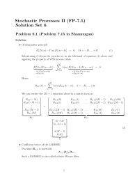
<strong>Voltmeter</strong> <strong>design</strong>As was stated earlier, most meter movements are sensitive devices. SomeD'Arsonval movements have full-scale deflection current ratings as little as 50 µA,with an (internal) wire resistance of less than 1000 Ω. This makes for a voltmeterwith a full-scale rating of only 50 millivolts (50 µA X 1000 Ω)! In order to buildvoltmeters with practical (higher voltage) scales from such sensitive movements,we need to find some way to reduce the measured quantity of voltage down to alevel the movement can handle.Let's start our example problems with a D'Arsonval meter movement having afull-scale deflection rating of 1 mA and a coil resistance of 500 Ω:Using Ohm's Law (E=IR), we can determine how much voltage will drive thismeter movement directly to full scale:E = I RE = (1 mA)(500 Ω)E = 0.5 voltsIf all we wanted was a meter that could measure 1/2 of a volt, the bare metermovement we have here would suffice. But to measure greater levels of voltage,something more is needed. To get an effective voltmeter meter range in excess of1/2 volt, we'll need to <strong>design</strong> a circuit allowing only a precise proportion ofmeasured voltage to drop across the meter movement. This will extend the metermovement's range to being able to measure higher voltages than before.Correspondingly, we will need to re-label the scale on the meter face to indicateits new measurement range with this proportioning circuit connected.
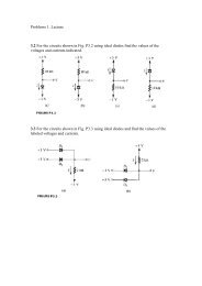
But how do we create the necessary proportioning circuit? Well, if our intention isto allow this meter movement to measure a greater voltage than it does now,what we need is a voltage divider circuit to proportion the total measured voltageinto a lesser fraction across the meter movement's connection points. Knowingthat voltage divider circuits are built from series resistances, we'll connect aresistor in series with the meter movement (using the movement's own internalresistance as the second resistance in the divider):The series resistor is called a "multiplier" resistor because it multiplies theworking range of the meter movement as it proportionately divides the measuredvoltage across it. Determining the required multiplier resistance value is an easytask if you're familiar with series circuit analysis.For example, let's determine the necessary multiplier value to make this 1 mA,500 Ω movement read exactly full-scale at an applied voltage of 10 volts. To dothis, we first need to set up an E/I/R table for the two series components:Knowing that the movement will be at full-scale with 1 mA of current goingthrough it, and that we want this to happen at an applied (total series circuit)voltage of 10 volts, we can fill in the table as such:There are a couple of ways to determine the resistance value of the multiplier.One way is to determine total circuit resistance using Ohm's Law in the "total"
column (R=E/I), then subtract the 500 Ω of the movement to arrive at the valuefor the multiplier:Another way to figure the same value of resistance would be to determine voltagedrop across the movement at full-scale deflection (E=IR), then subtract thatvoltage drop from the total to arrive at the voltage across the multiplier resistor.Finally, Ohm's Law could be used again to determine resistance (R=E/I) for themultiplier:Either way provides the same answer (9.5 kΩ), and one method could be used asverification for the other, to check accuracy of work.With exactly 10 volts applied between the meter test leads (from some battery orprecision power supply), there will be exactly 1 mA of current through the metermovement, as restricted by the "multiplier" resistor and the movement's owninternal resistance. Exactly 1/2 volt will be dropped across the resistance of the
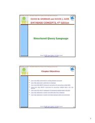
movement's wire coil, and the needle will be pointing precisely at full-scale.Having re-labeled the scale to read from 0 to 10 V (instead of 0 to 1 mA), anyoneviewing the scale will interpret its indication as ten volts. Please take note thatthe meter user does not have to be aware at all that the movement itself isactually measuring just a fraction of that ten volts from the external source. Allthat matters to the user is that the circuit as a whole functions to accuratelydisplay the total, applied voltage.This is how practical electrical meters are <strong>design</strong>ed and used: a sensitive metermovement is built to operate with as little voltage and current as possible formaximum sensitivity, then it is "fooled" by some sort of divider circuit built ofprecision resistors so that it indicates full-scale when a much larger voltage orcurrent is impressed on the circuit as a whole. We have examined the <strong>design</strong> of asimple voltmeter here. Ammeters follow the same general rule, except thatparallel-connected "shunt" resistors are used to create a current divider circuit asopposed to the series-connected voltage divider "multiplier" resistors used forvoltmeter <strong>design</strong>s.Generally, it is useful to have multiple ranges established for anelectromechanical meter such as this, allowing it to read a broad range ofvoltages with a single movement mechanism. This is accomplished through theuse of a multi-pole switch and several multiplier resistors, each one sized for aparticular voltage range:The five-position switch makes contact with only one resistor at a time. In thebottom (full clockwise) position, it makes contact with no resistor at all, providingan "off" setting. Each resistor is sized to provide a particular full-scale range forthe voltmeter, all based on the particular rating of the meter movement (1 mA,500 Ω). The end result is a voltmeter with four different full-scale ranges ofmeasurement. Of course, in order to make this work sensibly, the metermovement's scale must be equipped with labels appropriate for each range.
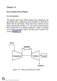
With such a meter <strong>design</strong>, each resistor value is determined by the sametechnique, using a known total voltage, movement full-scale deflection rating,and movement resistance. For a voltmeter with ranges of 1 volt, 10 volts, 100volts, and 1000 volts, the multiplier resistances would be as follows:Note the multiplier resistor values used for these ranges, and how odd they are.It is highly unlikely that a 999.5 kΩ precision resistor will ever be found in a partsbin, so voltmeter <strong>design</strong>ers often opt for a variation of the above <strong>design</strong> whichuses more common resistor values:With each successively higher voltage range, more multiplier resistors arepressed into service by the selector switch, making their series resistances addfor the necessary total. For example, with the range selector switch set to the1000 volt position, we need a total multiplier resistance value of 999.5 kΩ. Withthis meter <strong>design</strong>, that's exactly what we'll get:R Total = R 4 + R 3 + R 2 + R 1
R Total = 900 kΩ + 90 kΩ + 9 kΩ + 500 ΩR Total = 999.5 kΩThe advantage, of course, is that the individual multiplier resistor values are morecommon (900k, 90k, 9k) than some of the odd values in the first <strong>design</strong> (999.5k,99.5k, 9.5k). From the perspective of the meter user, however, there will be nodiscernible difference in function.• REVIEW:• Extended voltmeter ranges are created for sensitive meter movements byadding series "multiplier" resistors to the movement circuit, providing aprecise voltage division ratio.< BackForward >Kilde: http://www.allaboutcircuits.com/vol_1/chpt_8/3.htm den 5-9-05