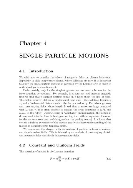
Chapter 4 SINGLE PARTICLE MOTIONS 4.1 Introduction
Chapter 4 SINGLE PARTICLE MOTIONS 4.1 Introduction
Chapter 4 SINGLE PARTICLE MOTIONS 4.1 Introduction

You also want an ePaper? Increase the reach of your titles
YUMPU automatically turns print PDFs into web optimized ePapers that Google loves.
4.3 Time Varying Fields 95analogously by translating to the frame moving with velocityto give (show this)v P = − m q= ± 1 ω cĖB˙v E ×BB 2(4.24)ddt [m(v c − v P )] = q(v c − v P )×B − qË . (4.25)The explicit E dependent term is now O(ω/ω c ) 2 and can be neglected. Theresidual equation for v c − v P describes the Larmor motion.Averaging the total motion over a gyro-period gives the overall guiding centredrift as 〈v〉 = v E +v P . The new polarization drift v P given by Eq. (4.24) (correctto first order in ω/ω c ) is charge dependent and points in the direction of E. Thepolarization current flow that results is given byj P = ne(v P i − v P e )= neeB (m 2 i + m e ) dEdt= ρ dEB 2 dt(4.26)where ρ = n(m i + m e ) is the plasma mass density. The polarization currentvanishes as ω/ω c → 0.ω 2 cAnalogy with solid dielectric polarizationFor a solid dielectric immersed in an electric field we construct the electric displacementvectorD = ε 0 E + P ≡ ε r ε 0 E (4.27)where P is the polarization vector due to the alignment of electric diploes andε r is the electric susceptibility. When the electric field varies with time, it drivesthe polarization current∂Ej P = ε r ε 0∂t . (4.28)Comparing with Eq. (4.26) we obtain an expression for the low-frequency plasmaelectric susceptibilityε r =≡ρε 0 B = µ 0 ρ2 ε 0 µ 0 B 2c2v 2 A(4.29)
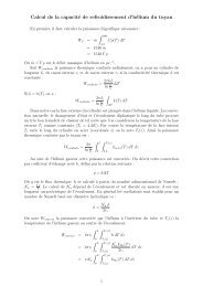
4.3 Time Varying Fields 97field E ⊥ as the sum of left and right hand circularly fields:E ⊥ = E L + E R (4.40)E L = 1 (E⊥ − i2)⊥ (4.41)E R = 1 ( )E⊥ +iˆB×E ⊥2(4.42)where ˆB ≡ ˆk. The imaginary term is the orthogonal electric field componentretarded or advanced in phase by 90 ◦ compared with E ⊥ as shown in Fig. 4.6.The linearly polarized field E ⊥ is equivalent to the sum of left and right circularlyFigure 4.6: The decomposition of E ⊥ into left and right handed components.polarized fields.To solve Eq. (4.38) we first note the result that BB ∗ is a scalar operator:BB ∗ v P ⊥≡(iω + q m B× )(−iω + q m B× )v P ⊥= ω 2 v P ⊥ + q2m B×B×v 2 P ⊥= (ω 2 − ωc 2 )v P ⊥. (4.43)
Materials, Trainings & Technical Assistancefor TreatmentSAMHSA’s Addiction Technology Transfer Centerswww.nattc.orgPurpose: To transmit the latest knowledge,skills and attitudes of professional addictiontreatment practice.Goal: To enhance clinical practice.
100than other plasma characteristic times such as the energy and particle confinementtimes. The radiative loss is also overestimated, since the radiation can bereabsorbed by the plasma. Indeed, the inverse process is used to provide resonantheating of the plasma as indicated by Eq. (4.54).Low frequency limitIt is instructive to show that the low-frequency polarization drift is recovered inthe limit ω/ω c ≪ 1. In this limit, the velocity is expressed by⎛⎜⎝This reduces tov xv yv z⎞⎟⎠ = ±iqmω⎛⎜⎝− ω2∓ iω ⎞0ωc2 ⎛ω c ± iω − ω2⎜0. ⎝ω c ωc2 ⎟⎠0 0 1E x00⎞⎟⎠ exp (−iωt). (4.58)v x = iq −ω 2Emω ωc2 x exp (−iωt)q ∂Ev x î =mωc2 ∂t= ± 1 ∂Eω c B ∂t(4.59)which is the same as Eq. (4.24) with the plus sign for ions and the minus forelectrons. What is the interpretation of the non-zero v y response to the field E x ?Plasma dielectric tensor (no collisions)We may also now derive an expression for the plasma dielectric tensor ↔ ε validat all frequencies (but without the effects of collisions - this is a single particlepicture!) by following the procedure used in the low frequency case. The dielectrictensor is extremely important to an understanding of wave propagation in aplasma.We start with Maxwell’s equation∇×B = µ 0()∂Ej + ε 0∂tConsidering the plasma as a dielectric, we write this as. (4.60)∇×B = µ 0∂D∂t(4.61)
4.3 Time Varying Fields 101withD = ε 0 E − 1iω j= ε 0 E − 1 ↔σ Eiω↔= ε 0 εr E≡ ↔ ε E (4.62)where↔ε= ε0( ↔I+iε 0 ω↔σ)(4.63)is the dielectric tensor, ↔ I is the unit tensor and the conductivity tensor is givenby Eq. (4.53). We can now derive the wave equation in a plasma:∇×E = − ∂B∂t∇× ⇒ ∇×∇×E = −µ 0↔ε Ë. (4.64)The solution is examined in later chapters.4.3.3 Slowly time varying magnetic fieldGenerally speaking, the magnetic field acts perpendicularly to the particle velocityand no work is done so that the change in kinetic energy of the particlemight be expected to be zero when the field strength changes. However, when∂B/∂t ≠ 0 there is an associated induced emf which acts on the particle orbit:∇×E = − ∂B∂t . (4.65)Assuming the rate of change of B is small compared with ω c [i.e.(1/B)(∂B/∂t) ≪ω c ] then the work done on the particle during a cycle can be evaluated over theunperturbed particle trajectory. Now work done equals change in kinetic energy,so∫δ(mv⊥/2) 2 = F.dl∮= q E.dl∫= q ∇×E.dS= −qS∫S∂B∂t .dS= |q | ∂B∂t πr2 L (4.66)
102BB.ds >0 electronsB.ds
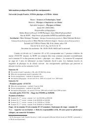
4.4 Inhomogeneous Fields 103where Φ is the magnetic flux linked by the particle orbit. Thus, if the magneticfield increases (decreases) slowly compared with ω c , the orbit radius decreases(increases) in such a way that the particle always encircles the same number ofmagnetic “lines of force”.4.4 Inhomogeneous Fields4.<strong>4.1</strong> Nonuniform magnetic fieldGrad B driftB∆|Β|-+yxzBFigure 4.8: The grad B drift is caused by the spatial inhomogeneity of B. It isin opposite directions for electrons and ions but of same magnitude.In this case we consider E = 0. As alluded in the introduction, we Taylorexpand the variation of B, B = bˆk, assuming that the variation in B across aLarmor orbit is small. This obtainsB = B 0 + y ∂B∂y+ ... (4.70)wherewehaveassumedthatB varies only in the y-direction and that the firstorder term is small. Since we consider variation in y of order the Larmor radiusr L ,werequirey < ∼ r L ≪ B/( ∂B∂y ) ∼ Lwhere L is the scale length for variation of B. Substituting into Eq. (4.3) andusing Eq. (<strong>4.1</strong>0) we obtainm ˙v y = −qv x B[= −qv ⊥ cos (ω c t) B 0 ± r L cos (ω c t) ∂B ]. (4.71)∂y
104Since the B-field is time invariant, we can average over a cyclotron period〈F y 〉 = 〈m ˙v y 〉 = ∓qv ⊥ r L∂B∂y 〈cos2 (ω c t)〉 (4.72)so that there is a residual y-force (but no x directed force - show this).resulting drift is given by Eq. (4.21)Thev ∇B = 1 F ×Bq B 2= 1 〈F y 〉Bîq B 2= ∓ v ⊥r L2BAlternatively, this can be expressed in vector formwhereB×∇B =∣∇B ≡∇|B|=î∂|B|∂xî ĵ ˆk0 0 B z0 ∂B∂y∂B î. (4.73)∂y0+ ĵ ∂ |B|∂y∣∂ |B|+ ˆk∂z .∇|B| often simplifies to ∇B z because B z ≫ B r ,B θ . The general result is(4.74)v ∇B = ± 1 2 v B×∇B⊥r L . (4.75)B 2The drift is in opposite directions for electrons and ions (see Fig. 4.8) but of thesame magnitude. The drift therefore results in a net current across B.Curvature driftIf the magnetic lines of force are curved, the charged particles feel a centrifugalforce proportional to the radius of curvature R c (see Fig. 4.9). The force felt isF c = mv2 ‖R cˆr = mv2 ‖ R cR 2 c(4.76)and the resulting drift can be written asv R = mv2 ‖qB 2 R c ×BR 2 c(4.77)
4.4 Inhomogeneous Fields 105r^F cθ^BR cFigure 4.9: The curvature drift arises due to the bending of lines of force. Againthis force depends on the sign of the charge.Combined grad B and curvature driftsConsider the ∇B drift that accompanies curvature in a cylindrical geometry:B = B θ =(B 0 /r)ˆθso∇B = ˆr ∂B 0/r= −ˆr(B 0 /r 2 )=−ˆrB θ /r = −r(B θ /r 2 )∂rwherewehaveused∇×B = 0 in vacuum andUsing Eq. (4.75) we have(∇×B) z = 1 r∂rB θ∂r⇒B θ ∼ 1 rv ∇B = ± 1 2 v B×∇B⊥r LB 2= ± 1 v⊥2 B×(−R c |B|)2 ω c B 2 Rc2= 1 mv⊥2 R c ×B(4.78)2 q RcB 2 2wherewehaveusedB/ω c = m/ |q|. Combining with the curvature drift we findv T = v ∇B + v R = m ( ) ( Rc ×Bv 2q RcB 2 2 ‖ + 1 )2 v2 ⊥ . (4.79)
106Figure <strong>4.1</strong>0: The grad B drift for a cylindrical field.Note that the two contributions add with similar magnitude because 〈v 2 ‖ 〉∼k B T/m and 1 2 〈v2 ⊥ 〉∼k BT/m.Magnetic mirrors — ∇B ‖ BWe have looked at particle drifts when ∇B is at an angle to B. What happenswhen the gradient is aligned with B? This situation is encountered in magneticmirrors where the magnetic field strength increases along the direction of thelines of force as shown in Fig. <strong>4.1</strong>1.Figure <strong>4.1</strong>1: Schematic diagram showing lines of force in a magnetic mirror device.We shall show that a charged particle inside such a magnetic topology canbe trapped under certain circumstances. Let’s describe mathematically the fieldstructure. The field must be divergence free (no sources or sinks): ∇.B =0. In
4.4 Inhomogeneous Fields 107cylindrical geometry this gives1 ∂rB rr ∂r+ ∂B z∂zProvided ∂B z /∂z does not vary much with r we have∫ rrB r = −0=0. (4.80)r ∂B z ∂B zdr ≈−r2∂z 2 ∂z(4.81)orB r = − r ∂B z2 ∂z . (4.82)Any radial inhomogeneity of B r gives an azimuthal drift B z ˆk×∇Brˆr about theaxis of symmetry [see Fig. <strong>4.1</strong>1] but there is no radial drift (why?).What is the effect of the Lorentz force in the cylindrical field?F = qv×B =∣∣ˆr ˆθ ẑ ∣∣∣∣∣∣v r v θ v zB r 0 B z= ˆr(qv θ B z ) − ˆθq(v r B z − v z B r ) − ẑ(qv θ B r ). (4.83)For simplicity, consider a particle spiralling along the axis (r = r L )sothatwecan ignore grad B drifts. The logitudinal (axial) force isq ∂B zF z = v θ r L2 ∂z= ∓v ⊥ r Lq2∂B z∂z= ∓ qv2 ⊥ ∂B z2ω c ∂zions and electrons= − mv2 ⊥2B ∇ ‖Bwhere v ⊥ is the cyclotron speed. Expressed in terms of the magnetic moment,F ‖ = −µ∇ ‖ B. (4.84)This force is away from increasing B and is equal for particles of equal energy(independent of charge).A particle moving from a weak field region to a strong field sees a time changingmagnetic field. However, the magnetic moment stays constant during thismotion provided the rate of change is slow. Since µ is a constant of the motion,thenv 2 ⊥0B 0= v2 ⊥mB m(4.85)
108where the subscript 0 refers to the low field conditions and subscript m is forthe high field “mirror” region. Thus if B m >B 0 then v ⊥m >v ⊥0 . However, theB-field does no work so that the total particle kinetic energy remains unchanged:K = m(v‖ 2 0+ v⊥0 2 )/2 is constant. Therefore, we must have v ‖m
4.4 Inhomogeneous Fields 109Figure <strong>4.1</strong>2: Top:The flux linked by the particle orbit remains constant as theparticle moves into regions of higher field. The particle is reflected at the pointwhere v ‖ = 0. Bottom: Showing plasma confined by magnetic mirrorwhere the drift is up or down for electrons or ions (see Fig. <strong>4.1</strong>0). We thus obtainv Tv th∼ ±r LR c≡ κ. (4.90)For H-1NF, κ ≈ 1 × 10 −3 (drift angle to field line) so that the toroidal traveldistance for a particle to drift out of the magnetic volume is d T =0.1m/κ = 100m which is about 16 toroidal orbits.As already noted, the electrons and ions drift in opposite directions. Thisgenerates a vertical electric field as shown in Fig. <strong>4.1</strong>4. The resulting E×B driftpushes the plasma to the wall and the plasma is not confined.This problem can be remedied by twisting the field lines (by introducinga toroidal current). Particles moving freely along B will then short out the
110θ mv zvv ⊥v yv xFigure <strong>4.1</strong>3: Particles having velocities in the loss cone are preferentially lostpotential difference. Another way of thinking of this is to note that at the top ofthe torus the particle is drifting out, while at the bottom, it is drifting inwards.These two drifts compensate. The helicity of the lines of force is called therotational transform and is shown in Fig. <strong>4.1</strong>54.4.3 Particle orbits in a tokamak fieldThe toroidal magnetic field in a tokamak varies inversely with major radius. Tosee this, let us apply Ampere’s law around a closed circular loop threading thetorus. We assume this imaginary loop encloses N toroidal field coils each carryingcurrent I in the same direction. We then have∮B.dl = 2πRB = µ 0 NI
4.4 Inhomogeneous Fields 111Figure <strong>4.1</strong>4: The grad B drift separates vertically the electrons and ions. Theresulting electric field and E/B drift pushes the plasma outwards.Figure <strong>4.1</strong>5: A helical twist (rotational transform) of the toroidal lines of forceis introduced with the induction of toroidal current in the tokamak. Electronsfollow the magnetic lines toroidally and short out the charge separation causedby the grad B drift.B = µ 0NI2πR . (4.91)
112To first order in ɛ = r/R 0 ,whereR 0 is the radius of the magnetic axis, the fieldstrength at some point in the torus is (show this)B = B 0 (1 − ɛ cos θ) (4.92)where θ is the poloidal angle coordinate with respect to the magnetic axis and B 0is the magnetic field strength on axis. (See Fig. <strong>4.1</strong>6 for the coordinate systemused here).If we now follow an electron along a helical field line, then if it starts at theoutside of the torus and moves towards the torus axis (inside), the magnetic fieldincreases. As a result, some of the electrons will be reflected (at points P and QFigure <strong>4.1</strong>6: Diagram showing toridal magnetic geometryin Fig. <strong>4.1</strong>7) by the mirror effect. The projection of the guiding centre drift ontothe R–z plane shows a banana-shaped orbit. Between the reflection points thereis an upward drift due to curvature and ∇B. Typically, the banana width fora tokamak < ∼ 0.1a where a is the minor radius. Particles with sufficiently highparallel velocity will penetrate the magnetic well and complete a toroidal circuit.These are called passing particles.
4.4 Inhomogeneous Fields 113Passing orbitsAs the particle moves freely toroidally, its orbit projected onto the R-z (poloidal)plane is given bydxdt = −Ωz dzdt =Ωx + v z (4.93)wherewehavetakenx = R − R 0 and where the vertical z drift velocity is givenbyv z =m2qB φ R (2v2 ‖ + v2 ⊥ ). (4.94)In Eq. (4.93) Ω = dθ/dt is the angular velocity of the particle orbit projectedonto the poloidal plane (imagine the torus straightened into a cylinder and lookingalong the axis of the helical magnetic field line). The rotation in this plane arisesfrom the helicity of the magnetic field line. The rate of spiralling of the field lineis given byrdθB θ= RdφB 0and is characterised by the so-called winding number or safety factor q(r) whichis defined byq(r) = dφdθ = rB 0= ɛ B 0. (4.95)RB θ B θIn tokamaks, q typically lies in the range 0.7
114This shift is shown in Fig. <strong>4.1</strong>7=( ) vthq(r)ω c= q(r)r L . (4.97)Trapped particlesLet’s now assume that (v ⊥ /v ‖ ) 2 > 1/ɛ so that particles are trapped and bouncein the mirrors produced by the 1/R variation of the toroidal field.We wish to find a relationship between the radial motion of trapped particlesand their parallel velocity. Geometry tells that the radial component of thevertical drift velocity isv r = v z sin θ= mv2 ⊥2qB 0 R sin θ (for v2 ‖ ≪ v⊥). 2 (4.98)The parallel force felt by the particle due to the increasing toroidal field ismv ˙ ‖ = −µ ∂B∂l(4.99)where l ≈ Rφ is the distance coordinate along the magnetic field line. Thecoordinate l is related to the poloidal angle θ through the safety factor q:l ≈ Rφ = rB 0θB θorθ = κl with κ ≡ B θrB 0where r is the radius of the field line with respect to the magnetic axis. The rightside of Eq. (4.99) can now be evaluated as∂B∂l= ∂ ∂l [B 0(1 − ɛ cos κl)]= B 0 ɛκ sin κl=r B θB 0 sin θR 0 rB 0= B θsin θR 0(<strong>4.1</strong>00)where we have used Eq. (4.92). Equation (4.99) now givesv ˙ ‖ = − mv2 ⊥2B 0= − v2 ⊥2B θsin θmR 0B θsin θ. (<strong>4.1</strong>01)R 0 B 0
4.4 Inhomogeneous Fields 115Comparing with Eq. (4.98) we obtainv r = − mqB θ˙ v ‖which integrates to giver − r 0 = − m v ‖ (<strong>4.1</strong>02)qB θwhere r 0 is the turning point at which v ‖ = 0. Equation (<strong>4.1</strong>02) describesthe poloidal projection of the banana orbit. To obtain the orbit width, we useEq. (4.86) with K ≈ mv⊥/2 2 to obtain for the change in v ‖ around the orbitδv ‖ =[ 2m (K − µB) ] 1/2≈ v ⊥ ɛ 1/2 (<strong>4.1</strong>03)where we have substituted from Eq. (4.92) for B. Alsonotethatso that Eq. (<strong>4.1</strong>02) becomesω cθ = qB θm ≈ɛ qB 0q(r) m= ɛω cq(r)(<strong>4.1</strong>04)δr = δv ‖ω cθ≈ q(r)r L /ɛ 1/2 . (<strong>4.1</strong>05)The width of the banana orbit is bigger again by the factor ɛ −1/2 than thepassing particles. This has profound consequences, with neoclassical diffusionincreased again over the cylindrical value.ProblemsProblem <strong>4.1</strong> The polarization drift v P can also be derived from energy conservation.If E is oscillating, the E×B drift also oscillates, and there is an energy 1 2 mv2 Eassociated with the guiding centre motion. Since energy can be gained from an Efield only be motion along E, there must be a drift v P in the E direction. By equatingthe rate of change of energy gain from v P .E, find the required value of v P .HINT: v P and E are in quadrature.Problem 4.2 A1keVprotonwithv ‖ =0in a uniform magnetic field B =0.1Tis accelerated as B is slowly increased to 1T. It then makes an elastic collision witha heavy particle and changes direction so that v ‖ = v ⊥ . The B field is then slowlydecreased back to 0.1 T. What is the proton energy now?
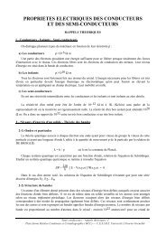
116∆Flux surfacePassingTrappedFigure <strong>4.1</strong>7: Top: Schematic diagram of trajectory of “banana orbit” in a tokamakfield. Bottom: The projection of passing and banana-trapped orbits ontothe poloidal plane.
4.4 Inhomogeneous Fields 117Problem 4.3 Consider the magnetic mirror system shown below. Suppose that theaxial magnetic field is given byB(z) =B 0 [1 + (z/a) 2 ]where B 0 and a 0 are positive constants and that the mirroring planes are at z = ±z m .(a) For a charged particle just trapped in this system, show that the z component ofthe particle velocity is given byv ‖ (z) = { (2µB 0 /m)[(z m /a) 2 − (z/a 0 ) 2 ] } 1/2(b) The average force acting on the particle guiding centre along the z axis is givenby〈F ‖ 〉 = −µ ∂B∂z ẑShow that the particle executes a simple harmonic motion between the mirroringplanes with a period given by.T =2πa 0 [m/(2µB 0 )] 1/2Problem 4.4 A plasma with an isotropic velocity distribution is placed in a magneticmirror trap with a mirror ratio R m =4. There are no collisions so that the particles inthe loss cone simply escape and the rest remain trapped. What fraction is trapped?Problem 4.5 Consider the motion of an electron in the presence of a uniform magnetostaticfield B = B 0 ẑ, and an electric field that oscillates in time at the electroncyclotron frequency ω c according toE(t) =E 0 [ˆx cos(ω c t)+ŷ sin(ω c t)](a) What type of polarization has this electric field?(b) Obtain the following uncoupled differential equations satisfied by the velocitycomponents v x (t) and v y (t):d 2 v xdt + 2 ω2 c v x =2(eE 0 /m)ω c sin(ω c t)d 2 v ydt + 2 ω2 c v y = −2(eE 0 /m)ω c cos(ω c t)
118(c) Assume that at t =0, the electron is located at the origin of the coordinatesystem with zero velocity. Neglect the time varying par of B. Verify that theelectron velocity is given byv x (t) =−(eE 0 /m)t cos(ω c t)v y (t) =−(eE 0 /m)t sin(ω c t)and that its trajectory is given byx(t) =−(eE 0 /m)[(1/ωc)cos(ω 2 c t)+(t/ω c )sin(ω c t) − 1/ωc]2y(t) =−(eE 0 /m)[(1/ωc 2 )sin(ω ct) − (t/ω c )cos(ω c t)]