
Create successful ePaper yourself
Turn your PDF publications into a flip-book with our unique Google optimized e-Paper software.
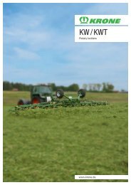
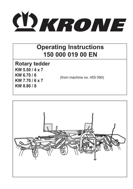
Rotary tedderKW 5.50 / 4 x 7KW 6.70 / 6KW 7.70 / 6 x 7KW 8.80 / 8<strong>Operating</strong> <strong>Instructions</strong><strong>150</strong> <strong><strong>00</strong>0</strong> <strong>019</strong> <strong>00</strong> <strong>EN</strong>(from machine no. 455 090)KRONEKRONE
EC Declaration of Conformitycorresponding to the EC Directive 98/37/ECWeMaschinenfabriken Bernard Krone GmbHHeinrich-Krone-Str. 10, D-48480 Spelledeclare in our sole responsibility that the productKrone Rotary tedderType: KW 5.50/4x7; KW 6.70/6; KW 7.70/6x7; KW 8.80/8to which this declaration refers corresponds to the relevant basic safety and health requirements ofthe EC Directive 98/37/EC.Spelle, 02.05.2<strong>00</strong>5(Dr.-Ing. Josef Horstmann, Managing Director)(ppa. Dr.-Ing. Klaus Martensen, Manager of the engineering and design dep.)Dear customer,You have now received an operating manual for the KRONEproduct which you have purchased.This operating manual contains important information for the properuse and safe operation of the machine.If this operating manual should for any reason become wholly orpartially unusable, you can obtain a replacement operatingmanual for your machine by stating the number given on theother side.
I. ForewordDear customer,Ordering Replacement PartsWe thank you for the trust you have placed in us bypurchasing this machine.When you received this machine, the dealer shouldhave given you instructions for the operation,maintenance and adjustment of the machine.However, this brief introduction to the machine cannot replace a detailed acquaintance with the differenttasks and functions of the machine and the proper wayof treating it.These operating instructions are designed so that youare extensively informed of the activities required ineach area, from commissioning and operation to themaintenance and care of the machine. The structure ofthe individual chapters in the text and illustrationscorresponds to the sequence of work procedures whenyou use the machine.Read these operating instructions carefully before youuse the machine, and pay special attention to thesafety instructions.Important: To avoid accidents and to ensuremaximum results, no alterations maybe made to the machine without themanufacturer´s permission. Similarly,the machine must only be used underthe conditions prescribed by Krone.JahrAnnéeTypeMaschinenfabrik Bernard Krone GmbHHeinrich-Krone-Straße 10, D 48480 SpelleMasch. NrNo. de sérieMade inGermanyKW-1-<strong>00</strong>2This symbol is designed to draw attentionto the safety instructions contained in theoperating instructions. These instructionsmust be observed to prevent accidents.You will find this symbol at various pointsin the operating instructions. It givesspecial handling instructions whichshould be particularly observed in the useof the machine.All information, illustrations and technical information inthe operating instructions represent the latest status atthe date of publication. The company reserves the rightto make constructional alterations at any time andwithout prior notice or obligation.TypeMach. No.YearWhen ordering replacement parts, the machine type,machine number and year of manufacture must begiven. These details can be found on the identificationlabel on the machine.We recommend that these details be entered in theabove boxes so that they are readily available.And please remember that imitations and copies ofparts, especially wearing parts, do not keep what theyappear to promise. Material quality is difficult to testvisually, therefore special care is required whenpurchasing cheap offers and imitation parts!The simplest remedy:Purchase only original KRONE parts!1
IIList of contentsI Foreword ........................................................................................................................ 1II List of contents ............................................................................................................. 2III General ........................................................................................................................... 31. Introduction1.1 Position of the warning signs, with safety-technical information, on the machine ........... 61.2 Position of the general information labels on the machine .............................................. 81.3 Technical data ................................................................................................................. 102. Preparations for use2.1 Special safety instructions ............................................................................................... 112.2 Preparations on the tractor and rotary tedder ................................................................. 112.3 Attaching the rotary tedder to the tractor ......................................................................... 122.4 Adapting the PTO shaft length ........................................................................................ 152.5 Lighting ........................................................................................................................... 152.6 Warning and protection features ..................................................................................... 162.7 Working position.............................................................................................................. 162.8 Transport position ............................................................................................................ 172.9 Disassembly of the rotary tedder .................................................................................... 183. Settings3.1 Special safety instructions ............................................................................................... 203.2 Spreading angle settings for the swather discs ............................................................... 203.3 Adapting the swather discs to the ground ....................................................................... 213.4 Edge spreading mechanism............................................................................................ 213.5 Stabilizers........................................................................................................................ 223.6 Tine adjustment............................................................................................................... 234. Care and maintenance4.1 Special safety instructions ............................................................................................... 244.2 General ........................................................................................................................... 244.3 Hydraulics ....................................................................................................................... 254.4 Gearbox .......................................................................................................................... 254.5 Tyres................................................................................................................................ 254.6 Lubrication points on the individual rotary tedders .......................................................... 255. Winter storage5.1 Safety instructions ........................................................................................................... 295.2 General ........................................................................................................................... 296. Start-up after winter storage ........................................................................................ 306.1 Vent Overload Coupling on the PTO Shaft ...................................................................... 307. Special accessories7.1 Night swathing gearbox ................................................................................................... 317.2 Additional tine loss safety mechanism ............................................................................ 327.3 Wheel guards .................................................................................................................. 337.4 Fixed lighting ................................................................................................................... 352Appendix to the operating manual (assembly instructions) ..................................... 36
III. General1. Operation in Accordance withSpecificationsThe rotary tedder is designed solely for normal agriculturaluse (operation in accordance with specifications).Any use of the machine for other purposes is deemed tobe not in accordance with specifications. The manufacturerbears no responsibility for any resulting damage; such useis entirely at the operator´s risk.Use in accordance with specifications also includesadherence to the operating, maintenance and serviceinstructions prescribed by the manufacturer.The rotary tedder must only be used, maintained andrepaired by personnel who are acquainted with the machineand have been informed of the danger involved.The applicable accident prevention regulations and allother generally recognized safety, health and road trafficregulations must be adhered to.Any unauthorized alterations to the machine render anyliability for damage undertaken by the manufacturer nulland void.Basic rule:Before any public roads are used andbefore the machine is started, check therotary tedder and the tractor for roadworthinessand operational safety.2. Safety and Accident PreventionRegulations1. Take note of both the regulations in these operatinginstructions and also the general safety and accidentprevention regulations!2. The attached warning and information signs giveimportant advice for safe operation. Observing themwill enhance your safety!3. When you use public roads, make sure you observethe relevant traffic regulations!4. Make sure you know all equipment and controls beforeyou begin working with the machine. When you areoperating the machine, it´s too late!5. The operator´s clothing should be tight fitting. Avoidwearing loose fitting clothes.6. Keep the machine clean to prevent the danger of fire!7. Before starting the machine and moving off, check thedanger area around the tractor (children!). Good visibilityis absolutely essential!8. Carrying passengers on the implement during work ortransport is not permitted.9. Make sure that the implement is correctly coupled, andthat it is only fixed and secured with the prescribedfittings!10.Make sure that the supporting devices, jacks etc. arein the correct position during assembly and removal!11.Special care is required when equipment is beingcoupled to the tractor or detached from the tractor!12.Ballast weights must always be attached in theprescribed way at the designed attachment points!13.Adhere to the permitted axle loads, total weights andtransport dimensions!14.Check and fit transport equipment – e.g. lighting,warning signs and, if required, protective equipment!15.<strong>Operating</strong> equipment for remote controls (ropes, chains,rods etc.) must be laid out in such a way that, whateverthe working or transport position, it can not inadvertentlycause any movements.16.Prepare equipment for road transport as prescribed bythe manufacturer, and lock the equipment in accordancewith the manufacturer's regulations!17.Never leave the driver´s position when the tractor is inmotion!18.The speed of travel must always be suited to theenvironmental conditions! Avoid any sudden turnswhen travelling uphill, downhill or across a slope!19.The handling, steering and braking of the tractor isaffected by integrated or attached equipment andballast weights. Make sure that you allow for moreflexibility in steering and braking!20.When turning, remember to take account of the wideload and/or the greater weight of the equipment!21.Only switch on equipment when all protectivedevices are fitted and in protection position!3
22.Persons are not allowed to enter the working area!23.Keep clear of the area of rotation and swing of theequipment!24.Hydraulic controls must only be operated if no personsare in the swing area!25.Power operated parts (e.g. by hydraulics) containdanger points which can cause injury by bruising andgrazing!26.Before leaving the tractor, rest the machine on the,ground, switch off the engine and remove the ignitionkey!27.Make sure that no personnel go between the tractorand the implement unless the tractor is protected fromrolling by the parking brake and/or wheel blocks!3. Attached Equipment1. Special care is required when the implements isbeing connected to the tractor or disconnected fromit!2. The implement must only be coupled to theappropriate fittings (e.g. the 3-point connection), andthey must be so secured (transport, operation) thatunintentional lifting or lowering of the implement isnot possible.3. When connecting the three point linkage, it isabsolutely essential that the hitching categories ofthe tractor and attachment (e.g. power take-off shaftspeed, hydraulics) are matched!4. When operating the external controls for three-pointconnection, make sure that nobody goes betweenthe tractor and the implement (danger of injury)!4. Power Take-Off shaft Operation1. Only the P.T.O. shafts prescribed by the manufacturermay be used!2. Both male and female guard tubes and cones of allP.T.O. shafts must be fitted and in good condition!3. Observe the tube overlap prescribed for P.T.O. shaftsin transport and operating position!5.When using P.T.O. shafts with overload or free wheelclutches that are not covered by the guards on thetractor, the overload or free wheel clutches must befixed on the implement side!6. Always ensure correct assembly and guarding of theP.T.O. shaft!7. Protect the P.T.O. shaft guard from rotating with theshaft by fitting the chains!8. Before switching on the power take-off shaft, makesure that the p.t.o. speed of the tractor matches thepermitted speed of the implement!9. Before switching on the power take-off shaft, makesure that nobody is in the danger area of the implement!10.Never switch on the power take off shaft when thetractor engine is turned off!11.Any work on the power take-off shaft may only becarried out when nobody is in the area of the rotatingpower take-off shaft or P.T.O. shaft.12.The power take-off shaft should always be turned offwhen the angle is too great or the p.t.o. shaft is notrequired!13.Danger! Working elements continue to rotate after thepower take-off shaft is turned off! Do not approach themachine during this time! Work may only be carried outon the machine when the machine is fully stationaryand the rotating parts have been secured.14.Cleaning, lubrication or adjustment of the P.T.O. shaftor any equipment driven by the power take-off shaftmay only be carried out when the p.t.o. shaft and theengine are turned off and the ignition key has beenremoved! Rotating parts must be secured with theparking brake.15.Place the detached P.T.O. shaft on the support bracketprovided!16.After removing the P.T.O. shaft, place the protectivecover on the stub of the power take-off shaft!17.Any damage must be repaired immediately before anywork is carried out with the attachment!4. Before installing or removing the P.T.O. shafts, makesure to turn off the power take-off shaft and the engine,and remove the ignition key!4
5. Hydraulic System1. The hydraulic system is pressurized!2. When connecting hydraulic cylinders and motors,make sure that the hydraulic hoses are correctlycoupled!3. When connecting hydraulic hoses to the tractor´shydraulic system, make sure that all pressure hasbeen released from the hydraulics of both thetractor and the implement!4. When there are functional hydraulic connectionsbetween the machine and the implement, allcoupling sleeves and plugs must be marked toprevent operating errors. If the connections areswitched, the functions are reversed (e.g. liftingand lowering) – this can cause accidents!5. Hydraulic hoses must be checked regularly, andthey must be replaced if they are damaged orworn. Replacement hoses must conform to thetechnical requirements of the implementmanufacturer!6. When tracing leaks, suitable aids should be usedto prevent injury!7. Fluid leaking under high pressure (hydraulic oil)can penetrate the skin and cause serious injury!When injury occurs, consult a doctor immediately!Danger of infection!8. Before carrying out any work on the hydraulicsystems, lower the machine to the ground,depressurize the system and turn off the engine!6. Maintenance1. Repair, maintenance and cleaning work and thecorrection of malfunctions must always be carried outonly when the drive is turned off and the engine is ata standstill! Remove the ignition key! Apply the parkingbrake.2. Nuts and bolts must be checked regularly for tightness,and tightened if necessary!3. When carrying out maintenance work on the machinein a lifted position, it must always be supported onsuitable jacks.4. When replacing fittings that contain cutting blades,always use suitable tools and gloves!5. Oil, grease and filters must be correctly disposedof!6. The power supply must always be disconnectedbefore any work is carried out on the electrical system!7. If protective devices are subject to wear, they must bechecked regularly and replaced in good time!8. When electric welding is carried out on the tractor andany fitted attachments, the cables must be disconnectedfrom the generator and battery!9. Replacement parts must conform at least to thetechnical requirements defined by the manufacturer!The best guarantee is to use only original KRONEparts!10.Where gases are stored, only refill with nitrogen.Danger of explosion!5
1. IntroductionThe KRONE rotary tedder is equipped with all necessary safety features (protective devices). Not all danger pointson this machine can be completely secured with regard to the preserving of the function of the machine. Themachine bears appropriate warning labels to point out these residual dangers.We have designed these danger notices in the form of so-called warning symbols. This chapter contains importantinformation on the position of these warning labels and their meaning/explanation!Make sure that you are fully conversant with the meaning of the warning symbols opposite.The text next to the symbols and the position of the signs on the machine give informationabout the specific danger points on the machine.1.1 Position of the warning signs, with safety-technical information, on the machine35334 3 6 2 1 6 4re + liKZW-1-<strong>00</strong>16
1Do not exceed themaximum permittedPTO shaft speed!Order No. 939 1<strong>00</strong>-4 (1x)939 1<strong>00</strong>-4MAX. 540/minMAX. 2<strong>00</strong> bar2Read and take note of theoperating manual.Order No. 939 471-1 (1x)34Danger from self-turning swather disk arms.Maintain safe distance!Order No. 939 472-2 (4x)No personnel allowed inside swivel space ofthe operating equipment while the deploymentarms are being folded down.Order No. 939 469-1 (2x)56Accumulator is under gas and oil pressure.Repairs can be carried out only in connectionwith replacement of the complete unit.Order No. 939 529-0 (1x)Never reach into thedanger zone between thethree-point frame and thecarrier bar of the rotarytedder while any partslocated there can stillmove by themselves.Order No. 942 196-1 (2x)7
1.2 Location of General Information Labels on the Machine122 13 1 2 10 3 211111158 4 675KZW-1-<strong>00</strong>18
1440 135-3 (1x) bei KW 5.50939 429-2 (1x) bei KW 6.70440 148-2 (1x) bei KW 7.70942 273-1 (1x) bei KW 8.802942 295-0 5<strong>00</strong> lang942 296-0 370 lang942 297-0 2<strong>00</strong> lang grün942 298-0 2<strong>00</strong> lang beige3 942 103-1 (1x)85 Nm72 Nm20h42 Nm942 067-14 942 085-0 (1x) 5 942 067-0 (2x)6 942 118-0 (1x)7 939 138-2 (3x) 8 939 139-1 (3x) 9 939 278-1 (1x)KW 7.70 ; KW 8.80Traktor-Steuerventil - Schwimmstellung942 302-0TransportService1,5 barVanne-pilote du tracteur - position flottanteTractor operation valve - float positionValvola di comando del trattore - flotante939 172-310939 172-3 (only KW 8.80)11 942 107-1 1,5 bar12 942 302-0 (1x)939 170-1 2,0 baronly KW 8.8013924 569-0 (4x) KW 5.50/ KW 6.70 / KW 7.70 / KW 8.80924 573-0 (1x) KW 6.70 / KW 7.70 / KW 8.80924 574-0 (1x) KW 6.70 / KW 7.70 / KW 8.809
1.3 Technical dataType KW 550/4x7 KW 670/6 KW 770/6x7KW 880/8Working width [mm] 55<strong>00</strong> 67<strong>00</strong> 77<strong>00</strong> 88<strong>00</strong>Number of swather discs 4 6 6 8Tine arms per swather disc 7 6 7 6Surface covered [appr. ha/hr] 5.5 6.7 7.7 8.8Width in transport position [mm] 2930 2950 2980 2980Height in transport position [mm] 28<strong>00</strong> 3250 35<strong>00</strong> 3450Power consumption [KW/HP] 37/50 37/50 44/60 55/75Max. allowable hydraulic pressure2<strong>00</strong> barPto shaft speed [max. rpm] 540 540 540 540Weight [kg] 640 8<strong>00</strong> 890 11<strong>00</strong>Equivalent continuous sound pressure levelunder 70 d B(A)Tyres for all types, 16/ 6.50 x 8 18/8.50/8only middleThree-point mounting with quick coupler andrun-on mechanismEdge spreading mechanism [hydr.]Spreading angle adjustmenAdditional tine loss protectionPlug-in gearbox for night swathingLighting unitStandard equipmentStandard equipmentStandard equipmentSpecial accessorySpecial accessory12 VoltLubricant quantities and lubricant types for the gearboxThe main gearbox of the rotary tedder has a permanent grease lubrication and operates without anymaintenance.10
2. Preparations for use2.1. Special safety instructions• In all care, maintenance, repair and assembly work on the rotary tedder the PTO shaft mustalways be switched off. Switch off the engine and remove the ignition key. Take measuresto prevent the tractor and rotary tedder from rolling!• The maximum drive speed is 540 rpm.• Control elements such as ropes, cables, hydraulic hoses and electrical cables must be sorouted that accidental activation and contact with the tractor wheels are impossible.Accident risk!• When raising and lowering the rotary tedder, no persons may be allowed to go between thetractor and the rotary tedder. High risk of injury!• When lowering the outer swather discs, make sure that no persons are in the swivel area ofthe swather discs Accident risk!• Before you switch on the PTO shaft, make sure that no persons are in the danger zone ofthe rotary tedder. Accident risk!• Make sure that the protective features are correctly fitted during operation and when drivingthe tractor on public roads. Fit the lighting and check that it works.• The operating personnel must not leave the tractor when the rotary tedder is in operation!Safety instructions for the hydraulic system• The hydraulic system is under pressure!• Hydraulic oil that squirts out under high pressure can cause severe injury. Consult a doctorimmediately if such injuries occur. Risk of infection!• Check hydraulic hoses and pipes regularly, and replace them if they are damaged or worn.The replacement hoses and pipes must conform to the requirements of the manufacturer ofthe machine!• When connecting hydraulic hoses, take care to ensure that the hydraulic system in both thetractor and the attachment is depressurized.2.2. Preparations on the tractor and rotary tedderWhen fitting the bracket to the tractor,make sure that the switchover valve iseasily accessible and the hydraulichoses (3) do not obstruct the driver.Hose lines may must not be placed inthe cabin.2 3Fix the bracket (1) for the hydraulic switchover valve (2)to the tractor. Make sure that the hydraulic hoses arenot pulled tight or trapped when the attachment israised and lowered.1KW-0-<strong>00</strong>311
Mounting the PTO shaft on the rotarytedderKW 5.50 / 4x7 and KW 6.70 / 612Only those PTO shafts provided may bemounted and used.To mount the PTO shaft on the rotary tedder, unscrewthe screw (1) on the rotary shaft protective sleeve (2),twist the protective socket and the protective tubeagainst each other and push the PTO shaft protectivesleeve in the direction of the arrow.Push the PTO shaft with the overload clutch onto thePTO shaft end on the rotary tedder. Take care toensure that the locking device (1) clicks into place. Fitthe protective sleeve again and secure it with a screw.Note direction of arrow on PTO shaft!KW-0-0381KW 7.70 / 6x7 and KW 8.80 / 8The PTO shaft is fitted with the friction/free runningcoupling facing the rotary tedder. The disassembly ofthe PTO shaft protective sleeve is not necessary here.Make sure that the locking device clicks into place.Vent the overload coupling beforecommissioning.(see chapter 6.1)KW-0-0392.3 Attaching the rotary tedder to thetractor• When fitting the rotary tedder, makesure that nobody enters the areabetween the implement and thetractor.• Make sure that the tractor frontwheels remain on the ground whenthe rotary tedder is raised. Ifnecessary, raise the ballast on thefront axle.2Couple the rotary tedder to the lower link arm (1) andupper link arm (2). Fix the lower link arms to the tractoruse limiting chains or rods so that the rotary tedderdoes not swivel out to the side.1KW-0-<strong>00</strong>8The withdrawal speed of the rearhydraulic system must be reduced byadjusting the lowering throttle so thatthe undercarriage of the rotary tedder isslowly lowered to the ground.12
PTO shaftAfter the rotary tedder has been coupledto the upper and lower link arm, turn offthe engine. Remove the ignition key.Protect the tractor from rolling!Push the PTO shaft onto the PTO shaft end of thetractor. Make sure that the locking device clicks intoplace. Fix the protective sleeve (1) with chains (2) toprevent it from rotating with the shaft.Check the PTO shaft for correct lengththe first time the rotary tedder is usedand every time a different tractor is used.If the length of the PTO shaft is notcorrect for the tractor, it is essential totake note of section 2.4 "Adjusting thePTO shaft length".21412KW-0-<strong>00</strong>9Hydraulics3Make sure that the hydraulic system isdepressureized in the tractor and in therotary tedder attachment.KW 5.50/4x7; KW 6.70/6 and KW 7.70/6x7Take the hydraulic switchover valve (1) out of thebracket (4) and insert it into the holder on the tractor.Take the hydraulic hose (2) out of the bracket (3) andinsert it into the coupling of a single action control valve.2KW-0-010KW 8.80/8Insert the hydraulic hoseinto the coupling of a doubleaction control valve.Transport locking deviceKW 5.50/4x7; KW 6.70/6 and KW 7.70/6x7The rotary tedder is equipped with a mechanical lockingdevice.Fix the control cable to the tractor. Make sure that thecable does not come into contact with the tractorwheels.Make sure that the transport lockingdevice is always correctly engagedwhen the machine is in transportposition.1KW-0-05113
KW 8.80/8The swather disk arms are secured intransport position with hydraulic stopvalves on the hydraulic cylinders. In casesof transport journeys, the shut-off valve (1)must be closed and the tractor controlvalve must be locked!1KW-4-<strong>00</strong>1Before raising the rear hydraulics, makesure that the rear window of the tractorcabin is closed. Otherwise, theprotective frame of the rotary teddercould cause damage.KW-0-011Jack standJack stand at frontTherotary tedders is fitted with a jack stand that foldsaway to the rear (1). The jack stand is folded away inworking position. To do this, lift the rotary tedder slightlyand remove the linch pin (2). Fold the jack up toposition "3" and secure it with a linch pin (2).321KW-1-016Jack stand at rearThe rotary tedders KW 460, KW 550, KW 670 and KW770 are fitted with a jack stand (2) at the rear. Inworking position, fold up the jack stand and secure it inposition "3" with a linch pin (1).13The rear jack stand (2) mainly preventsthe rotary tedder from tipping overbackwards when it is stopped while inoperating position. - Danger ofaccident!2KW-0-05314
2.4 Adjusting the PTO shaft length• Risk of damage to material. Do not raise the rotary tedder before the length of the PTOshaft has been adapted!• The PTO shaft must be switched off before any, maintenance, repair and assembly work iscarried out on the rotary tedder. Switch off the engine and remove the ignition key. Securethe tractor and rotary tedder to prevent them from rolling!• When raising the rotary tedder, no persons must be allowed to enter the area between therotary tedder and the tractor.• Take apart the universal drive shaft.• Clip one half (1) and (2) onto the tractor andthe other to the implement.• Move the rotary tedder to the position where theuniversal drive shaft is at its shortest.(headstock steered up to the limit stop)• The rest of the procedure can be found in themanual provided by the universal drive shaftmanufacturer.The PTO shaft reaches its shortestposition when the rotary tedder is raised.2.5 Lighting, Warning and protectionfeatures12KW-0-031Before driving the tractor and machineon public roads, mount and connect thelighting system and check that it isworking.1All types of rotary tedder are equipped with thestandard brackets (2) for lighting systems on thewarning signs (1). White limiting lights must be fitted tothe brackets on the front warning signs. Three-unitlamps must be fitted on the rear warning signs.If the tractor’s license plate is hidden bythe rotary tedder, then it must alsoappear at the rear of the machine.2KW-4-<strong>00</strong>6Note:The rotary tedder can also be equippedwith a pre-assembled lighting unit!2Before driving on public roads, check the lighting (2)and warning signs (2).1KW-1-<strong>00</strong>415
2.6 Converting from transport toworking positionWhen the outer swather discs are beinglowered, no persons may be allowed toenter the swivel area of the outer swatherdiscs.Only for KW 7.70/6x7 and KW 8.80/8Move the undercarriage wheel (2) on the secondswather disk forward into working position. Secure withthe bolt (1) and linch pin.NOTE:Observe the position of the individual wheels whenlowering into working position. (see chapter"Adjusting the swather disk spreading angle")21KWT-0-014Select the position "Lower/raise outer swather discs"on the switchover valve.KW 5.50/4x7; KW 6.70/6 and KW 7.70/6x7Activate the single action control valve on the tractorand pressurize the hydraulic cylinder. This relieves thepressure on the locking device (2). Pull the controlcable (1) to release the locking device (2). Keep thecable taut. Slowly lower the outer swather discs with thecontrol valve until the wheels rest on the ground.12When in use, leave the control valve in the„Lower“ position.KW-0-012KW 8.80/8Open the shut-off valve (1) and actuate the doubleactingcontrol valve on the tractor and slowly lower theouter swather disks.1When in use, leave the control valve in the„Float Position“.KW-4-<strong>00</strong>116
2.7 Conversion from working totransport position• Make sure that no persons are in theswivel area of the outer swatherdiscs.• Before driving on public roads,attach all protective devices,warning signs and lights, checkthem and make sure that they work.The PTO shaft must be switched offbefore the outer swather discs are liftedinto transport position.Set edge spreading mechanism tocentral position.Select position a "Raise/lower outer swather discs"on the switchover valve (1). Lift the outer swather discsby operating the tractor hydraulic system.12abKW-0-049KW 5.50/4x7; KW 6.70/6 and KW 7.70/6x7Raise the outer swather discs until the locking devices(1) have fully clicked into place.Be sure that the transport locking devicehas correctly engaged and that thecontrol cable is not taut.1KW 8.80/8KW-0-051Lift outer swather disks until the cylinders have travelledcompletely inward. Close shut-off valve (1).Before raising the rear hydraulics, checkthat the rear window of the tractor cabinis closed. Otherwise, the protectiveframe could cause damage.Attach the lighting system. Check that the lights work.1The swather disk arms are secured intransport position with hydraulic stopvalves on the hydraulic cylinders. In casesof transport journeys, the shut-off valve (1)must be closed and the tractor operationvalve must be blocked!KW-4-<strong>00</strong>117
Only for KW 7.70/6x7 and KW 8.80/8CAUTION: Observe the maximum width of themachine when travelling on public roads.For reducing the transport width (< 3 m):• Lower the undercarriage wheel (3) on the secondwather disk backwards into transport position• Secure with the bolt (1) and the linch pin (2)321KWT-0-0152.8 Removing from the tractor• When removing the rotary tedder, make sure that the ground is level and firm.• When the rotary tedder is being raised and lowered, make sure that no persons enter thespace between the tractor and the attachment.• Make sure that you observe all other safety instructions.Jack stand at frontFold down the front jack stand (1) from position (3) andsecure with a linch pin (2).321KW-0-054Fold down the rear jack stand (2) from position "3" andsecure it with a linch pin (1).312KW-0-01718
Switch off the engine and remove theignition key. Protect the tractor fromrolling. Only then pull off the PTO shaft.Loosen the holding chain, pull off the PTO shaft and layit on the PTO shaft support bracket (1).The holding chains of the protectivetubes are not designed or suitable forholding up the PTO shaft.1KW-4-<strong>00</strong>7Depressurize the hydraulic systembefore pulling off the hydraulic hoses.1• Pull off the hydraulic hose (2). (one hydraulic hosefor KW 5.50/4x7, KW 6.70/6 and KW 7.70/6x7; twohydraulic hoses for KW 8.80/8)• Take the hydraulic switchover valve (1) from thebracket on the tractor and place it in thecorresponding bracket (4) on the rotary tedder.• Insert the coupling of the hydraulic hose into thebracket (3) on the three-point frame.• Disconnect the control cable (for kW 5.50/4x/, KW6.70/6 and KW 7.70/6x7) and the electrical lightingcable from the tractor and place them on the rotarytedder.• Remove the upper and lower link arms.342KW-0-01<strong>019</strong>
3. Settings3.1 Special safety instructions• The adjustments described here must only be carried out when the machine is at acomplete standstill. Switch off the engine and remove the ignition key.• Secure the rotary tedder and tractor from rolling.• When the rotary tedder is raised by the rear hydraulic system, take steps to prevent it frombeing accidentally lowered!3.2 Spreading angle settings for theswather discsThe settings for the spreading angle ofthe tedder tines must be adapted to theconditions of the ground and crop.Adjustments are made on the undercarriagewheels of the rotary tedder.321Basic data for the spreading angle setting:Flat spreading angle II:- large intake width- short crops- crop lying out wide- fodder with less than 40% moisture contentSteep spreading angle I:- large output width- long crops- better spreading effectfor mown swaths- wilted silage- fodder with more than40% moisture contentKW-0-<strong>019</strong>Settings:Remove the linch pin (1) and pull out the pin (2). Movethe wheel bracket (3) to the selected position betweenposition I and position II. Insert the pin again andsecure it with the linch pin.KW-0-2<strong>00</strong>Pin towards position I = steeper spreading anglePin towards position II = flatter spreading angleSetting the working depth of swather disc tinesSetting the working depth of the swather disc tines iscarried out on the upper link arm (1). Move the rotarytedder to working position on a level surface. Adjust therear hydraulic system to float position. Shorten or lengthenthe upper link arm until the distance "a" between the fronttines (2) and the ground is approx. 2 cm. The roller (3) ofthe carrier bar must be resting at the back of the U-profile(4) of the three-point frame.This setting is a basic setting. In practice, the height settingof the tines must be adapted ato the conditions.If the spreading angle is altered, thenthe working depth adjustment of theswather disk tines must be checked andrecalibrated.4312aKW-0-05020
3.3 Drive rpmsWide spreading (tedding)Take the mowing swaths as much as possiblebetween the swather disks.In cases of heavy fodder, move with high rpm(540/min) and a not-too-high travel speed (4 - 6km/h) (steep spreading angle).TurningThe drier the fodder, the lower the PTO rpm to bechosen (approx. 450/min), in order to avoiddamaging the fodder. The movement speed (6 - 8km/h) should be adjusted to the condition of thefodder. If the fodder is moist, the rpm and themovement speed should be selected as with widespreading (flat spreading angle).These specifications are approximatevalues which will needto be adjusted in practice to the actualcircumstances.3.4 Adapting the swather discs to the groundSecond swather disc on KW 8.80 / 8Bring rotary tedder into working position. With the KW8.80 rotary tedder, the second swather disk’sadjustment for the ground can be set on the tow bar(1). For the basic setting, the bolt on the tow bar is setwith a gap of a = 1 cm. In cases of greater groundunevenness, the dimension „a“ can be increasedwhere necessary. (The cylinder must not howevercome into contact with the tow bar.)a1KW-4-<strong>00</strong>4Outer swather disc of KW 6.70/6 andKW 7.70/6x7The outer swather discs of the KW 6.70 and KW 7.70can be adapted to the ground conditions.• Move the rotary tedder into working position• Raise the outer swather disks slightly. The stop (3)must not rest on the adjusting screw (2)• Undo the counter nut (1)• Turn the adjusting screw until in the requiredposition (a = at least 41 mm).• Tighten the counter nut again after adujstment.a1 234KWT-0-04021
3.5 Edge spreading mechanismThe undercarriage wheel setting can be seen on thepointer (1). It is situated to the right of the carrier bar inforward direction.To keep the load on the running wheelsas low as possible, avoid cornering tootightly when boundary spreading is set.1KW-0-035To adjust the edge spreading mechanism, raise therotary tredder. Switch the hydraulic switchover valve (1)to position "b" (edge spreading mechanism). The edgespreading mechanism can be adjusted from the controlvalve on the tractor. The setting of the undercarriagewheels can be seen on the pointer.1abKW-0-0483.6 StabilizersFor rotary tedders with a large working width, themachine could start to wobble on uneven ground. Agreater pre-tensioning of the stabilizers can suppressthis effect. To achieve this, tighten the screws (1) of thefriction plates (2) on the stabilizer tubes (3).1Do not tighten the friction plates tootightly, or the stabilizers may lock!23KW-0-02622
3.7 Tine adjustmentThe tines (3) must be aligned vertically to the ground.The alignment of the tines can be changed by turningthe eccentric. For adjustment release securing bolt (1)and turn eccentric (2) to the next position. Tighten theadjustment screw to a torque setting of 95 Nm.2190°3KW-1-05823
4. Care and maintenance4.1 Special safety instructions• Repair, service, maintenance and cleaning work must only be carried out when the machineis at a standstill. Switch off the engine and remove the ignition key.• Protect the rotary tedder and tractor from rolling.• The raised rotary tedder must be prevented from accidentally being lowered!• After service and maintenance work has been completed, all protective panels and otherprotective devices must be correctly fitted again.• Avoid skin contact with oil and grease.• If any injury is caused by oil escaping from the system, consult a doctor immediately.• Observe all other safety instructions to prevent injuries and accidents.4.2 GeneralTo ensure the correct operation of the rotary tedder and reduce wear, certain maintenance andservice intervals must be observed. These include intervals for the cleaning, greasing and oilingof parts and components and the inspection and tightening of bolts. The bolts on all tines mustbe checked after the first hours of operation and tightened if necessary (95 Nm), and thereafterchecked daily and tightened if necessary.After each extended period of non-operation, ventilate the friction coupling on the PTO shaft(KW 7.70; KW 8.80)Torque moment M A(if not stated differently).A = thread size(Property class can be seen on bolt head.)Independently of the adjacent table, the followingtorque moments M A[Nm] apply:Bolts/nutsA8. 8M A[Nm]109.KR-0-130A 5.6O/M 4M 5M 6M 8M 10M 12M 14M 14x1,5M 16M 16x1,5M 20M 24M 24x1,5M 24x2M 27M 27x2M 3029423506.8 8.8 10.9M A (Nm)2,24,57,618373,05,91025494,48,7153672641<strong>00</strong>160851351452101252<strong>00</strong>215310225 330 425 610 730 10508<strong>00</strong>11<strong>00</strong>1<strong>150</strong>14501<strong>150</strong>1550165021<strong>00</strong>12.95,11018438414523525536539071012201350180<strong>019</strong>502450Tines 95Swather disc bearings 42Hinge plate on thebar joints 8524
4.3 HydraulicsThe rotary tedder has a hydraulic cylinder with anintegrated hydraulic accumulator (1) in the edgespreading mechanism. The system is maintenancefree.14.4 GearboxThe cylinder unit is under pressure.If a defect occurs, the complete unit mustbe replaced.Hose lines are subject to ageing.As a rule, they should be replaced everysix years.KW-0-037The main gearbox of the rotary tedder is grease filled and needs no maintenance.Designation/Brand Quantity litFlowing gearbox grease GFO 35 0,5 l4.5 Tyres• Repair work on the tyres must only be carried out by qualified personnel and with suitableequipment.• Before repair work begins, make sure that the rotary tedder is at a standstill. Switch off theengine and remove the ignition key.• Place the rotary tedder on a firm, level surface. Fit wheel blocks to protect it from accidentalrolling.• Check the air pressure regularly.Pressure [bar]Undercarriage wheels (Single Axle) 1,5Undercarriage wheels (Single Axle) 2,04.6 Lubrication points on the rotary teddersPTO shaftThe specified lubrication intervalsrefer to hours of operation!8h 8h 20h8hThe PTO shaft(s) on the machine should be greased atthe points shown in the illustration at the time intervalsshown. At the same time, observe the operatinginstructions of the PTO shaft manufacturer.40h40h8hGelenkwelle25
Lubrication points on the KW 5.50 / 4x750h50h610h1<strong>150</strong> h50h15110h10h50h712KW-0-06126
Lubrication points on the KW 6.70 / 6 and KW 7.70 / 6x710 h50h1310h1<strong>150</strong>h50h6110h10h50h71250 h15KW-4-06227
Lubrication points on the KW 8.80 / 8For reasons of clarity, the lubrication points have been shown on only one side of the rotary tedder. On the otherside, there are lubrication nipples at exactly the same points (as a mirror image).50h50h10h50h10h50h50h10h10 hKW-4-<strong>00</strong>228
5. Winter storage5.1 Safety instructions• Repair, service, maintenance and cleaning work must only be carried outwhen the machine is at a standstill.• Switch off the engine and remove the ignition key.• After service and maintenance work has been completed, all protectivepanels and other protective devices must be correctly fitted again.• Avoid skin contact with oil, grease, cleansing agents and solvents.• In the event of injury or cauterization caused by oil, cleansing agent orsolvents, consult a doctor immediately.5.2 GeneralThoroughly clean the rotary tedder before placing it in winter storage. If a high-pressure water cleaner is used, donot aim the water jet directly at the bearings. After cleaning, grease all lubrication nipples. Do not wipe off greasethat oozes out of the lubrication points. The grease ring provides additional protection from moisture.Check all moving parts for freedom of movement. Where appropriate, dismantle and clean them, then lubricatethem and fit them again. If necessary, replace with new parts. Only use original KRONE replacement parts.Pull the PTO shaft apart. Lubricate the inner tubes and the protective tubes with grease. Grease the lubricationnipples on the universal joint and the bearing rings of the protective tubes.Store the rotary tedder in a dry place, and not near artificial fertilizers or stables.Touch up paintwork. Bare metal must be thoroughly preserved with anti-corrosion agent.The rotary tedder must only be jacked up with a suitable jack. Make sure thatthe rotary tedder is solidly supported when it is jacked up.To lift the tyres (the tyres can be damaged if the rotary tedder stands on the same spot for a long period),jack the rotary tedder up on a support stand. Protect the tyres from outside factors such as oil, grease, directsunlight etc.Have necessary repair work carried out in the period directly after the harvest season. Make up a collective list ofall replacement parts required. This will make it easier for your KRONE dealer to deal with your orders, and it willgive you the security of knowing that your machine will be fully operational at the beginning of the new season.29
6. Starting up after winter storageWipe off the grease and oil used for conservation.Carry out all the activities described in the chapter on maintenance.Carefully read through the operating manual again.6.1 Vent Overload Coupling on the PTOShaft2(friction clutch only)Following extended downtimes, overload couplingsurfaces (2) may stick to the contact surfaces. Ventthe overload coupling before use.• Tighten the nuts (1) crosswise.• Turn the PTO shaft manually.• Undo the nuts crosswise.11KR-0-15130
7. Special accessories7.1 Night swathing gearboxThe rotary tedder can be equipped with a nightswathing gearbox.The following parts are supplied:- Night swathing gearbox (1) (maintenance-free due topermanent grease filling)- Two angle brackets (2)- Protecting pot (3)- Clamp fitting (4)- Four bolts with nuts and washers1342KW-0-027To mount the night swathing gearbox (1), dismantle thePTO shaft from the rotary tedder drive (cf. chapter 2.2"Preparations on the tractor and rotary tedder"). Fitthe protecting pot (3) and fix with the clamp fitting (4).1On the KW 7.70 and KW 8.80, the existingPTO shaft guard must be dismantled.Fix the angled bracket (2) to the designed holes withbolts (5) and nuts on the left and right side of the carrierbar.423On the KW 5.50, fit the angled brackets insuch a way that the short bevelledsurface points forwards. This is wherethe night swathing gearbox is bolted.Push the night swathing gearbox onto the PTO shaftstup of the rotary tedder and bolt it to the angledbrackets.2KW-0-028In case of the types KW 5.50 and KW 6.70, shorten theguard of the pto drive shaft(a = max. 80 mm).Check PTO shaft length!aKW-1-<strong>00</strong>131
The PTO shaft stup (1) is designed for spreading andtedding. To lay night swathes, push the PTO shaft ontostup (2).As the swathes are deposited by thesame swather discs that are used fortedding, ideal spreading is assured afterthe swathing process.It is essential to place a protective coveron the free PTO stup shaft.1 2KW-0-0307.2 Additional tine loss safety mechanism• For all care, maintenance, repairand assembly work on the rotarytedder, always switch off the PTOshaft.• Switch off the engine and removethe ignition key.• Protect the tractor and rotarytedder from rolling!Apart from the standard tine loss safety mechanism(5),it is possible to fit an additional tine securingmechanism. Per tine, it consists of:- one cable- two cable clamps, each with- two flat round washers and safety washersFit the cable (4) with the cable clamps (3) to theswather tines (1). Seen in the direction of rotation, thecable must be behind the swather tine. The nuts (2) ofthe cable clamps must face outwards.5421Additional tine loss protectionOrder-No.: 153 479 03KW-1-02032
7.3 Wheel guards• For all service, maintenance, repair and assembly work on the rotary tedder, alwaysswitch off the PTO shaft.• Switch off the engine and remove the ignition key.• Protect the tractor and rotary tedder from rolling!• The raised rotary tedder must be prevented from accidentally being lowered!A wheel guard is available for the middle wheels. Thewheel guard kit consists of:- Wheel cover (4) with screw-on clip (2) and distanceplate (3)- Two M 10 hexagonal bolts with spring washers (1)- M 8 clamp screw with washer and nut (5)- Anti-winding disc (6)- Guard extension (7) with reinforcement strip (8) andthree M 6 flat round screws with washers and nuts (9)891572346KW-0-022To mount the wheel guards, lift the rotary tedder.Dismantle the wheel bracket (2). To do so, pull out thelinch pin (1) and remove the wheel bracket and wheelfrom the rotary tedder.1 2KW-0-021The anti-winding pot (2) is replaced by the anti-windingdisc (3). To do so, take the wheel (4) off the wheelbracket (1) by dismantling the hub cap and releasingand unscrewing the self-locking nut. Take the wheel offthe wheel bracket. Then remove the anti-winding pot.Push the anti-winding disc onto the wheel bracket.Assemble the wheel in the opposite order.1 234KW-0-02433
Fit the wheel guard (1) from above onto the wheelbracket (4). The bolt (3) must lie on the wheel bracket.Mount the distance plate (5) between the wheel bracketand the wheel guard. Put the screw-on clip (6) in placeand screw it tight. After assembly has been completed,check whether the wheel (2) rubs against the wheelguard. If necessary, align the wheel guard.654123KW-0-023To fit the wheel guard extension, push the flat roundscrews supplied from the inside through the wheelguard (1). First push the guard extension (4) onto thescrews. Secure the reinforcement plate (2) with thesecuring nuts (3).12After wheel guard has been mounted, remount theundercarriage wheel - ensure the correctness of thespreading angle setting position!43KW-0-02534
7.4 Fixed lightingA permanently fixed lighting system can be mounted onall rotary tedders. To fit the system, unscrew the bracketsfor fitting the removeable lights on the warning signs(1). In the middle of the square warning signs and at thelower end of the oblong warning signs there is a hole(3) through which the supply cable to the lamps (2) canbe passed. Next to this hole are two further holes whichcan be used for screwing the lights in place. Screwback lights (4) onto the rear warning signs as shown inthe illustration.12413KW-0-<strong>00</strong>5The cables of the lighting system should be routedalong the protective frame to a point below the carrierbar (1). Fix the cable to the frame with cable ties. Thebracket for the plug connector between the tractor andthe light connection cable should be mounted to thecarrier bar (4). Connect the plug-in connectors andscrew the connectors to the retaining panel. Check thatthe lighting system works. The cables should also besecured to the carrier bar with cable ties at the holes (3)provided. The illustration shows the carrier bar as seenfrom below.33214KW-0-03435
Appendix to the <strong>Operating</strong> <strong>Instructions</strong>Assembly instructions for theKW 5.50 / 4x7, KW 6.70 / 6,KW 7.70 / 6x7 and KW 8.80 / 8KRONEKRONEThe work described on the following pages must only be carried out byauthorized specialist dealers.Because safety devices must be mounted as well, the rotary tedder cannot beput into operation until all the tasks described below have been completelycarried out.37
1. Special safety instructions• Place the rotary tedder on a firm, level surface.• Before starting the rotary tedder, fit all safety equipment.• When folding the outer discs to working position, make sure that nobody is in the swivelarea of the discs.• Special care is required when mounting the components supplied with the rotary tedder.2. Preparations• Dismantle the protective frame that is screwed forthe transport to the rotary tedder.• Take off the PTO shaft.• Unscrew the tine arms with the tines from thecontrol tube of the border spreading attachment.• Move the rotary tedder to working position.3. Mounting the wheelsKW 5.50/4x7KW-4-<strong>00</strong>9Make sure that the height adjustment of the wheels is the same38
KW 6.70/6KW 7.70/6x7NURKW 7.70/6X7NURKW 7.70/6X7KW-4-010KW 8.80/8KW-4-01139
4. Mounting the disc arms to the discplatesThe disc arms that are fitted with thetines must be mounted in accordancewith the direction of rotation. Take noteof the stickers on the rotary tedder.• Beige tines = anti-clockwise disc• Green tines = clockwise discFix the tine arms (2) from below to the disc plates (6)with M16 bolts (5) and spring washers. Dono tighten the bolts. Then inserte M12 bolts (1) withwashers from above and place them through the holein the tine arm. Push on the semi-round support (3)as shown in the illustration. When all tine arms havebeen fitted as described, place the reinforcement ringon the bolts and secure the bolts with nuts and washers.For the torque settings, see chapter 4 "Care andmaintenance".654123KW-0-06740
5. Mounting the protective frames5.1 Mounting the protective frames to the KW 5.50/4x7Side protective frames to right and left:The side protective frames (1) are fixed to the bar (3)with an angled bracket (2). Detach the angled bracketfrom the protective frame and bar. Then turn the leftand right protective frame outwards and mount them oneach end with 4 M10 bolts.123KW-0-040Front protective frames on the left and right:Tighten the bolts (2) on the left and right stabilizer (1)until the stabilizer is fixed. Remove the roll pin (4) andknock out the bolt (3).2431KW-0-041Release the bolt (2) on the left and right side of themachine and detach the transport bracket (1).12KW-0-04241
Bolt the front protective frame (2) into place in position"1" to the left and right of the carrier bar and in position"3" below the carrier bar.132KW-0-043After mounting the front protective frame, fix thestabilizer (1) to the holding bracket (4) of the protectiveframe with bolts (3) and secure it with a roll pin. Releasethe adjustment bolts (2) on the stablizer again.2341KW-0-044Rear protective frame:Fix the rear protective frame (1) to the carrier bar withbolts (3). For connecting of the rear protective frames totogether use bolts (2) at the support foot (4).1243 3KW-0-04542
5.2 Mounting the protective frames to KW 6.70 / 6 and KW 7.70 / 6x7cbadKW-4-<strong>00</strong>3Protective frames "a" and "b" are mounted in the factory. Mounting of the protective frames "c = front protectiveframes" and "d = rear protective frames" is carried out as described for the KW 5.50 / 4x7 (see 5.1).43
5.3 Mounting of the protective frames to the KW 8.80 / 8cbadKW-4-<strong>00</strong>5Protective frames "a" and "b" are mounted in the factory. Mounting of the protective frames "c = front protectiveframes" and "d = rear protective frames" is carried out as described for the KW 5.50 / 4x7 (see 5.1).44
5.4 Mounting the warning signsKW 5.50/4x71The warning signs (1) are fitted from below to the frontand rear protective frames (3) and fixed in place withtwo bolts (2) that are inserted right through.32123KW-0-065Light brackets for removeable lightsThe illustration shows the mounting positions of thefront light brackets (1) and (4) and the rear lightbrackets (2) and (3) on the warning signs. The lightscan only be inserted when the brackets have beenmounted.413 2KW-0-06645
KW 6.70/6, KW 7.70/6x7 and KW 8.80/8Install the lighting brackets before fitting the frontwarning panels.7Anzahl Pos.Maße887 M 8 x 201688 8.4 x 17 x 49 M 8879 889Anzahl Pos.Maße6 1 M 10 x 254 2 M 10 x 45Always mount the warning signsso that the stripes are pointingdownwards and showingoutwards!8436183 M 10 x 554 10.5 x 25 x 45 10.5 x 21 x 26 NM 107<strong>00</strong> lg6 545253995 lg566 5 6 5 5145 6256531546
. . . konsequent, kompetentMaschinenfabrikBernard Krone GmbHHeinrich-Krone-Straße 10, D-48480 SpellePostfach 11 63, D-48478 SpellePhone +049 (0) 59 77/935-0Fax +049 (0) 59 77/935-339Internet: http://www.krone.deeMail: info.ldm@krone.de