You also want an ePaper? Increase the reach of your titles
YUMPU automatically turns print PDFs into web optimized ePapers that Google loves.
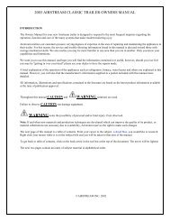
<strong>AIRSTREAM</strong><strong>OWNERS</strong><strong>MANUAL</strong>INTERSTATEA MOTORHOME GUIDE2006 MODEL RANGE
INTRODUCTION2006 MODELThe Owners Manual for your new Airstream Motorhomeis designed to respond to the most frequent inquiriesregarding the operation, function and care of the manysystems that make modern motor homing a joy.The Airstream Interstate Motorhome is integratedinto a Sprinter Van, designed and manufactured byDaimler/Chrysler. Operation of the Sprinter, its engine,power train, and other related components are discussedin the Sprinter Operator’s Manual and otherliterature provide by Daimler/Chrysler. As a point ofreference, those systems discussed in the Daimler/Chrysler literature are warranted by Daimler/Chrysleror their suppliers.Airstream realizes our customers possess varyingdegrees of expertise in the area of repairing and maintainingthe appliances in their motorhome. For thisreason, the service and trouble-shooting informationfound in this manual is directed toward those withaverage mechanical skills. We also realize you may bemore familiar in one area than you are in another. Onlyyou know your capabilities and limitations.We want you to use this manual, and hope you will findthe information contained in it useful, however, shouldyou ever feel you may be “getting in over your head”please see your dealer to have the repairs made.The operation and care of component parts suchas, refrigerator, furnace, water heater and others arebriefly explained in this manual. However, you will alsofind the complete manufacturer’s information suppliedin a packet included with this manual.Note: All information, illustrations and specificationscontained in the literature are based on the latestproduct information available at the time of publicationapproval. Airstream reserves the right to makechanges if and when new materials and/or productiontechniques are developed that can improve thequality of its product, or when material substitutionsare necessary due to availability.Throughout this manual CAUTION andWARNING notations are used.Failure to observe “CAUTION” can cause equipmentdamage if not observed..Failure to observe “WARNING” can lead todamaged equipment, serious personal injury and/ordeath if not observed.Please read and follow all cautions and warnings. Ifany questions arise contact your dealer or the factorycustomer service department.NOTE: Your Sprinter Van Operator’s and Warranty Manuals containimportant cautions, warnings, operational, and warranty informationon the Sprinter and its components. All information in theSprinter manual should be reviewed and followed for your safety.The Airstream Interstate Owner’s Manual may provide addition informationand tips on the use of the Van as a motorhome, however,no information in the Airstream manual should be interpreted asadvice or directions to disregard or void the warnings, cautions, orother information contained in the Sprinter’s manuals.© Airstream, Inc. 2006
TABLE OF CONTENTSA. WARRANTY AND SERVICEWarrantyWarranty ExplanationServiceReporting Safety DefectsMaintenance ScheduleB. DRIVINGLoadingWeighingSafety Check ListSeat BeltsTrailer Towing & Driving TipsWeighing the MotorhomeC. SPRINTER VANComponent IdentificationTire/WheelsChanging a TireInstalling a WheelD. CAMPINGCamping SafetySmoke AlarmLP Gas AlarmOvernight StopWinter TravelingExtended StayE. EXTERIORCleaningRoadside Exterior FeaturesCurbside Exterior FeaturesAwningF. INTERIOR FURNISHINGSAND ACCESSORIESLounge, DinetteVinyl FlooringCounters/CabinetsWet BathInterior SkinFabricDrape/ShadesG. PLUMBINGLP (Liquid Petroleum) GasWater SystemWater PumpCity Water HookupExterior Water ServiceFaucetsDrain Valve LocationsToiletStorage and WinterizingDrainage/Waste SystemH. ELECTRICALBattery DisconnectPower Center12-volt OperationInterior LightsMonitor SystemTV AntennaEntertainment CenterSatellite SystemTelephone JackI. 110-Volt System110-Volt PowerSwitch-over BoxShorts and OpensSolar Panel Pre-wireJ. APPLIANCESAir ConditionerFurnaceRefrigeratorRangeMicrowave OvenWater HeaterPower Roof VentK. SPECIFICATIONSCoachChassisL. INDEX
AWARRANTY AND SERVICE<strong>AIRSTREAM</strong> INC. LIMITED WARRANTYWARRANTY COVERAGEWhen you buy a new Airstream Interstate Motorhome from an authorized Airstreamdealer, Airstream, Inc., warrants the motorhome from defects in material and workmanshipas follows:BASIC WARRANTY PERIODLIMITATION OF IMPLIED WARRANTIESAll warranties of merchantability and fitness for a particular purpose, whether writtenor oral, express or implied, shall extend only for a period of three years from the dateof original purchase, or 36,000 miles (53,937 Kilometers) , whichever comes first. Thereare no other warranties, which extend beyond those described on the face hereof andwhich expressly excludes conditions resulting, from normal wear, accident, abuse,exposure or overload. Some states do not allow limitation on how long an impliedwarranty lasts, so the above limitations may not apply to you.This warranty is for 36,000 miles (53,937 Kilometers) or three years, whichever comesfirst, beginning when the vehicle is delivered to the first retail customer or first placedinto demonstrator service. This warranty must have started prior to the accumulationof 4,000 miles in order to be valid.ITEMS COVEREDAny part of the motorhome or any component equipment installed by the factory iscovered by the basic warranty except the following items, which are not covered:<strong>AIRSTREAM</strong>’S RESPONSIBILITYThe basic Airstream Limited Warranty applies for a period of three years from thedate of original purchase or 36,000 miles (53,937 Kilometers) , whichever comes first,and the application date of all warranties is that indicated on the owner’s LimitedWarranty. Defects in items covered under this Warranty will be corrected without costupon the return, at the owner’s expense, of the motorhome or defective part to anauthorized Airstream dealer.• House Battery• GeneratorThe above items will be handled by their respective service points and according totheir written policy. This limited warranty does not include failure caused by accident,abuse, normal wear, overload or any cause not attributable to a defect in originalmaterial or workmanship of the motorhome or component equipment as installedby the factory.A - 1
CARE AND MAINTENANCEThis warranty covers only defective material and/or workmanship; adjustments aremade at the factory prior to shipment, and rechecked by the dealer prior to delivery tothe customer. Adjustments thereafter become a customer responsibility.The owner is also responsible for following all recommendations, instructions andprecautions contained in the Airstream Motorhome Owner’s Manual and the individualmanuals furnished by the chassis, appliance and other manufacturers.INSTALLATIONS NOT COVEREDAirstream, Inc., does not accept any responsibility in connection with any of its motorhomesfor additional equipment or accessories installed at any dealership or otherplace of business, or by any other party. Such installation of equipment or accessoriesby any other party will not be covered by the terms of this warranty.IF REPAIRS ARE NEEDEDIf your motorhome needs repairs under the terms of the basic Airstream LimitedWarranty, you should:WARRANTY AND SERVICE3. If repairs are still not made, the customer should contact:<strong>AIRSTREAM</strong>, INC.419 W. Pike Street - P.O. Box 629Jackson Center, Ohio 45334-0629Attention: Owner Relations DepartmentFurnish the following information:• The complete serial number of the motorhome• Mileage• Date of original purchase• Selling dealer• Nature of service problem and steps or service, which have been peformed.(The owner may be directed to another dealer at theowner's expense.)4. If, after taking the above steps, repairs are still not complete, the Airstream ownermay request the motorhome be allowed to be brought to the Factory ServiceCenter at the owner’s expense.DEALER REPRESENTATION EXCLUDEDA1. Take your motorhome to your selling dealer or other Authorized Airstream Dealer.2. If the dealer is incapable of making the repair, request that he contact the ServiceAdministration Department at Airstream, Inc., for technical assistance.The full extent of the basic Airstream Limited Warranty is set forth in detail in thefolder and in the explanation of the basic Airstream Limited Warranty covered in theAirstream Motorhome Owner’s Manual. Airstream Inc. will not be responsible for additionalrepresentations or implied warranties made by any of its dealers to the extentthose representations are not a part of, or are contrary to, the terms and conditions ofthe basic Airstream Limited Warranty.A - 2
AWARRANTY AND SERVICEEXPOSURE EXCLUDEDIt is the responsibility of the owner to take such preventative measures as are necessaryto maintain the exterior caulking and sealer of your unit. It is the responsibility ofthe owner to use reasonable, prudent care to prevent foreseeable secondary damagefrom rain, plumbing leaks, and the natural accumulation of moisture in your unit, suchas a delaminated floor; stained upholstery, carpeting, or drapes; mold formation andgrowth; furniture damage, etc. Mold is a natural growth given certain environmentalconditions and is not covered by the terms of the Limited Warranty.CONSEQUENTIAL AND INCIDENTAL DAMAGESAirstream, Inc., will not be responsible for any consequential or incidental expensesor damages resulting from a defect. Incidental expenses include, but arenot limited to: travel expenses, gasoline, oil, lodging, meals, telephone tolls, andloss of work and loss of use of the motorhome. Some examples of consequentialdamages would be: stained curtains due to rain leaks or delaminated floorcaused by a plumbing leak. Some states do not allow the exclusion or limitationof incidental or consequential damages, so the above limitation or exclusion maynot apply to you.WARRANTY TRANSFERThe basic Airstream Limited Warranty is transferable to subsequent owners for theduration of the warranty period. Warranty transfer application forms are available fromyour dealer or the Airstream Inc. Service Administration Department.CONSUMER ARBITRATION PROGRAMAirstream, Inc. participates in the consumer Arbitration Program for RecreationalVehicle (CAP-RV). This third-party dispute resolution program is available, at no chargeto you, to settle unresolved warranty disputes for recreational vehicles. This disputeresolution program reviews eligible product and service related complaints involvingwarranty covered components.To find out more about this program, or to request an application/brochure, please callthe Arbitration Administration office toll-free 800.279.5343.For recreational vehicles purchased in the State of California: The CAP-RV programoperates as a certified mechanism under the review of the California ArbitrationCertification Program. You must utilize the arbitration program before claiming rightsconferred by 15 USC section 2310 (Uniform Commercial Code) or Civil Code section1793.22(b) (Son-Beverly Warranty Act). You are not required to use the program if youchoose to seek redress by pursuing rights and remedies not created by those laws.CHANGES IN DESIGNAirstream Inc. reserves the right to make changes in design and improvements uponits product without imposing any obligation upon itself to install the same upon itsproducts theretofore manufactured.This warranty gives you specific legal rights, and you may also have other rights,which vary from state to state.A - 3
WARRANTY EXPLANATIONAlong with your new Airstream motorhome, you have purchased the Airstream LimitedWarranty. Read your Limited Warranty carefully. It contains the entire agreement withrespect to Airstream’s obligation on the Limited Warranty on your new vehicle. Theterms of the Limited Warranty, and only those terms, will define Airstream’s responsibility.When you receive your Limited Warranty file it for safekeeping.WARRANTY AND SERVICEAbuseLack of customer care and/or improper maintenance, including failure to comply withthe terms of the Owner’s Manual, or failure to heed proper vehicle operation shown bythe dash instruments is not covered by warranty.ExposureAUpon proof of purchase date to any Airstream Dealer Service Center, defects in materialsor workmanship will be repaired or replaced without cost to the owner for a periodof thirty six (36) months from the original purchase date, or 36,000 miles (57,937 kilometers),whichever occurs first. Written warranties of some manufacturers of componentsof the motorhome will be honored by Airstream for the duration on that manufacturer’swarranty.The Airstream Limited Warranty Excludes:Normal Wear:Deterioration by sunlight is possible to such items as tires, curtains or upholstery.Steel or metal surfaces are subject to the elements, causing rust and corrosion that isnormal and beyond the control and responsibility of Airstream.AppearancePaint and appearance items that show imperfections, damage to interior and exteriorsurfaces resulting from abrasion, collision or impact, and broken window glass is notcovered by the Airstream Limited Warranty and should be brought to the attention ofyour Airstream dealer at the time of delivery and during pre-delivery inspection.Items such as water purifier packs, curtains, upholstery, floor coverings, window, andvent seals may show wear within the one year Limited Warranty period dependingupon the amount of usage, weather and atmospheric conditions.AccidentDamage caused by accident is usually visible, and we strongly urge our dealers andcustomers to inspect the motorhome upon delivery for any damage caused by accidentwhile being delivered to the dealer, or while it is on the dealer’s lot. Damageof this nature becomes the dealer’s or your responsibility upon acceptance of themotorhome. GLASS BREAKAGE, whether obviously struck or mysterious, is alwaysaccidental and covered by most insurance policies.OverloadOverload Damage due to loading beyond capacity or to cause improper balance is notcovered by the Airstream Limited Warranty. The Airstream motorhome is engineeredto properly handle any normal load. There are limits to the amount of load that can besafely transported depending upon speed and road conditions. If these limits havebeen exceeded the Airstream Limited Warranty will not cover resulting damage. Foradditional information on the load capacity of your motorhome, consult your Owner’sManual or gross vehicle weight rating plate.A - 4
AWARRANTY AND SERVICESPRINTER VANAirstream, Inc., does not accept any responsibility in connection with any of its motorhomesfor the Sprinter Van or its components. The Sprinter Van and its componentsare covered by DaimlerChrysler Warranties as explained by DaimlerChrysler literatureprovided with each motorhome. Your Sprinter Van and its components are precheckedby its manufacturer before delivery to Airstream. All service to the SprinterVan and its components must be performed by Daimler/Chrysler designated servicepoints according to the manufacturer’s warranty and service policies. Daimler/ChryslerLiterature is supplied with each Airstream motorhome. The literature gives importantinformation concerning its warranty coverage, maintenance, and operation.you take delivery of your new motorhome you will receive a complete checkout.Please contact your dealer if you need service. Major service under your AirstreamLimited Warranty is available through our nationwide network of Airstream DealerService Centers. An up-to-date list of Dealer Service Centers has been provided withyour new motorhome. This list is current as of the date of publication.Occasionally dealerships change, or new dealers are added who may not appear onthis list. For this reason, it is suggested that you contact your local dealer from timeto time and bring your list up to date. He can also provide you with additional copiesif you need them.WARNING: Your Sprinter Van Operator’s and Warranty Manuals containimportant cautions, warnings, operational, and warranty information on the Sprinterand its components. All information in the Sprinter manual should be reviewed and followedfor your safety. The Airstream Interstate Owner’s Manual may provide additioninformation and tips on the use of the Van as a motorhome, however, no information inthe Airstream manual should be interpreted as advice or directions to disregard or voidthe warnings, cautions, or other information contained in the Sprinter’s manuals.Other ExclusionsTires, battery and the Onan generator are serviced by their respective manufacturersand will be handled by their service centers according to the terms of their writtenpolicy. Any warranty forms from these manufacturers should be completed promptly,preferably at time of purchase.SERVICEALL SERVICE CENTERS OPERATE ON AN APPOINTMENT BASIS FOR THEUTMOST EFFICIENCY.When you require service from the Airstream Factory Service Center, or a CertifiedDealer Service Center, please contact the service manager for an appointment, andkindly inform him if you are unable to keep the appointment date or wish to change it.Service may be arranged at the Airstream Factory Service Center by contacting theService Coordinator atAirstream Factory Service CenterP.O. Box 629419 W. Pike StreetJackson Center, Ohio 45334-0629Phone: 937-596-6111Fax: 937-596-6802Before leaving the factory, each and every vital part of the motorhome is tested forperformance. Each test is signed and certified by an inspector. After the motorhomearrives on your dealer’s lot all of these vital parts and systems are again tested. WhenA - 5
CONSUMER ARBITRATION PROGRAMAirstream, Inc. participates in the consumer Arbitration Program for RecreationalVehicle (CAP-RV). This third-party dispute resolution program is available, at no chargeto you, to settle unresolved warranty disputes for recreational vehicles. This disputeresolution program reviews eligible product and service related complaints involvingwarranty covered components.To find out more about this program, or to request an application/brochure, please callthe Arbitration Administration office toll-free 800.279.5343.WARRANTY AND SERVICEREPORTING SAFETY DEFECTSIf you believe that your vehicle has a defect, which could cause a crash or could causeinjury or death, you should immediately inform the National Highway Traffic SafetyAdministration (NHTSA) in addition to notifying Airstream, Inc.If NHTSA receives similar complaints, it may open an investigation, and if it finds that asafety defect exists in a group of vehicles, it may order a recall and remedy campaign.However, NHTSA cannot become involved in individual problems between you, yourdealer, or Airstream, Inc.AFor recreational vehicles purchased in the State of California: The CAP-RV programoperates as a certified mechanism under the review of the California ArbitrationCertification Program. You must utilize the arbitration program before claiming rightsconferred by 15 USC section 2310 (Uniform Commercial Code) or Civil Code section1793.22(b) (Son-Beverly Warranty Act). You are not required to use the program if youchoose to seek redress by pursuing rights and remedies not created by those laws.To contact NHTSA you may either call the Auto Safety Hotline toll-free at 1-800-327-4236 (TTY 1-800-424-9153) or write to: NHTSA, 400Seventh ST, S.W., Washington,D.C. 20590.You can also obtain other information about motor vehicle safety from the Hotline orview the NHTSA Website: www.safecar.govA - 6
WARRANTY AND SERVICEMAINTENANCE SCHEDULEEVERY YEAR or 12,000 milesALiving AreaLP TankClean, neutralize and coat terminalswith petroleum jelly.WARNING: FAILURE TO MAINTAIN YOUR COACH CAN CAUSEPREMATURE AND UNEXPECTED PARTS BREAKAGE AND/OR ERRATICSeamsCheck and reseal, windows, lights and ventsOPERATION THAT MAY BE HAZARDOUS. SERIOUS INJURY COULD RESULTif necessary. Reseal with Bostik urethaneFROM FAILURE TO HEED THIS WARNING.sealant or equivalent as needed.EVERY 1,000 MILES OR 60 DAYSAPPLIANCESSmoke AlarmGFI Circuit BreakerEVERY 5,000 MILES OR 90 DAYSLPG RegulatorRoof Vent Elevator ScrewsTest and replace battery as required.Test and record.Check bottom vent for obstructionsLubricate with light household oilAppliances have maintenance schedules and advice in their respective Owners/Operation Manuals. These manuals are included in the owner’s packet given toyou by your dealer. Please become familiar with and follow all information inthese manuals.AUTOMOTIVESee the Sprinter Operators Manual and Maintenance Logbook for AutomotiveMaintenance schedules and pre-trip inspections.Living Area WindowsLubricate with light household oilEVERY 10, 000 MILES OR 6 MONTHSCarbon monoxide alarmVacuum exterior only.A - 7
MAINTENANCE RECORDSDATE DEALER SERVICE PERFORMEDWARRANTY AND SERVICEDATE DEALER SERVICE PERFORMEDAA - 8
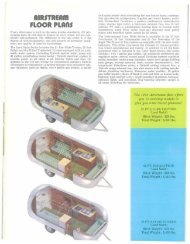
BDRIVINGLOADINGBelow is a sample of the weight information chart provided in all Airstream vehicles.This information can be found in your vehicle on the back of a wardrobe door about60” up from the floor.Do you really want to carry 300 pounds of water to a RV park 1,000 miles away andthen hook up to a city water supply? Even if you’re going to the “boondocks”, you canusually fill your water tank shortly before entering the area. Just reducing your load by10 gallons of water lets you carry an awful lot of fishing and camping gear.The Unloaded Vehicle Weight (UVW), listed on the chart in your coach, is the weightof this motorhome as manufactured at the factory with full fuel, engine oil, and coolants.Cargo Carrying Capacity (CCC) is equal to the GVWR minus each of the following:UVW, full fresh (potable) water weight (including water heater), full propane weight,and SCWR.WEIGHINGSee specification section in this manual for weights and term definitions.WEIGHT DISTRIBUTIONThe unloaded vehicle weight (UVW), listed on the chart in your coach is the weight ofthe motorhome with the options as ordered and installed at the factory. It includes allweight at the axles with full generator fluids, including fuel, engine oil, and coolants.To determine the actual weight of your vehicle with personal cargo, water and LP, itmust be weighed on scales. The most common scales are those used by states toweigh trucks used along the highway. In rural areas, grain elevators are a good sourceand another would be a gravel pit. Note: Weighing instructions for this motorhome areexplained later in this section.If you have trouble locating scales, a call to your State Highway Patrol will usually findthem very cooperative in assisting you.The motorhomes have fresh water, a wastewater tank, and storage areas. It gives yougreat flexibility in loading. With flexibility comes responsibility. If you want to load downall the storage compartments, the amount of fluids will have to be reduced. Distributeyour additional cargo as evenly as possible with the heaviest objects located as lowas possible.B - 1
DRIVINGSAFETY CHECK LIST10. Keep tires at recommended inflation pressure.Your Airstream motorhome should be given a thorough safety check before a trip.Regular use of the following list will provide safe operation of your motorhome andwill help you spot any malfunctioning equipment and correct the problem as soon aspossible. The list is to help you and may not be all-inclusive.Failure to heed the following items may cause damage to the vehicle or personalinjury.INTERIOR CHECK LIST (BEFORE DRIVING OFF)1. It is important that all doors be completely closed during travel.2. Turn off living area water pump.3. Check that refrigerator door is fastened.BEXTERIOR CHECK LIST (BEFORE ENTERING VEHICLE)1. Check condition of tires for proper inflation.2. Turn off LPG valve on LPG tank.3. Check that sewer connections, city water hookup, TV cable/satellite, and allexterior components are unhooked and properly stowed away.4. Check that all external compartments and filler openings are properly closed,latched, and/or locked.5. Check that items stored on exterior of vehicle are securely tied down.4. Check that nothing heavy is stored in overhead or high cabinets, which could fallout and cause injury. Heavy items should be stored in lower cabinets.5. Stow folding and pedestal tables.6. Check that counter tops, range top, and shelves are clear of even small items thatcould become projectiles in an accident.7. Do not cook while under way. Hot food or liquid could scald due to a sudden stopor accident.8. Be sure all LPG controls on the furnace, range and gas/electric refrigerator areturned Off.6. Would any items stored on exterior of vehicle present a clearance problem?9. Check that any internal stowage is securely held in place7. Lower and secure TV antenna, (stow satellite dish).10. Check that lights and switches are set in positions safe for travel.8. Follow all automotive manufacturers recommendations on checking and fillingfluid levels.9. Check exterior lights and general condition of vehicle.11. Adjust the driver’s seat so that you can easily reach and operate all controls.Make sure seat is locked in position. Do not adjust driver’s seat’ swivel, fore or aftmechanism while vehicle is moving. The seat could move unexpectedly causingloss of control.B - 2
DRIVINGB12. Check that front passenger’s seat is locked in position - both fore and aftadjustment and swivel mechanism.13. The freedom of movement of the brake and accelerator pedals must not beimpaired in any way14. Check rear view mirrors adjustment, inside and outside. Adjust curtains ifnecessary for maximum visibility.15. Secure children in a Federally Approved Child Restraint Device.16. Fasten your lap belts.SAFETYWARNING: Children must be secured in a Federally Approved ChildRestraint Device. Failure to use proper restraints while in transit can result insevere or fatal injuries. Never place an infant seat that faces to the rear on thefront passenger seat. Never place an unbelted infant seat on the front passengerseat.Child restraint devices are designed to be secured with lap or lap/shoulder belts. Allinstructions supplied by the restraint manufacturer must be followed. Statistics haveshown children are safer when properly restrained in a rear seating position than in afront seating position.Often the children traveling in motorhomes are grandchildren. There are times whenour love for grandchildren makes us hesitate to properly supervise their actions. Don’thesitate when it comes to their safety. Make sure they are properly restrained.SEAT BELTSIn the forward driver’s area of the motorhome, safety seat belts are provided for the useof the driver and the right front passenger. Safety belts are available for other seats.It is strongly recommended that all occupants remain seated with their safety beltsfirmly attached while the motorhome is in transit. The driver should adjust his seat sothat he is able to reach all controls easily with the belt on, especially able to use all thetravel on the foot brake. The belt should be placed as low as possible around the hipsto prevent sliding out from under them in case of accident. This places the load of thebody on the strong hipbone structure instead of around the soft abdominal area. Twopeople should never try to use the same seat belt.CHILDREN HAVE LOVED ONES TOO.IF YOU WON’T BUCKLE UP FOR YOURSELF, BUCKLE UP FOR THEM.WARNING: Drinking or taking drugs and driving can be a very dangerouscombination. Even a small amount of alcohol or drugs can affect your reflexes,perception, and judgment. The possibility of a serious or even fatal accident issharply increased when you drink or take drugs and drive. Never drink or takedrugs and drive or allow anyone to drive after drinking or taking drugs.WARNING: Become familiar with and follow all directions, advice, andwarnings pertaining to seats, seat belt operation, and restraint systems, providedin the Sprinter Operator’s Manual.B - 3
TRAILER TOWING AND DRIVING TIPS(partial excerpts from Sprinter Operators Manual)WARNING: Failure to use proper equipment and driving technique canresult in a loss of vehicle control when towing a trailer. Improper towing or failureto follow the instructions contained in this section can result in serious injury.Follow the guidelines below carefully to assure safe trailer operation. Ask yourauthorized sprinter or Airstream dealer if you require an explanation of informationcontained in the sky.DRIVINGVehicle and Trailer Weights and RatingsGross Vehicle Weight Rating (GVWR) is the maximum permissible weight of the motorhome.Gross Vehicle Weight (GVW): comprises weight of vehicle including fuel, tools, sparetire, installed accessories, passengers, cargo, and trailer tongue. It must never exceedthe GVWR.Gross Axle Weight Rating (GAWR) is a maximum permissible axle weight.BTrailer HitchesGross Trailer Weight (GTW) is a maximum permissible trailer weight to be towed.Units have hitches installed from the Sprinter manufacturer. The Sprinter 7- way connectoris used for lights and charge line on a trailer. For further information, please seeyour authorized Sprinter or Airstream Dealer.The bumpers on your vehicle are not designed for use with clamp type hitches. Do notattach rental hitches or other bumper type hitches to them.Trailer Tongue Weight Rating (TWR) is the maximum permissible weight of thetrailer tongue.These and other weights are located in the specification section of this manual.To reduce the possibility of damage, remove the hitch ball adapter from the receiverwhen not in use.B - 4
DRIVINGBSince this vehicle is designed and intended primarily as a load-carrying vehicle, towinga trailer will affect handling, durability and economy. Maximum safety and satisfactiondepends upon proper use of correct equipment and avoiding overloads and otherabusive operation.WARNING: The total weight of the motorhome and trailer must not exceedthe GCWR listed in the specification section of this manual. The maximumtowing capacity varies according to the size of the motorhome and its GCWR.Vehicles should be properly equipped for towing trailers. Information on trailerhauling capabilities and special equipment required may be obtained from yourAirstream dealer.When towing trailers, motorhome tires should be inflated to the highest pressuresshown on the information plate on the side of the driver’s seal mounting plate. TheCargo Carrying Capacity (CCC) of this vehicle is reduced by the amount that equalsthe trailer tongue load on the trailer hitch.Checking Weights of Vehicle and TrailerTo assure that the tow vehicle and trailer comply with the maximum permissible weightlimits, and to know the actual weights, have the loaded vehicle-trailer combination(tow vehicle including driver, passengers and cargo, trailer fully loaded) weight oncommercial scale.Loading a TrailerWhen loading a trailer, you should observe that neither the permissible GTW, nor theGVWR are exceeded.Check the vehicles front and rear Gross Axle Weight (GAW), the GTW and TW. The valuesas measured must not be exceeded, according to the weight listed under “Vehicleand trailer weight and ratings” in this section.Maximum permissible values are listed on the safety compliance certification labelsfor the vehicle and for the trailer to be towed. For their location, see the SprinterOperators Manual. The lowest value listed must be selected when determining howthe vehicle and trailer are loaded.To assist in attaining good handling of the vehicle/trailer combination it is importantthat the tongue weight be maintained at approximately 10%-15% of the loaded trailerweight, but not to exceed the hitch rating. Tongue loads can be adjusted by properdistribution of the load in the trailer, and can be checked by weighing separately theloaded trailer and then the tongue.The tongue weight (TW) at the hitch ball must be added to the GVW to prevent exceedingyour Sprinter towed vehicles or rear GAWR.B - 5
DRIVINGAttaching a TrailerPlease observe maximum permitted trailer dimensions (weight and length).Most states and all Canadian provinces require safety chains between your tow vehicleand trailer. The chains should be crisscrossed under the trailer tongue. It must beattached to the hitch receiver, and not to the vehicles bumper or axle. Be sure to leaveenough slack in the chains to permit turning corners.Most states and all Canadian provinces required a separate brake system for towingtrailers.WARNING: Do not connect a trailer brake system (if trailer is soequipped) directly to the vehicles hydraulic brake system as your vehicle isequipped with antilock brakes. If you do, neither the vehicles brakes nor thetrailers brakes will function properly. Property damage, injury or death to youor others may be the result. The provided vehicle electrical wiring harness fora trailer towing has a brake signal wire for hookup to a brake controller. Moststates and all Canadian provinces require a brake away switch on trailers witha separate brake system. The switch activates the trailer brakes in the possibleevent that the trailer might separate from the tow vehicle. Please consider usinga trailer sway control system. For further information, see your authorizedSprinter or Airstream dealer.BWARNING: The towing vehicle’s braking system is rated for operationat GVWR (GROSS VEHICLE WEIGHT RATING), NOT at the GCWR (GROSSCOMBINED WEIGHT RATING). A separate functioning brake system is requiredfor any towed vehicles or trailers weighing more than 1000 lbs. (450 kg) whenfully loaded. NEVER exceed the GVWR (GROSS VEHICLE WEIGHT RATING), orthe GAWR (GROSS AXLE WEIGHT RATING) specified on a motorhome certificationlabel. Also NEVER, exceed the weight ratings of trailer hitch installed ona motorhome. Failure to heed any part of this warning could result in loss ofcontrol of the motorhome and towed vehicle or trailer and may cause an accidentand serious injury. For specified towed vehicle braking requirements, consult theSprinter Operator’s manual that comes with this vehicle.Towing a TrailerThere are many different laws, including speed limit restrictions, having to do withtrailer towing. Make sure that your vehicle -- trailer combination will be legal; notonly for where you reside, but also for where you’ll be driving. A good source for thisinformation can be the State Attorney General, State Police, or local authorities.Before you start driving with a trailer, check the trailer’s hitch, brake away switch,safety chains, electrical connections, lighting and tires. Also, adjust the mirrors topermit unobstructed view beyond rear of trailer.B - 6
BDRIVINGIf the trailer has electric brakes, start your vehicle and trailer moving slowly, and then applyonly the trailer brake controller by hand to be sure the brakes are working properly.When towing a trailer, check occasionally to be sure that the load is secure, and thatlighting and trailer brakes (if so equipped) are functioning properly.Always secure items in the trailer to prevent load shifts while driving.Take into consideration that when towing a trailer, the handling characteristics aredifferent and less stable from those when operating the vehicle without a trailer. It isimportant to avoid sudden maneuvers.OBSERVE THAT THE TRACKS MADE BY THE TRAILER WHEELS ARE DISTINCTLYDIFFERENT FROM THOSE MADE BY THE TOW VEHICLE. Studying this will make iteasier for you to correct mistakes. Truck or trailer type fender or door grip rear view mirrorsare necessary for maximum visibility and in most states the law requires them.After thoroughly inspecting your hitch, brakes, and tires you should be ready to tow.Check traffic, signal that you are about to pull away, and start slowly. Look often in yourmirrors, and observe the action of the trailer, then carefully move into the proper laneof traffic. Remember that the trailer wheels will not follow the path of the tow vehiclewheels; therefore, WIDER TURNS ARE NECESSARY WHEN TURNING TO THE LEFTOR TO THE RIGHT.The vehicle and trailer combination is heavier, and therefore is limited in accelerationinclining ability, and requires longer stopping distances. It is more prone to reacting toside wind gusts, and requires more sensitive steering input.In order to gain skill and an understanding of the vehicles behavior, you should practiceturning, stopping and backing up in an area which is free from traffic.ON FREEWAYS OR EXPRESSWAYS try to pick the lane you want and stay in it. Alwaysmaintain plenty of space between you and the car ahead, at least the length of the towvehicle plus trailer for every ten miles per hour. Remember that in order to pass anothervehicle you will need longer to accelerate. You must also allow for the length of thetrailer when returning to the right hand lane.If possible, do not brake abruptly, but rather engage the brake slightly at first to permittrailer to activate its brake. Then increase the braking force.We want every owner to be a safe and courteous driver. A few hours of towing practicein a large empty supermarket lot will make pulling your trailer over the road mucheasier. Line out two corners for left and right turns. You may also use these corners topractice backing and parking.B - 7
DRIVINGwhen the vehicle is cool.When going downhill in dry weather, down shift so thatengine compression will slow the whole rig clown. Takedips and depressions in the road slowly and do notresume normal driving speeds until you are sure thatthe trailer wheels are clear of the dip.BTrackingOn a two-lane road cars will be lining up behind youbecause you travel at a lower speed. It is both courteousand sensible to signal, pull onto the shoulder, andlet them pass.The BRAKE CONTROLLER (if so equipped) is activatedwhen you apply the brakes of the tow vehicle. Yourtow vehicle brakes will automatically apply the trailerbrakes first when properly adjusted. This will help keepyour tow vehicle and trailer in a straight line and makeyou stop as if you were driving the tow vehicle alone. Ifswaying or swerving should occur, briefly operating thecontroller separate from the vehicle brakes may helpcorrect the situation. Practice this maneuver on a clearhighway. Don’t wait for an emergency then grope forthe controller.When trailering you might encounter a temporary coolingsystem overload during severe conditions such ashot days when pulling on a long grade, when slowingdown after higher speed driving, or driving long idleperiods in traffic jams. If the hot indicator light comeson, or the temperature gauge indicates overheatingand you have your air conditioner turned on, turn it off.Pull over in a safe place and put on your emergencybrake. Don’t turn off the engine. Increase the engineidle speed. Lift the engine hood and check for fluidleaks at the radiator overflow outlet. Check to see thatall drive belts are intact and the fan is turning. If youhave a problem have it fixed at the next opportunity. Ifthere is no problem the light should go off or temperatureshould come down within one minute. Proceed onthe highway a little slower. Ten minutes later resumenormal driving.WARNING: Never open a radiator capwhen the tow vehicle is hot. Check the coolant levelWARNING: On slippery pavement do notuse engine drag to help slow down as this maycause the rear wheels of the tow vehicle to skid.On icy pavement drive slowly and if you feel the towvehicle skidding gently apply the trailer brakes only.This will bring the tow vehicle and trailer back into asingle line. Chains do not help trailer wheels.When driving in mud and sand let the momentum carrythe rig through. Apply power gently and use as little aspossible. Stay in the tracks of the vehicle ahead andkeep the tow vehicle in the highest possible gear. If youare stuck it is best to tow out the entire rig togetherwithout unhitching.Despite the best hitch you will notice that whenevera large bus or truck overtakes your rig the displacedair first pushes the trailer rear slightly to the right andthen affects the front. It may be necessary to steer veryslightly, momentarily, toward the bus or truck to helpcompensate for the sway induced by the passing-vehicle.Do not apply the vehicle brakes, as this can tendto exaggerate the situation. You may find, however,that briefly applying the trailer brakes with your manualB - 8
BDRIVINGcontrol will help eliminate sway.WARNING: When stopping on a hill or slope, leaving your tow vehiclein gear is not enough for standstill safety. CHOCK THE TRAILER WHEELS to hedouble sure. Do not use trailer brakes as parking brakes.Backing UpIn BACKING UP the important thing to remember is to DO EVERYTHING SLOWLYand to correct immediately if you see the trailer turning the wrong way. Concentrateon the rear of the trailer. With your tow vehicle and trailer in a straight line, back upslowly and turn the bottom of the steering wheel in the direction you want the trailer togo. Watch out the window or in the mirror until the rear of the trailer is pointing in thedesired direction. Your tow vehicle will be following the trailer in an arc. Straighten thetow vehicle and trailer by turning the steering wheel more sharply, and then when theyare in line, straighten the steering wheel.CAUTION: If the transmission hunts between gears on inclines, manually shift toa lower gear (select “4”, “3”, “to “2” or “1”). A lower gear and reduction of speedreduces the chances of engine overloading and/or overheating. When going down along hill, shift into a lower gear and use the engines braking effect. Avoid riding thebrakes, thus overheating the vehicle and trailer brakes. If the engine coolant rises toan extremely high temperature (coolant temperature needle approaching the red zone)when the air conditioner is on, turn off the air conditioner. Engine coolant heat can beadditionally vented by opening the windows, switching the climate control fan speedto high and setting the temperature control to the maximum hot position. Extreme caremust be exercised censure vehicle with a trailer will require additional passing distanceahead that when driving without a trailer. Because your vehicle and trailer is longerthen your vehicle alone, you will also need to go much further ahead of the passedvehicle before you can return to your lane.ParkingALWAYS TRY TO BACK TO YOUR LEFT BECAUSE THE VISIBILITY IS MUCH BETTER.(See Illustration) When you don’t make it on the first try it is usually much easier to pullforward to your original position and start over.If your spouse or traveling companion normally directs you when backing they shouldposition themselves forward of the tow vehicle so the driver can easily see them. Theirdirections should always indicate to the driver the direction the rear of the trailer shouldgo. A little practice in a parking lot with the person giving directions can save a lot offrustration when backing into a campsite.WARNING: take into consideration that when towing a trailer, the handlingcharacteristics are different and less stable from those with operating thevehicle without a trailer. It is important to avoid sudden maneuvers. Suddenmaneuvers may lead to loss of control over the vehicle -- trailer combination.WARNING: to reduce the risk of personal injury, or damage to the vehiclepower train, as a result of vehicle/trailer movement, always:• Keep right foot on the brake pedal.• Shift tear selector lever to position "N".• Have a second person place wheel chocks on downhill side of left andright trailer wheels.• Slowly release brake pedal cannot vehicle and trailer roll into chocksuntil stopped.• Firmly depress parking brake pedal.• Move gear selector lever to position "P".• On inclines, turn from wheels towards the road curb.B - 9
DRIVINGTOWING YOUR MOTORHOMEThe most common equipment is called “reach under hooks”. These allow the towoperator to lift on the front suspension of your motorhome without damaging thebumper or other body parts. Another choice is a wheeled dolly. In these, the fronttires sit in a cradle supported by its own wheels. The tow operator should be told theweight of your vehicle on the front suspension so they can be properly prepared whenthey reach you.BCAUTION: Considerable damage will occur if the motorhome is improperlylifted for towing purposes. Only qualified professional wrecker service companieswith proper equipment should be used. Observe all cautions and warningsin the Sprinter Operator’s manual before towing your motorhome.WARNING: Do not tow the vehicle if the key cannot be turned in the ignitionlock. If the key cannot be turned, the ignition lock remains locked and the vehicle cannotbe steered. With the engine not running there is no power assistance for the brakingand steering systems. In this case, it is important to keep in mind that a considerablyhigher degree of effort is necessary to brake and steer the vehicle. The vehicle mustnot be towed with the front axle raised and key in position two in the ignition lock asthe drive wheels could then lock due to the acceleration skid control (ASR). See theSprinter Operators Manual for information on the ASR.B - 10
DRIVINGFront Axle GAWR GVWR Rear Axle GAWR GCWR - GVWProcedure for Weighing A RVVehicle should be weigh loaded as youBSCALE WEIGHTOptional Tow Weightnormally travel.1. Fill in first row from SpecificationSection of this manual.2. Weigh vehicle as shown in row 2(Scale Weight) and fill in blanks.___________STEP 1Front Axle GAW___________STEP 2GVW___________STEP 3Rear Axle GAW___________STEP 3aTow Weight minusWeight of Traileror Vehicle Towed3. Weigh one side of vehicle as shown InIndividual Wheel Position Weight.4. Calculate other side as shown in LastInformation for line 1 is located in theINDIVIDUAL WHEEL POSITION WEIGHTspecification section in this manual.___________STEP 4Left Front WheelPosition___________STEP 5Left Side(Total LF + LR)___________STEP 6Left Rear WheelPositionCalculated Calculated Calculated___________Right Front WheelPositionStep 1 minus Step 4___________Right Front(Total RF + RR)Step 2 minus Step5___________Right RearWheel PositionStep 3 minus Step 6GAWR = Gross Axle Weight RatingGVWR = Gross Vehicle Weight RatingGCWR = Gross Combination Weight RatingB - 11
SPRINTER VANComponent IdentificationIn the United States:In Canada:The Airstream Interstate Motorhome is integrated into a Sprinter Van, designed andmanufactured by Daimler/Chrysler. Operation of the Sprinter, its engine, power train,and other related components are discussed in the Sprinter Operator’s Manual andother literature provide by Daimler/Chrysler. As a point of reference, those systemsdiscussed in this literature are warranted by Daimler/Chrysler or their suppliers.If repairs are needed, it may be difficult to determine which parts are the Sprintermanufacturer’s, and which are Airstream’s responsibility. The following partial lists showthe major components of the van and the company responsible for their servicing.Daimler/Chrysler Motors Company LLC Daimler/Chrysler Canada, Inc.Customer CenterCustomer CenterPO Box 21-8004 PO Box 1621Auburn Hills, MI. 48321-8004Windsor, Ontario N9A-4H6Ph.: 800-992-1997 Ph.: 800 465-2001CSprinter Van Serviced by Daimler/Chrysler.See Sprinter Warranty Information Manual for complete instructions.EngineTransmissionBrakesSteering AssemblyFront Spindle, BearingsWheelsAlternatorCruise ControlInstrument Panel ClusterTires (see tire manufacturer service center)Cab door windows and windshieldDash AC/Heater/DefrosterExterior Automotive lightsSuspensionDrive Axle and HubsRear ShocksAutomotive Fuse PanelParking BrakeElectric Fuel PumpEngine BatteryEngine Cooling SystemDoors, cab, side and rear cargoAutomotive electrical systemDriver’s and Passenger’s Seats and Restraint systems, does not include optionalswivel pedestal for passenger seat or seat decorative skirting that is installed byAirstream Inc.C - 1
SPRINTER VANComponent Identification (continued)ExteriorCAirstream Components serviced by Airstream Authorized Service CentersCab Area:Driving light system including lights, switch and harnessDriver’s and passenger’s seat skirtingFloor MatsFinish on the center console switch base. Airstream removes, send out for finish andreinstalls.Living Quarters:Interior furniture, wall panels to the rear of the cab seats.Privacy curtainShadesFloor coveringAppliances in the lounge/lavy areaFresh water and waste water system components.Roof rackEntertainment center’s Radio and TV antennaExterior windows excluding windshield, drivers and passenger doorPaint (Carrera Designs)Access doors and other living area electrical and plumbing componentsIf you need further clarification or information, contact the Airstream Customer RelationsDepartment at 937-596-6111 before contacting a service center for an appointment.If you wish to write, the address is:Airstream Inc.Attn: Customer Service419 W. Pike StreetP.O. Box 629Jackson Center, Ohio 45334Non-automotive electrical components including:Monitor panel and its systemConverterAutomatic switchover box110-volt system12 Volt living area systemRoof ACPower ventLiving area entertainment centerExterior patio lightC - 2
IMPORTANT INFORMATIONYour Sprinter Van Operator’s and Warranty Manuals contain important cautions,warnings, operational, and warranty information on the Sprinter and its components.All information in the Sprinter manual should be reviewed and followedfor your safety. The Airstream Interstate Owner’s Manual may provide additioninformation and tips on the use of the Van as a motorhome, however, no informationin the Airstream manual should be interpreted as advice or directions todisregard or void the warnings, cautions, or other information contained in theSprinter’s manuals.TIRESDon’t let anyone tell you that underinflation or over inflation is all right. It’s not. If you’retires don’t have enough air (underinflation) you can get tire flexing, heat build-up, tireoverloading, bad handling, bad fuel economy, and bad wear. Too high an air pressure(over inflation) can result in abnormal wear, bad handling, harsh ride, and increase thechance of damage from road hazards.SPRINTER VANProper FRONT END ALIGNMENT improves tire tread mileage. Your front-end suspensionparts should be inspected periodically and aligned when needed. Improper alignmentmay or may not cause the vehicle to vibrate. However, improper toe alignmentwill cause front tires to roll at an angle, which will result in faster tire wear. Incorrectcaster or camber alignment will cause your front tires to wear unevenly and can causethe vehicle to “pull” to the left or right.Vehicle Placard and Tire Inflation Pressure LabelThe TIRE AND LOADING INFORMATION placard supplies information on the sizeand the cold tire inflation pressure for the original equipment tires supplied with yourvehicle. It also defines the GVWR as 8,550 pounds. It is located on the side of thedriver’s seat pedestal in your vehicle.CTire inflation pressures should be checked at least monthly and when significantlychanging the load you plan to carry in your motorhome. Always check tire inflationpressures when the tires are “cold”.Standard inflation pressures for tires are listed on a decal mounted on the driver’s seatpedestal. Front and rear pressures are shown for each model and GVWR, and arebased on the GVWR and front and rear axle ratings (GAWRs) printed on your vehicleVIN plate and Certification label. Tires must be inflated to these pressures when thevehicle is fully loaded or an axle GAWR is reached.C - 3
CSPRINTER VANPROPER TIRE INFLATIONThe level of air in your tires affects your vehicle’s overall performance. Not even thehighest quality tire will perform well if it’s not inflated properly. The correct pressurevaries from vehicle to vehicle and depends in part upon driver preference. Each vehiclehas a recommended inflation pressure, usually found on a placard on the door section,doorpost, glove door, or fuel door. On the Interstate Motorhome, it is located on theDriver’s seat pedestal.Correct tire inflation is a key component in tire care. The recommended inflation pressuresfor your tires are indicated on the certification label or in your owner’s manual.Since RVs can be loaded with many different configurations, the load on each tirewill vary. For this reason, air pressure should be checked based on the load on eachindividual tire. Cold Inflation Pressure should be adjusted to handle the maximum tireload, and all tires on the axle should carry the same inflation pressure. COLD TIREINFLATION PRESSURE is the tire pressure checked in the morning before you drivemore than a few miles or before rising ambient temperatures or the sun’s radiant heataffects it. Check your tires’ air pressures at least once a month, before each trip andeach morning you drive during a trip. Tire pressure should be checked cold, as tirepressure ratings have been designed with typical running heat/pressure build-up inmind. Make sure the valves and caps are free of dirt and moisture.Under InflationUnderinflation brings a higher risk of susceptibility to damage due to road hazards,reduces casing durability, and causes a loss in fuel economy, plus uneven or irregulartire wear. Severe underinflation brings about an increased risk of tread separation,handling difficulties, and possibly tire failure, which is caused by overheating.IMPORTANT: It’s a common practice for RV owners to lower tire pressure in theirsearch for a smoother ride. This is not only dangerous, it’s relatively ineffective, andas the difference in ride quality is not significant. When minimum inflation pressurerequirements are not met, tire durability and optimum operating conditions are compromised.Tire inflation pressure should always meet at least the minimum guidelinesfor vehicle weight.• It may be necessary to inflate your tires at a truck stop or truck servicecenter in order to achieve adequate air pressure for your coach's needs• Only permanent air seal metal valve caps should be used.• Be safe - if a tire has been run 20% under inflated, it must be dismountedand inspected by a trained professional. It should not be aired up withouta full inspection or without using a safety cage. Use a calibrated gauge.If your tire is rated for higher inflation pressures, a special gauge will berequired designed for larger tires.• Don't bleed air from warm tires to reduce pressure buildup• Don't inflate tires to cold PSI rating beyond rim specificationsHOW OVERLOADING AFFECTS YOUR TIRESTire pressure is what enables your RV tire to support loads. Overloading your tirescan have serious consequences for passengers and your RV. Too much weight cancause stress on your RV’s suspension system, brake failure, shock absorber damage,handling and steering problems, irregular tire wear and possible tire failure.Excessive loads or underinflation can lead to an excessive amount of heat and tirefailure. If you discover that your tires cannot handle the load, lighten the weight ofthe load on your tires.Tire pressure should never be reduced below the vehicle manufacturer’s recommendedlevels to support load conditions in order to improve the ride quality of a vehicle. Thedifference in ride quality is not significant. When minimum inflation pressure requirementsare not met, tire durability and optimum operation can be affected.C - 4
SPRINTER VANTIRES and WHEELS (partially excerpted from the Sprinter Van Operator’s Manual)Do not use remolded tires.Check tires regularly for even tread wear; tread depth (note legal requirements) andsigns of external damage.Use only wheels and tires of the same size, make and pattern.Do not install tires that are not approved for the size and type of wheel installed onthe vehicle itself. Only use those wheel sizes that were delivered to you buy yourauthorized Sprinter dealer.Use only wheels and tires that have been tested and approved by thevehicle manufacturer.Break in the tires at moderate speeds for distance of about 65 miles.Tighten the wheel bolts or nuts in a cross pattern sequence.Tighten the wheel bolts or nuts to the specified torque with a torque wrench.Tightening Torque for 8,550 lbs. (vehicle type 2500 C/HC/SHC):Steel Wheel177 Lbf/ Ft. + or - 7 Lbf. /Ft.Light Alloy Wheel138 Lbf/ Ft. + or - 14 Lbf. /Ft (optional)Tire GripTire grip is greatly reduced on a wet or icy road. Speed and driving style must thereforebe adapted to suit road conditions. In winter, install M + S radial tires. Below a treaddepth of 1/8 in., tire grip begins to decrease rapidly on wet roads.CWARNING: always replace wheel bolts that are damage or rusted.Never apply oil or grease to wheel bolts. Damaged wheel hub threads should berepaired immediately. Incorrect mounting bolts or improperly tighten mountingbolts can cause the wheel to come off. This could cause an accident. Be sureto use the correct mounting bolts. Checked tightness of wheel bolts or nutsregularly and retighten if necessary.HydroplaningDepending on the depth of the water layer on the road, hydroplaning may occur, evenat low speeds and with new tires. Reduce vehicle speed, avoid grooves in the road,and apply brakes cautiously in the rain.After changing a wheel, the wheel bolts or nuts must be tightened once the vehiclehas been driven for about 30 miles.If new or repainted wheels are fitted, the wheel bolts or nuts must be retightenagain after about 600 to 3000 miles.Fitting other wheel sizes to the vehicle will change the Sprinter’s handling characteristicsand may lead to an accident resulting in severe personal injuries,death and property damage.C - 5
CSPRINTER VANChanging the Tire (partially excerpted from the Sprinter Van Operator’s Manual)If you get a flat tire while driving, gradually decrease your speed. Hold the steeringwheel firmly and slowly move to a safe place on the side of the road. The pressure ofthe spare wheel always has to be checked regularly (at least after every tenth time atthe filling station).The vehicle tool kit and the jack are located under the hatch in the front passengerfoot well.• Precautions when changing a wheel:Tire pressure: See Sprinter Van Operator’s Manual.Wheel bolt torqueTighten the wheel bolts in a crosswise pattern to the specified torque withtorque wrench.Tightening Torque for 8,550 lbs. (vehicle type 2500 C/HC/SHC):Steel Wheel 177 Lbf/ Ft. + or - 7 Lbf. /Ft.Light Alloy Wheel 138 Lbf/ Ft. + or - 14 Lbf. /Ft (optional)• Do not damage, grease or oil wheel bolts or their threads.WARNING: The jack is designed exclusively for jacking up the vehicleat the jack take-up brackets built into either side of the vehicle. To help avoidpersonal injury, use the jack only to lift the vehicle during a wheel change. Neverget beneath the vehicle while it is supported by the jack.• Keep hands and feet away from the area under the lifted the vehicle.• Always firmly set parking brake and block wheels before raisingvehicle with jack.• Do not disengage parking brake while vehicle is raised.• Always use the jack on a level surface.• Do not jack the vehicle up more than 1.2 inches between the tire andthe surface. Otherwise, the vehicle may tip over and may cause seriousinjury or death to you or others.• Be sure that the jack arm and is fully seated in the jack take-upbracket.• Always lower the vehicle onto sufficient capacity jack stands beforeworking under the vehicle.Procedure:• Park the vehicle on a firm, level, non-slippery surface.• Switch on the hazard warning flasher switch, apply the parking brake, andplace the transmission selector in “P”.• Everyone must leave the vehicle before you jack it up.• Everyone must leave the danger zone, before jacking the vehicle.• The vehicle must be safeguarded in accordance with legal regulations(such as using a warning triangle).• Prevent vehicle for rolling away by blocking wheels with wheel chocks (notsupplied with vehicle) or sizable woodblocks or stone. On a level roadplace one chalk in front of and one behind the wheel that is diagonally oppositeto the wheel being changed. When changing a wheel on mild uphillor downhill grade, place chocks on the downhill side blocking both wheelsof the other axle.C - 6
SPRINTER VANChanging the Tire (continued)USING THE JACKWARNING: do not change wheels on either a steep uphill or downhillgrade. The vehicle may begin to move and fall from the jack, which could causepersonal injury and property damage.SPARE WHEEL LOCATION: The spare tire on the Mid Bath models is located asexpalined in the Dodge Sprinter Manual.On the Rear Bath model the spare tire has been moved from its original location beneaththe end of the frame to just inside the rear doors of the motorhome. It is securedby straps.The jack is located together with vehicle tool kit under the hatch in the front passengerfoot well.• Loosen the wheel bolts before raising the vehicle.• Close the release valve on the jack.• Assemble the pump lever provided and insert it into the socket on the jack.• Secure lever by turning it clockwise in the socket.• Position the jack under the appropriate jack point and raise the vehicle bypumping the lever.Note: see the Sprinter operator's manual for jack point locations.CA lug wrench and jack is located in the vehicle tool kit. The vehicle tool kit and jack islocated in the front passenger foot well.JACKWARNING: The jack is intended only for raising the vehicle briefly, forinstance when changing a wheel. The jack must be placed on a firm, flat surfaceonly. Do not change wheels on either uphill or downhill grades. Do not crawlunder the jack that vehicle. Do not start the engine while the vehicle is jack up.Do not jack the vehicle up more than 1.2 inches between the tire and the surface.Otherwise, the vehicle may tip over and may cause serious injury or death to youor others. Jack stands must always be used while working beneath the vehicle.Failure to follow these precautions could result in property damage, personalinjury or death.Removing a Wheel• Loosen the wheel bolts.• Jack up the vehicle until the wheel is clear of the ground.• Unscrew the wheel bolts and remove the wheel (keep the wheelbolts clean).NOTE: If the vehicle moves forwards or backwards while it is being jacked up, lowerit again and repositioned the jack. When the vehicle is jacked up, the jack must standvertically (plumb-line).C - 7
CSPRINTER VANINSTALLING A WHEELWARNING: different wheel bolts are required for pressed steel and lightalloy wheels. Using incorrect wheel lug bolts for the wheels may result in damageto the vehicle or loosening of the wheels. This could cause an accident andpersonal injury.NOTE: the optional light alloy wheels are supplied with five short wheel lug bolts enclosedfor the steel spare wheel in the vehicle tool kit.• Before fitting the spare wheel, clean rust and dirt off the contact services ofthe wheel and the wheel hub, and from the wheel bolts.• Note the specified wheel and tire size, tire load capacity and speed code.• Do not change the tire's direction of rotation.• Do not damage, grease or oil wheel bolts or their threads.• Remove jack and stow it in the vehicle tool kit.• Check the tire pressure, for tire pressures see Sprinter operator's manual.• Retighten the wheel bolts to the specified torque with a torque wrench aftera distance of approximately 30 miles.WARNING: Only certain tires meeting the tire size/load/speed indexratings contained in the Tire Pressure Tables, to be found from the Index Sectionof the Sprinter’s Operators or Owners Manual, are certified to conform to FMVSS120 for the Sprinter Vehicle at this time. Please check your sidewalls of youroriginally equipped tires for specific makes/sizes, and speed load ratings whenyou need to replace your tires.To prevent accident, injury or possible death, use only the correct tires for yourtire replacement.Centering wheels with wheel bolts• If dual assemblies are used, before placement, the inner wheel should beinspected to ensure that all ball bearing rings are in proper position.• Install the wheel and snug the wheel bolts.• Slightly tighten wheel bolts.• Slowly opened jack release valve to lower vehicle until tire is resting onground.• Tighten the wheel bolts in a crosswise pattern to the specified to work witha torque wrench.Tightening Torque for 8,550 lbs. (vehicle type 2500 C/HC/SHC):Steel WheelLight Alloy Wheel177 Lbf/ Ft. + or - 7 Lbf. /Ft.138 Lbf/ Ft. + or - 14 Lbf. /Ft (optional)C - 8
SPRINTER VANTIRE ROTATIONFOR SAME BRAND, LOAD RANGE AND TREAD PATTERN ON ALL TIRESFront and rear tires perform different jobs and can wear differently depending on thetypes of roads driven, your driving habits, etc. To obtain the longest tire life you shouldINSPECT AND ROTATE your tires regularly.Many automotive dealers and tire dealers will perform a free tire inspection to look foruneven or abnormal tire wear.CTires should be rotated every 6,000 to 8,000 miles. For the longest tire life, any timeirregular wear is seen have the tires checked, alignment checked, and tires rotated byyour truck or tire dealer. Have the cause of uneven wear corrected.FRONT AND REARFRONT and REAR, AlternativeWheel Bolt TighteningTighten the wheel bolts in a crosswise pattern to the specified torque withtorque wrench.Tightening Torque for 8,550 lbs. (vehicle type 2500 C/HC/SHC):Steel WheelLight Alloy Wheel177 Lbf/ Ft. + or - 7 Lbf. /Ft.138 Lbf/ Ft. + or - 14 Lbf. /Ft (optional)C - 9
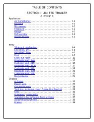
SPRINTER VANTIRE SUPPORTSince motorhomes may sit for long periods it is important to properly support the tiresif blocks are used for leveling.The CORRECT methods are shown in Figure 1. Please note that the blocks arewider than the tread and longer than the tire’s footprint. This provides maximumsupport to the tires and assures that the load is evenly distributed throughout thetire’s footprint area.CExtreme caution must be taken to ensure that the tires are fully supported when usingblocks to level motorhomes and/or RV’s. The load on the tire should be evenlydistributed on the block and in the case of duals, evenly distributed on blocks for bothtires. If not property done, the steel cables in the sidewall of the tires may be damagedand could lead to premature fatigue of the sidewall.FIGURE 1CORRECTC - 10
SPRINTER VANINCORRECTOne tire or a portion of one tire is supporting the full load.Portion of two tires are supporting the full load.CCAUTION: Tires incorrectly supported, as shown above, may be damaged whichcould lead to casing failure resulting in serious injury or property damage. If, on previousoccasions, the tires have been incorrectly supported, a hidden damage may bepresent. Please contact your local Michelin dealer and request an inspection and adetermination of possible damage.C - 11
DCAMPINGSAFETYEmergency ExitThere are three avenues of escape from the motorhome in the event of an emergency,the driver’s and passenger doors, and the side cargo door. As always, safety should beone of your top priorities. Make sure you, and everyone traveling with you, can operatethese doors and exit rapidly without light. A little planning and a quick practice sessionat each camping site is well worth the time it may take.WARNING: At each campsite make sure you have not parked in sucha manner as to block the operation of the doors or the escape avenues by beingtoo close to trees, fences or other impediments. Scenic views are one reasonfor traveling, but don’t park so the beautiful lake or steep cliff is just outsideyour doors. Do not block access to the doors from the inside or outside of thevehicle.WARNING: Read the directions carefully on the fire extinguisher. Ifthere is ally doubt on the operation, you and your family should practice, thenreplace or recharge the extinguisher. You will find your local fire department willbe happy to assist you and answer any questions.WARNING: DON’T SMOKE IN BED!KEEP MATCHES OUT OF REACH OF SMALL CHILDREN!DON’T CLEAN WITH FLAMMABLE MATERIAL!KEEP FLAMMABLE MATERIAL AWAY FROM OPEN FLAME!SMOKE ALARMOPERATION, TESTINGOPERATION: The smoke detector is operating once a fresh battery is installed andtesting is complete. When products of combustion are sensed, the unit sounds a loud85 db pulsating alarm until the air is cleared.HUSH CONTROL: The “HUSH” feature has the capability of temporarily desensitizingthe alarm circuit for approximately 7 minutes. This feature is to be used only when aknown alarm condition, such as smoke from cooking, activates the alarm. The smokedetector is desensitized by pushing the “HUSH” button on the smoke detector cover. Ifthe smoke is not too dense, the alarm will silence immediately and “Chirp” every 30-40seconds for approximately 7 minutes. This indicates that the alarm is in a temporarilydesensitized condition. The smoke alarm will automatically reset after approximately 7minutes and sound the alarm if particles of combustion are still present. The “HUSH”feature can be used repeatedly until the air has been cleared of the condition causingthe alarm.NOTE: DENSE SMOKE WILL OVERRIDE THE HUSH CONTROL FEATURE ANDSOUND A CONTINUOUS ALARM.We have all heard these warnings many times,but they are still among the leading causes of fires.Other safety information on the LPG system of your motorhome is located in thePlumbing Section of this manual.D - 1
CAMPINGCAUTION: BEFORE USING THE ALARM HUSH FEATURE, IDENTIFY THESOURCE OF THE SMOKE AND BE CERTAIN A SAFE CONDITION EXISTS.FLASHING L.E.D. LIGHT: This smoke detector is equipped with a flashing red indicatorlight. The light is located under the test button and will flash every 30-40 secondsto indicate that the smoke detector is receiving power.MAINTENANCEBATTERY REPLACEMENTTo replace-the battery remove the detector from the mounting plate by rotating thedetector in the direction of the “OFF” arrow on the cover.TESTING: Test by pushing the test button on the cover and holding it down for aminimum of 2 seconds. This will sound the alarm if all the electronic circuitry, horn andbattery are working. If no alarm sounds the unit has defective batteries or other failure.You can also test the alarm by blowing smoke into it.TEST THE ALARM WEEKLY TO ENSURE PROPER OPERATION. Erratic or lowsound coming from your alarm may indicate a defective detector, and it should bereturned for service.FALSE ALARMSSmoke detectors are designed to minimize false alarms. Cigarette smoke will notnormally set off the alarm, unless the smoke is blown directly into the detector.Combustion particles from cooking may set off the alarm if the detector is locatedclose to the cooking area. Large quantities of combustible particles are generated fromspills or when broiling. Using the fan on a range hood which vents to the outside (nonrecirculatingtype) will also help remove these combustible products from the kitchen.MODEL 0916 HAS A “HUSH” CONTROL that is extremely useful in a kitchen areaor other areas prone to nuisance alarms. For more information refer to OPERATIONAND TESTING.If the detector does alarm, check for fires first. If a fire is discovered, get out and callthe fire department. If no fire is present, check to see if other reasons may have causedthe alarm.The Model 0916 Smoke Detector uses one (1) 9-volt battery. The SMOKE DETECTORis powered by a 9V carbon zinc battery (alkaline battery may also be used). A freshbattery should last for one year under normal operating condition. This detector has alow battery monitor circuit that will cause the detector to “chirp” approximately every30-40 seconds for a minimum of seven (7) days when the battery gets low. Replace thebattery when this condition occurs. USE ONLY THE FOLLOWING 9 VOLT BATTERIESFOR SMOKE DETECTOR REPLACEMENTCarbon-zinc type: EVEREADY 216 OR 1222, GOLD PEAK 1604P OR 1604SAlkaline type: EVEREADY 522; DURACELL MN 1604, Gold Peak 1604ALithium type: ULTRALIFE U9VL. NOTE:REGULAR TESTING IS RECOMMENDED.WARNING: USE ONLY THE BATTERIES SPECIFIED. USE OF DIFFERENTBATTERIES MAY HAVE A DETRIMENTAL EFFECT ON THE SMOKE DETECTOR.NOTE: IF AFTER BATTERY REPLACEMENT, THE UNIT CONTINUES TO CHIRP,WAIT FOR APPROXIMATELY 7 MINUTES. THE “HUSH” FEATURE MAY HAVE BEENACTIVATED ACCIDENTALLY WHILE CHANGING THE BATTERIES AND WILL RESETAUTOMATICALLYDD - 2
DCAMPINGCLEANING YOUR DETECTOR:To clean your detector remove it from the mounting bracket as outlined in the beginningof this section.You can clean the interior of your detector (sensing chamber) by using your vacuumcleaner hose and vacuuming through the openings around the perimeter of thedetector.The outside of the detector can be wiped with a damp cloth.AFTER CLEANING, REINSTALL YOUR DETECTOR. TEST YOUR DETECTOR BYUSING THE TEST BUTTON.roofs, on the other side of a closed door or on a different floor. If the detector islocated outside the bedroom or on a different floor, it may not wake up a soundsleeper. The use of alcohol or drugs may also impair ones ability to hear thesmoke alarm. For maximum protection a smoke detector should be installed ineach sleeping area on every level of a home.Although smoke detectors can help save lives by providing an early warning ofa fire, they are not a substitute for an insurance policy. Homeowners and rentersshould have adequate insurance to protect their lives and property.GOOD SAFETY HABITSDEVELOP AND PRACTICE A PLAN OF ESCAPE:LIMITATIONS OF SMOKE ALARMS:WARNING: Smoke detectors are devices that can provide early warningof possible fires at a reasonable cost; however, detectors have sensing limitations.Ionization type detectors offer a broad range of fire sensing capability butare better at detecting fast flaming fires than slow smoldering fires. Photoelectricdetectors sense smoldering fires better than flaming fires. Home fires develop indifferent ways and are often unpredictable. Neither type of detector (photoelectricor ionization) is always best, and a given detector may not always providewarning of a fire. In addition, smoke detectors do have limitations. For a batterypowered detector the battery must be of the specified type, in good condition,and installed properly. AC powered detectors will not operate if AC power hasbeen cut off such as by an electrical fire or an open fuse. Smoke detectors mustbe tested regularly to make sure the batteries and the detector circuits are ingood operating condition.• Make a floor plan indicating all doors used as escape routes fromthe motorhome.• Have a family meeting and discuss your escape plan, showing everyonewhat to do in case of fire.• Determine a place outside your home where you all can meet if afire occurs.• Familiarize everyone with the sound of the Smoke Alarm and train him orher to leave your motorhome when they hear it.• Practice a fire drill at least every six months or when ever new guests arewith you. Practice allows you to test your plan before an emergency; youmay not be able to reach your children. It is important they know whatto do.Smoke detectors cannot provide an alarm if smoke does not reach the detector.Therefore, smoke detectors may not sense fires starting in chimneys, walls, onD - 3
CAMPINGWHAT TO DO WHEN THE ALARM SOUNDS:SERVICE AND WARRANTY• Leave immediately by your escape plan. Every second counts, so don'twaste time getting dressed or picking up valuables.• In leaving, don't open any inside door without first feeling its surface. If hot,or if you see smoke seeping through cracks, don't open that door! Insteaduse your alternate exit. If the inside of the door is cool, place your shoulderagainst it, open it slightly and be ready to slam it shut if heat and smokerush in.• Stay close to the floor if the air is smoky. Breathe shallowly through a cloth,wet if possible.• Once outside go to your selected meeting place and make sure everyoneis there.• Call the fire department from your neighbor’s home - not from yours!• Don't return to your home until the fire officials say that it is all right todo so.If after reviewing this manual you feel that your smoke alarm is defective in any way, donot tamper with the unit. Return it for servicing to: FYRNETICS, INC., 1055 STEVENSONCT./STE 102W, ROSELLE, IL 60172. (See Warranty for in-warranty returns).CARBON MONOXIDE ALARMThe following information is highlights from the folder provided by the alarm manufacturer.The folder, with more detailed information, is contained in your Owners’ Packet.Test detector immediately following installation and weekly for proper operationby pushing the test button until the YELLOW L.E.D. lights and a short beep is heard(approximately three seconds). Release the button. The detector will then test itself forproper operation. At completion of the self-test, the alarm will sound and both L.E.D.swill light for 3/4 of a second. The detector then resumes normal operation.DThere are situations where a smoke detector may not be effective to protect againstfire as stated in the NFPA standards 72.For instance:a) Smoking in bed;b) Leaving children home alone.c) Cleaning with flammable liquids, such as gasoline.Further information on fire safety can be obtained in a pamphlet titled “IN A FIRESECONDS COUNT” published by the NFPA, Batterymarch Park, Quincy, Mass. 02269.NORMAL OPERATIONIn normal operation the detector will flash the RED L.E.D. once every 30 seconds.WARNING CONDITIONIf the COSTAR senses a low level of CO The YELLOW L.E.D. will light and the detectorwill beep every three seconds warning that CO is present. The area should immediatelybe ventilated. A concentration of 60 PPM within 67 minutes will cause the warningcondition. Pushing the test button will silence the warning signal but the YELLOWL.E.D. will stay on. After two hours the warning signal will sound again if the CO sourcehas not been eliminated. If the condition persists there is a possibility that it may causethe unit to enter alarm condition (below). If this occurs pushing the reset button willsilence the alarm for 30 minutes.D - 4
DCAMPINGALARM CONDITIONIf the COSTAR senses unsafe levels of CO, the RED L.E.D. will light up and the alarmwill sound. The alarm condition will be signified by a repetitive alarm-sounding patternof approximately 4.5 seconds on 1.5 second off. Immediate evacuation is required.Pushing the test button will silence the alarm once for approximately 4 minutes.After approximately 4 minutes the alarm will once again sound until the unsafe COconcentration is removed.FAULT CONDITIONPeriodically the detector’s measurement circuit is tested. If an error is detected, the detectorwill sound twice and the YELLOW L.E.D. will flash twice every 30 seconds. This isan indication of circuit malfunction and that the detector requires immediate servicing.The Model 9L-1 CO Detector uses one (1) 9-volt battery. The CO DETECTOR ispowered by a 9V alkaline battery. A fresh battery should last for one year under normaloperating conditions. This detector has a low battery monitor circuit which will causethe detector to “chirp” and the red LED to flash approximately every 30-40 secondsfor a minimum of seven (7) days when the battery gets low. Replace the battery whenthis condition occurs. USE ONLY THE FOLLOWING 9 VOLT BATTERIES FOR CODETECTOR REPLACEMENT.Alkaline type: EVEREADY522; DURACELL MN1604; GOLD PEAK 1604ALithium type: ULTRALIFE U9VLNOTE: REGULAR TESTING IS RECOMMENDED.WARNING: USE ONLY THE BATTERIES SPECIFIED. USE OF DIFFERENTBATTERIES MAY HAVE A DETRIMENTAL EFFECT ON THE CO DETECTOR.MAINTENANCEBattery Replacement:CLEANING YOUR DETECTOR:To clean your detector remove it from the mounting bracket as outlined in the beginningof this section.If tamper resistant pin has been used, refer to “tamper resistant locking pin” forremoval instructions.To replace the battery remove the detector from the mounting plate by rotating thedetector in the direction of the “OFF” arrow on the cover.You can clean the interior of your detector by using your vacuum cleaner hose andvacuuming through the openings around the perimeter of the detector. The outside canbe wiped with a damp cloth.AFTER CLEANING, REINSTALL YOUR DETECTOR. TEST YOUR DETECTOR BYUSING THE TEST BUTTON.Test detector weekly for proper operation by pushing the test button until the YELLOWL.E.D. lights and a short beep is heard (approximately three seconds). Release thebutton. The detector will then test itself for proper operation. At completion of the selftest,the alarm will sound and both L.E.D.s will light for 3/4 of a second. The detectorthen resumes normal operation.D - 5
CAMPINGSERVICE AND WARRANTYIf after reviewing this manual you feel that your CO Detector is defective in any way,do not tamper with the unit. Return it for servicing to: Quantum Group, Inc., 11211Sorrento Valley Road, Suite Valley Road, Suite V. San Diego, CA 92121.device, which “burns” away impurities in the air during periods of normal use.During periods when power is interrupted, impurities can build up on the sensor.When power is returned to the detector the detector alarm may activate until theimpurities are “burned” off. This could take a number of hours, during which timethe alarm will be constantly “on”.Or call us toll free (800) 432-5599E-mail address: mktsls@qginc.comLP GAS DETECTORIn the kitchen area of your unit, approximately six inches above the floor, is the LPgas detector. LP gas is a mixture of gases produced and sold commercially as a fuelfor heating and cooking appliances. LP gas is highly flammable and, as a result, canbe explosive if ignited under certain circumstances. LP gas is heavier than air and,if confined in a closed space, will accumulate close to the floor. When the LP gasconcentration in your unit exceeds 2000 PPM the detector will provide a visual andaudible alarm by sounding a buzzer and flashing the red LED two times per second.WARNING: Activation of this detector indicates the presence of LP gas,which can cause an explosion and/or fire. This normally indicates a leak in theLP gas installation or a LP gas appliance. Extinguish all open flames, open yourwindows and door and evacuate the unit immediately. Do not activate any electricalswitch. Turn off the LP at your gas bottle(s). DO NOT RE-ENTER YOUR UNITUNTIL A QUALIFIED REPAIR TECHNICIAN HAS CORRECTED THE PROBLEM.DETECTOR TESTPress the test button for 5 to 6 seconds until the alarm sounds then release the testbutton. The red LED should flash and the alarm sound for approximately 4 minutes.This test should be performed at least once a week during normal vehicle operation,and after periods of storage, and before each trip.LOW VOLTAGEBelow 10 VDC the detector will continue to operate but will blink alternately green andorange. Below 8 VDC the unit will behave erratically and will eventually shut off. Toensure proper operation, do not operate the unit below 10 VDC.COMPONENT FAILUREThe failure of any circuit component will cause the detector to display a continuousorange LED fault light and a short beep indicating failure. If this occurs, immediatelycontact your dealer or Airstream Customer Service for the name of the nearest detectorservice center.Please read the operating instructions for your detector, which have been suppliedwith the paper work of your unit.DOPERATIONYour LP gas detector is wired directly to your vehicle battery and incorporates a 1-ampin-line fuse. When the device is operating normally the green LED will be lit.WARNING: Have a professional technician check all safety relatedsystems yearly or whenever any doubts of their ability to function properly arise.CAUTION: It is not recommended that the detector be disconnected from thebattery during periods of storage. There is a small heater on the sensor of theD - 6
CAMPINGOVERNIGHT STOPLONGER TRIPDIn time you will develop a knack for spotting wonderful little roadside locations by turningoff the main highway and exploring. There are many modern recreational vehicleparks, including State, County and Federal parks with good facilities, where you mayobtain hookups of electrical, water and sewer connections. Directories are publishedwhich describe in detail these parks and tell what is available in the way of servicesand hookups.All you need to do to enjoy the self-contained luxury is to:1. Turn on LP gas supply and light appliance pilots if required.2. Turn on water pump and open faucets until air is expelled from the system.On a longer trip, when you have stayed where sewer connections and utility hookupswere not available, it will be necessary for you to stop from time to time to dispose ofthe waste in the holding tank and replenish the water supply. Many gas stations (chainand individually owned) have installed sanitary dumping stations for just this purpose.Booklets are available which list these dumping stations.When you stop for the night, your Airstream motorhome is built to be safely parked inany spot that is relatively level and where the ground is firm. Your facilities are with you.You are self- contained. Try to pick as level a parking spot as possible.Before moving on, turn off the LP gas and water pump and lower your TV antenna.Check your campsite, both for cleanliness and to be sure you haven’t left anythingbehind. Make sure everything is properly stowed.Overnight or Weekend TripsOn overnight or weekend trips, chances are you will not use up the capacity of theholding tank, deplete the water supply, or run down the battery which supplies theliving area 12 volt current.D - 7
EXTENDED STAYMaking a long trip is not very different from making a weekend excursion. Since everythingyou need is right at hand, you are at home wherever you go. When packing for anextended trip, take everything you need, but only what you need.When you plan to stay in the same place for several days, weeks or months, you willwant your motorhome to be as level as possible. Check the attitude with a small spiritlevel set on the inside work counter. If a correction is necessary, then you must firstlevel from side to side. This can be done most easily by driving up a small ramp consistingof 2” x 6” boards tapered at both ends. WE DO NOT RECOMMEND PLACINGTIRES IN A HOLE FOR LEVELING. Check the tire section of the chassis portion of thismanual for information on tire support.Hook Up to Water by attaching a ½ “ minimum high-pressure water hose to the citywater service.CAMPINGTo use the Generator you simply start it. All switching is done automatically. The generatorcan be started from the switch above the galley. It is easier on your generatorand appliances if you’ll allow the generator to reach its normal operating speed (abouta minute) prior to applying heavy current loads.Hook your Waste Drain Hose into the Sewer Disposal Facility and attach to thedrain outlet in your motorhome. For details on this procedure see Drain and WasteSystem Section.Turn on the gas supply. Lighting a top range burner to bleed any air from the systemwill make it easier to start other appliances.When you stay for extended periods where electric or water hookups are not available,you must make regular checks on the condition of your 12-volt battery and thecontents of your water tank. Carry drinking water in a clean bucket to refill your tank.When your waste tank nears capacity, move your motorhome to a dumping location.DPlug the Electrical Cable into the City Power Service. Be sure you have the wiregrounded and have the proper polarity. See Electrical Section for technical details.A Cable/Satellite TV /Telephone Hookup is located on the outside of the motorhome.It is already wired into the existing system, so the exterior connection is allthat is required.D - 8
DCAMPINGEFFECTS OF PROLONGED OCCUPANCYYour motorhome was designed primarily for recreational use and short-term occupancy.If you expect to occupy the motorhome for an extended period, be preparedto deal with condensation and the humid conditions that may be encountered. Therelatively small volume and tight compact construction of modern recreation vehiclesmean that the normal living activities of even a few occupants will lead to rapid moisturesaturation of the air contained in the trailer and the appearance of visible moisture,especially in cold weather.Just as moisture collects on the outside of a glass of cold water during humid weather,moisture can condense on the inside surfaces of the motorhome during cold weatherwhen relative humidity of the interior air is high. This condition is increased becausethe insulated walls of a recreation vehicle are much thinner than house walls. Estimatesindicate that a family of four can vaporize up to three gallons of water daily throughbreathing, cooking, bathing, and washing. Unless the water vapor is carried outsideby ventilation, or condensed by a dehumidifier, it will condense on the inside of thewindows and walls as moisture, or in cold weather as frost or ice. It may also condenseout of sight within the walls or the ceiling where it will manifest itself as warped orstained panels. Appearance of these conditions may indicate a serious condensationproblem. When you recognize the signs of excessive moisture and condensation inthe motorhome, action should be taken to minimize their effects. For tips on controllingcondensation see the “Tips To Controlling Condensation” section.Note: Your motorhome is not designed, nor intended, for permanent housing.Use of this product for long term or permanent occupancy may lead to prematuredeterioration of structure, interior finishes, fabrics, carpeting, and drapes.Damage or deterioration due to long-term occupancy may not be considerednormal, and may under the terms of the warranty constitute misuse, abuse, orneglect, and may therefore reduce the warranty protection.To avoid condensation problems, try to follow these tips to help alleviateexcess moisture:Allow excess moisture to escape to the outside when bathing, washing dishes, hairdrying, laundering, and using appliances and non-vented gas burners.Always use the vent hood when cooking.Keep the bathroom door closed and the vent or window open when bathing and for aperiod of time after you have finished.Do not hang wet clothes in the trailer to dry.In hot weather, start the air conditioner early as it removes excess humidity from the airwhile lowering the temperature.Keep the temperature as reasonably cool during cold weather as possible. The warmerthe vehicle, the more cold exterior temperatures and warm interior temperatures willcollide on wall surfaces, thus creating condensation.Use a fan to keep air circulating inside the vehicle so condensation and mildew cannotform in dead air spaces. Allow air to circulate inside closets and cabinets (leave doorspartially open). Please keep in mind that a closed cabinet full of stored goods preventscirculation and allows the exterior temperature to cause condensation.The natural tendency would be to close the vehicle tightly during cold weather. Thiswill actually compound the problem. Simply put, you need to remove some of thewarm air, and allow some cool outside air to get inside the vehicle, so the furnace willnot recycle the humid interior air.Use fluorescent ceiling lights and minimize prolonged use of incandescent lights, whichproduce heat and contribute to condensation in the roof above the ceiling lights.D - 9
ABOUT MOLDSWhat are molds?Molds are microscopic organisms that naturally occur in virtually every environment,indoors and out. Outdoors, mold growth is important in the decomposition of plants.Indoors, mold growth is unfavorable. Left unchecked, molds break down natural materials,such as wood products and fabrics. Knowing the potential risks is importantfor any type of homeowner to protect their investment.What factors contribute to mold growth?CAMPINGProper preventive maintenance to the RV and its accessories, as described both in thismanual and in accompanying literature, will provide the best protection to the RV.For more information of controlling moisture in the RV, please read, “Tips to ControllingCondensation,” located in this manual.*If using a dehumidifier, please read and follow all manufacturer instructions and recommendationsto the use and cleaning of the dehumidifier.DFor mold growth to occur, temperatures, indoor or outdoors, must be between 40degrees and 100 degrees Fahrenheit and also have a source of moisture, such ashumidity, standing water, damp materials, etc. Indoors, the most rapid growth occurswith warm and humid conditions.How can mold growth be inhibited?By controlling relative humidity, the growth of mold and mildew can be inhibited. Inwarm climates, use of the air conditioner will reduce the relative humidity. Vents arelocated in the bathing and cooking areas and constant use is advised during foodpreparation and bathing, even during colder weather. Additionally, opening a windowduring these activities will assist in ventilation. In extremely humid conditions, the useof a dehumidifier can be helpful.*Frequent use of your RV or cleaning regularly is an important preventive measure.Further, any spills should be wiped up quickly and dried as soon as possible. Avoidleaving damp items lying about. On safe surfaces, use mold or mildew killing cleaningproducts. Check sealants regularly, and reseal when necessary to avoid water leaks.D - 10
CAMPINGWINTER TRAVELING3. Minimize use of electricity if 120-volt power source is not available.Traveling in your motorhome during the cold winter months can be a most exhilaratingexperience. There are, of course, certain precautions that must be taken as you wouldin your home in low temperatures.4. Leave cabinet doors, wet bath doors and wardrobe doors slightly open at night toallow circulation of air in and around all componentsDThe Interstate Rear Bath motorhome has 12-Volt heat pad installed with the gray/blackcombination-holding tank and the Interstate Mid Bath has the heat pad on the blacktank. The gray tank on the Mid bath model is above the floor allowing heat from thefurnace to protect it from freezing. This switch for the heating pad is located next to themonitor panel. To conserve battery power, RV antifreeze may be used to protect thegray/black tank. Battery power will last about 6 hours unless the unit is plugged into a110-volt shoreline source to operate the converter/battery charger.WARNING: Always shut off the LP gas when gasoline is added to thefuel tank.Some states do not allow LPG to be turned on while moving. While traveling in thesestates you must use your common sense. How cold is it? How long will it be beforeyou can turn the heat back on? Is the temperature dropping or rising? Remember, thewind chill factor when driving 50 MPH will cause the interior of the motorhome to coolmuch faster than when it is parked.5. Use propylene glycol type antifreeze in wastewater tank to prevent freezing.Quantity of antifreeze needed will vary with ambient temperature and the amountof liquids in tank.6. For extended stays in cold weather, insulate the water line outside the motorhome.You should remember that low temperatures in combination with high winds causean equivalent chill temperature much below what your thermometer is reading. Forinstance, with an outside temperature of zero degrees, and the wind velocity of 10miles per hour, the equivalent chill temperature is minus 20° F. The exterior waterfaucet has an in-line valve inside the motorhome. In below freezing temperatures,shut off the valve inside and open the exterior brass valve so it will drain. See thevalve section in this book for locations.1.You must have a plentiful supply of propane gas as the heat from the furnacewarms the motorhome and keeps the fresh water lines and tank from freezing.2.If your stay is longer than overnight, you should endeavor to have 120-volt electricityavailable. The house battery, fully charged, will not last more than about 15hours in freezing weather, less with use of the holding tank heating pad. Of course,you can run your generator to recharge the battery, or even use the generatorcontinually. Since the generator starts off the house battery, it is recommended tostart the generator prior to running the battery down.D - 11
The exterior of your Airstream Interstate motorhome has been painted by CarreraDesigns, a company specializing in custom recreational vehicles, with a Sherwin-Williams automotive finish. Carrera Design provides samples of the paint for minorrepairs and a use and care brochure with each motorhome as it leaves their facility. Thebrochure has a paint code sticker containing paint information.This information comes from Carrera Designs Used and Care Brochure.Following these procedures can provide a long lasting, high-gloss finish for yourrecreational vehicle. These same procedures can also be applied to your everydayautomobile, producing the same long-lasting results.Waxes and PolishesOver 90 percent of all automotive finishes are clear coat. The finish on your RV is astate-of-the-art Acrylic Urethane Basecoat/ClearCoat. This means that what you willwash and polish is a clear urethane coating designed to protect the basecoat: the pigmentedcoating that provides color. As its main function of protecting the basecoat,clearcoats need to be maintained especially in harsh environments. Clearcoats do notfade themselves, but appear to fade or lose gloss as the surface becomes contaminatedby the environment. If this contamination is not removed frequently, results willbe a dull or low gloss finish. Occasional washing alone will not adequately removesome forms of contamination and will require polishing.EXTERIORDo not use products that contain harsh abrasives such as rubbing or polishing compounds.These products should be used by experienced technicians with the propertraining and equipment. Most polishes and waxes are designed to clean and polish inone application whether by hand or machine. A machine applied polish will last longerthan one applied by hand because the high rpm buffing will create heat, resulting in adeeper wax film with higher gloss.However, a hand applied polish or wax will offer outstanding performance and protectthe RVs finish. When applying polish or wax, do so in a shaded area making surethe RV surface is at the specified temperature according to the polish manufacturersrecommendations. Due to the variations of polishes and waxes, incorporate the followingsuggestions into the polishing technique:1. Condition the polishing pad by rubbing a slight amount of polish on it.2. Use only the amount of polish specified in the label directions.3. Work a small area at a time.4. Rinse off and remove dried polish from crevices, trim and moldings.For more information, call 574 -- 295 -- 7907.EPolishes and waxes primarily served the following purposes:1. To remove minor surface imperfections caused by water spots and acid rain.2. To remove minor scratches by filling them and leveling the surface.3. To beautify the paint finish appearances with more depth and high-gloss.4. To protect the paint finish from the elements.E - 1
EXTERIORHow to Care for Your RV FinishKeeping your RV looking its best at all times involves keeping the paint finish cleanand in good condition. This means periodic washing and polishing, as well as gettingthe paint finish repaired as soon as possible when the paint is damage or affected inanyway. The purpose of the paint finish is twofold:Avoid using such items on painted surfaces, as they will damage the RV paint andfinish. Wash the wheels and wheel wells first as this removes heavy dirt and debrisand prevents it from splattering on already clean panels. Wet the entire area down toremove loose dirt and grime, hand wash one area at time using your dedicated paintfinish sponge or wash mitt. Wash from the top and work your way down, frequentlyrinsing the rinsing to minimize grit abrasion. Follow with a final rinse of water. IfE(1) Provide an aesthetically pleasing appearance.(2) To protect the vehicle from the environment. Your RV is exposed to many environmentalconditions that have an adverse effect on the paint finish:1. ROAD SALTS AND SODIUM CHLORIDE2. ROAD TAR/BUGS3. BIRD DROPPINGS/TREE SAP4. INDUSTRIAL FALLOUT/ACID RAIN/POLLUTION5. ULTRAVIOLET EXPOSURE AND MOISTUREThe most common problems resulting from these conditions are corrosion, stainingand chemical spotting. These problems can be minimized through regularly scheduledwashing and polishing.This process will remove most contamination from the RVs surface. For stubbornstains such as road tar, use an ammonia based glass cleaner or a small amount ofrubbing alcohol on a damp cloth immediately followed by warm soapy water and rinsewith clean water. This may not dissolve the road tar, but will loosen tar and bugs stainsand remove them from the surface. Do not use solvent based cleaners on bird droppingsor tree sap as these are water-based stains and will eventually dissolve using anammonia based glass cleaner, warm soapy water and a little “elbow grease”. Onceagain, after removing stubborn stains immediately rinse with clean water.Drying the RV is just as important as washing your vehicle as today’s tap water andwell water contain many chemicals that could water stain your RVs finish. We suggestusing a damp natural or synthetic chamois, however, there are other drying productssuch as lint free micro-fiber towels that work just as well.Washing your RV:Make sure the RVs surface temperature is not too hot, under 90 degrees Fahrenheit,and not in direct sunlight. A shady area is ideal for washing your vehicle as directsunlight causes water and soap to evaporate too fast, resulting in water spotting. Usea mild soap or detergent. Most auto care stores carry a car wash shampoo. Tryto avoid combination wash-n-wax products as these waxes cause buildup and aredesigned for smaller surfaces. Have two dedicated sponges or wax mitts: one forthe paint finish and one for the wheels and under carriage. Brushes or wash mittsthat have plastic bristles are acceptable for use on tires and wheel wells, but are notintended for use on the paint finish.E - 2
PRECAUTIONSCareful maintenance for the first 60 days after the paint and clear coat are applied willensure a long-lasting durable finish. Do not wax or polish for the first 60 days.First 30 days PARKING:Avoid parking under trees or near ocean salt spray.Ice or snow should not be scraped from the painted service: BRUSH OFF!If a motorhome sets more than 24 hours, remove any protective covering(bra) while not being driven.First 30 days WASHING:Commercial washes should be avoided.Wash with cold water using a mild liquid soap.Dry wiping with a drying cloth is not recommended.EXTERIORFollow the simple cautionary measures, and your new finish will give you maximumgloss and durability.Carrera Designs1101 Herman Street,Elkhart, Indiana 46516Phone: 574-295-7907Facsimile: 574-295-1547www.carreradesigns.comIt is recommended that the caulking and sealant used in external seams and jointssuch as window frames, light bezels, beltline and rub-rail molding, etc., be checkedregularly. If this material has dried out and becomes cracked or checked, or if a portionhas fallen out, it should be replaced with fresh material to prevent possible rain leaks.Caulking and sealing material is available from your motorhome dealer and most RVsupply stores.EFirst 30 days DRIVING:Gravel roads should be avoided.Antifreeze, gasoline or window solvents, if spilled on the painted serviceshould be rinse off with water immediately.Bugs or bird droppings should be rinsed off with water daily.E - 3
EXTERIORRoadside Exterior Features, Rear Bath9. Roof rack is designed limited use. 100 lbs maximum.All vents must remain clear.10. Furnace exhaust vent should be cleaned regularly.When operating furnace, be sure exhaust canescape into a well-ventilated area. Air coming fromvent can be hot, when parking the motorhome, besure to have proper clearance in venting area.ENOTE: This is a basic explanation of the location andfunction of exterior features. More in depth explanationsof certain feature’s care and maintenance isinclude in this manual in other sections.1. City Water Hook-up provides access for city waterto your fresh water system. Use ½” minimum hosefor water supply.2. Refrigerator exterior access door and vent providesaccess to the refrigerator for service and suppliesair for the cooling process. Blocking the airflowwill affect the operation of your refrigerator.3. LP Fill Door accesses the remote fill for LP gas.4. Electric Dump Valve Switch is located on the showerpanel inside the rear cargo doors. Push and holdthe switch to open the holding tank dump valve.5. Fiberglass Running Boards and fender skirts areinstalled by Airstream.6. Refrigerator exhaust vent draws air from therefrigerator access door vent across the refrigerator-coolingunit. Please keep free from obstructions.All vents should be cleaned regularly by a qualifiedservice technician.7. Radio Antenna, rubber, for living quarters entertainmentcenter. Sprinter has another antenna forthe dash unit.8. Fantastic Roof Vent, exhaust only, complete operatinginstructions are in the appliance section of thismanual. Keep all vents clear to encourage airflow.11. Sewer Hose Storage contains a sewer hose andconnector for the holding tank dump valve.12. 110 Volt Power Cord Inlet, 30-amp service is required,power cord is stored inside rear cargo doorsin a plastic storage compartment.13. Cable/Satellite TV/Telephone Jack is a weatherproofmodule pre-wired for cable TV and telephonereception. A portable satellite dish can also be usedin the cable connection.14. Holding Tank Outlet w/Electric Dump Valve is todrain gray/black combination tank. Remove sewerhose from storage compartment, uncap valve outlet,hook hose connector to dump valve bayonet ring.Be sure end of hose is inserted into sewage tankand push/hold remote switch located inside the rearcargo doors.E - 4
EXTERIORCurbside Exterior Features, Rear BathENOTE: This is a basic explanation of the location andfunction of exterior features. More in depth explanationsof certain feature’s care and maintenance is include inthis manual in other sections.1. Water Fill w/Lock is used to fill the fresh water tank.Use only clean fresh potable water.2. Exterior Shower can be used on the water pump orwith the city water hook up.3. Porch Light is switched just inside the side cargodoor.4. Electronic Ignition Water Heater Door and Vent is partof the plumbing system. The intake vent, drain plugand exhaust vent are located inside this door. Regularmaintenance by a qualified service technician is requiredto keep the water heater operating efficiently.5. Patio Awning operating and care instructions areincluding in another section of this manual.6. TV Outlet/12 Volt Outlet provides reception for an exteriortelevision. It is pre-wired and integrated into theCable TV/Satellite TV system. There is also a 12 Voltcigarette-style outlet for a 12 volt operated television.7. Power Boosted TV Antenna is wired into TV outletson exterior of coach and inside unit at entertainmentcenter cabinet.8. Holding Tank Vent provides a vent for the black/gray combination tank.9. Exterior 110 Volt Outlet provides an exterior GFIprotected electrical source.E - 5
EEXTERIORRoadside Exterior Features, Mid BathNOTE: This is a basic explanation of the location andfunction of exterior features. More in depth explanationsof certain feature’s care and maintenance isinclude in this manual in other sections.1. City Water Hook-up provides access for city waterto your fresh water system. Use ½” minimum hosefor water supply.2. Refrigerator exterior access door and vent providesaccess to the refrigerator for service and suppliesair for the cooling process. Blocking the airflowwill affect the operation of your refrigerator.3. LP Fill Door accesses the remote fill for LP gas.4. Cable/Satellite TV/Telephone Jack is a weatherproofmodule pre-wired for cable TV and telephonereception. A portable satellite dish can also be usedin the cable connection.5. Fiberglass Running Boards and fender skirts areinstalled by Airstream.6. Refrigerator exhaust vent draws air from therefrigerator access door vent across the refrigerator-coolingunit. Please keep free from obstructions.All vents should be cleaned regularly by a qualifiedservice technician.7. Radio Antenna, rubber, for living quarters entertainmentcenter. Sprinter has another antenna forthe dash unit.8. Fantastic Roof Vent, exhaust only, complete operatinginstructions are in the appliance section of thismanual. Keep all vents clear to encourage airflow.9. Roof rack is designed limited use. 100 lbs maximum.All vents must remain clear.10. Furnace exhaust vent should be cleaned regularly.When operating furnace, be sure exhaust canescape into a well-ventilated area. Air coming fromvent can be hot, when parking the motorhome, besure to have proper clearance in venting area.11. Roof AC12. Sewer Hose Storage contains a sewer hose andconnector for the holding tank dump valve.13. Exterior Shower can be used on the water pumpor with the city water hook up.14. Holding Tank Vent provides a vent for the black/gray combination tank.15. Fresh Water Low Point Drain Lines are locatedunder the unit just inside the floor board. Manualdump valves for the main and auxilliary holdingtanks are also located in this area. Remove sewerhose from storage compartment, uncap valve outlet,hook hose connector to dump valve bayonet ring.Be sure end of hose is inserted into sewage tank. Itwill help to flush the sewer hose if the main tank isopened first and then the auxillary tank.110 Volt Power Cord Inlet, 30-amp service is required,power cord is stored inside rear cargo doors in aplastic storage compartment.E - 6
EXTERIORCurbside Exterior Features, Mid BathNOTE: This is a basic explanation of the location andfunction of exterior features. More in depth explanationsof certain feature’s care and maintenance is include inthis manual in other sections.1. Water Fill w/Lock is used to fill the fresh water tank.Use only clean fresh potable water.4. Patio Awning operating and care instructions areincluding in another section of this manual.5. TV Outlet/12 Volt Outlet provides reception for an exteriortelevision. It is pre-wired and integrated into theCable TV/Satellite TV system. There is also a 12 Voltcigarette-style outlet for a 12 volt operated television.E2. Porch Light is switched just inside the side cargodoor.6. Exterior 110 Volt Outlet provides an exterior GFI protectedelectrical source.3. Electronic Ignition Water Heater Door and Vent is partof the plumbing system. The intake vent, drain plugand exhaust vent are located inside this door. Regularmaintenance by a qualified service technician is requiredto keep the water heater operating efficiently.7. Power Boosted TV Antenna is wired into TV outletson exterior of coach and inside unit at entertainmentcenter cabinet.8. Holding Tank Vent provides a vent for the black/graycombination tank.E - 7
EXTERIORPATIO AWNINGOPERATION1. TO EXTEND AWNING:C. Unlock flipper latch located on the support arm. Slide arm outward until the armis released from the support arm catch. Swing the arms downward and out of thelead rail.A. Adjust the crank handle to the required length. To adjust the crank handle,twist the locking knob on the crank counter-clockwise to loosen. Extendbottom portion of the crank assembly outward or retract inward to matchthe required length. Twist the locking knob clockwise to tighten the crankassembly. The crank is stored on the curbside lounge access door.ED. Adjust the support arm to the requiredheight and fasten by pulling up on the flipperlatch.B. Hook the end of thecrank handle into thegear assembly loop of theawning assembly. Turnthe crank counter- clockwise.Crank the awningout far enough to gainaccess to the secondarysupport arms.E - 8
EXTERIORE. Unroll the awning completely movingthe support arms each time whennecessary.2.TO RETRACT AWNING:A. Remove the support arms from the bottom bracket,or remove the ground stake if in the carport position.B. Slide the support arms together and pivot them intothe lead-rail for storage by reversing Step 1C on theprevious page.F. To use the carport position, drive ground stakes through the holes in the carportfoot and into the ground for support. CAUTION. GROUND STAKES WILL NOTPREVENT THE AWNING FROM MOVING IN THE WIND!G. To use the bottom brackets, swing each arm toward thevehicle, lift the bracket pin and position foot into bracket andthen release the pin.C. Hook the end of the crank handle into the crankloop of the awning assembly. (Right) Roll fabric upby turning the crank handle clockwise, or opposite ofwhat was done to extend the awning. Roll awning upuntil the lead rail is completely retracted into the case.CAUTION: THE FABRIC MUST ROLL UNDERNEATHTHE ROLLER TUBE! ROLLING THE FABRIC OVERTHE ROLLER TUBE WILL BLOCK THE GEAR BOXFROM PROPERLY RETRACTING!3.AWNING USE IN WIND AND RAIN.To prevent water build up on the awning, position one upper arm substantially lowerthan the other to create enough of a slope for adequate water run off.EH. Turn crank until awning is all of the way out. Turn the crank back a partial turn tobackwind the awning slightly. This tightens the fabric.NOTE: IF WIND OR EXTENDED PERIODS OF RAIN ARE EXPECTED, ROLL UPTHE AWNING AND SECURE FOR TRAVEL!CAUTION: THE EFFECTS OF WINDAND RAIN ON ANY AWNING AREUNPREDICTABLE. SEVER DAMAGE TOTHE VEHICLE AND OR THE AWNINGMAY RESULT AND CANNOT BECOVERED BY WARRANTY!E - 9
EXTERIORCARE AND MAINTENANCE1. CARE OF FABRICA. VINYL FABRIC. Mildew will not form on the awning material itself, but may formon the dust allowed to accumulate on the canopy. A mild detergent (soap & water)will keep your awning looking new. Once cleaned make sure the awning is rinsedthoroughly and is dried before storing. DO NOT USE BLEACH!B. ACRYLIC FABRIC. A mild detergent (soap &water) should be used to clean theacrylic canopy. Rinse thoroughly and allow the canopy to be dried before rolling upEthe awning.CAUTION. DO NOT USE BLEACH, CAUSTIC CLEANERS OR METAL CLEANERSON ACRYLIC AS THEY WILL CA USE PERMANENT DAMAGE TO FABRIC!2. PERIODIC MAINTENANCELike any other part of the RV, an owner should periodically inspect the awning. Thefollowing items should be checked.A. All mounting brackets are tight.B. Check all pivot points for enlargements of holes or broken rivets.C. Check end caps for cracking, splitting.D. Check that awning rail is tight against coach and all screws are tight.E. Check canopy for loose stitching and possible shrinkage or puckering.E - 10
INTERIORThe interior of your Airstream motorhome has been designed to take a limited amountof space and provide you with all the comfort, convenience, durability and appearancepossible. An understanding of the operational procedures and maintenancetechniques of the interior appointments will add to your pleasures, as well as to thelong life of your motorhome.LoungesThe glass doors on the entertainment center must be cleaned with a anti-staticcleaner and cloth. Windex or common ammonia products will damage the coatingon the surface.CAUTION: Do not use any abrasive material. Abrasive cleaners, cloths and padsshould not be used, as there is the possibility it could scratch the surface. Aprotective pad should always be placed under hot utensils.To convert the lounges into a bed, grasp the front edge of the seat, pull straight upand pull it toward the aisle of the motorhome. The backrest will slide down into placeautomatically. Extending both sofas form a double bed.DinetteThe pedestal table is stored under the passenger side lounge on a shelf. Open the aisledoor for access. Insert the two stands into the top and then the insert the table into thepedestal braces in the aisle way.Wet BathTo clean your ULTRA/GLAS shower stall unit, use warm water and one of the strongerliquid detergents. Do not use abrasive cleaners; they may scratch and dull the surfaceof your ULTRA/GLAS unit. Stubborn stains can be removed with solvents such asturpentine, paint thinner or acetone. Restore dulled areas by rubbing with an automotive-typeliquid cleaner, and then put the soft glow back into your ULTRA/GLAS unitwith a light application of liquid wax.FVinyl FloorThe vinyl floor in your unit can be cleaned with liquid floor cleaning solutions recommendedfor vinyl floors and warm water.CAUTION: Warn occupants of the vehicle when fresh wax has been applied, justlike a home, the floor will be slippery.Cabinets/Overhead Lockers/Counter areasThe furniture is manufactured from of a high-pressure laminate and can be cleanedwith soap and water, or you can use a common solvent on tough spots. Furniturepolish can be used sparingly.F - 1
FINTERIORINTERIOR (cont)SinkCleaning can be accomplished using mild liquid detergent with a soft cloth. Rinsecarefully and dry. Silver polish will leave spots that cannot be removed. A completeHome Owners Guide for your sinks is supplied in your Owner’s Folder. Please readthese instructions before use.Metal Interior SkinThe metal interior skin is coated with a baked on acrylic coating. Use soft rags or washmitts always moving lengthwise with the grain of the aluminum. NEVER rub hard onthe coating. Oil, grease, dust and dirt may be removed by washing with a 5% solutionin water of commonly used commercial and industrial detergents. Cleaning should befollowed by a thorough clean water rinse. Drying the metal with a chamois or a softcloth may prevent spots and streaks. WHEN WASHING OR WAXING THE METAL,ALWAYS WIPE “WITH” THE GRAIN OF THE METAL.After cleaning and drying, a good grade of nonabrasive automotive paste or liquid waxonce a year will increase the life of the finish and help remove minor scratched andabrasions. It will also protect the metal from minor scratches and make subsequentcleaning easier.If a substance is found on the coating that cannot be removed by normal washing procedures,Airstream recommends using DX 330 Acryli-Clean made by PPG Industries.Follow all directions and warnings on the product container. Acryli-Clean should beused by trained personnel only, using the proper equipment under controlled conditions.Use the Acryli-Clean as sparingly as possible to remove oil or grease. Rinse withcool water immediately after use.CAUTION: ABRASIVE POLISHES OR CLEANING SOLVENTS ARE TOO STRONGAND SHOULD NEVER BE USED. RINSE ALL GRIT FROM SURFACE PRIOR TOWASHING. Use soft rags or wash mitts always moving lengthwise with the metal.NEVER rub hard on the coating. Even the softest rag will damage the coating ifexcessive pressure is applied.Fabric CleaningUse an automotive upholstery shampoo product or the foam from a mild detergent.With either method, pretest a small area before proceeding. Use professional furniturecleaner when an overall soiled condition is reached.Front Privacy DrapeUnsnap the drapes to remove. Wash on gentle cycle.ShadesNightshades are lowered and raised by the bars running across the shade. Grasp inthe center of the bar or place hands evenly on the bar. Pull the bottom bar up or downto open or close the shade. Rough roads and long trips may cause the pleated shadesto move slightly during travel. Tensions on the strings at the sides of the shades adjustthe ease of operation and their ability to stay up during travel. Do not over-tighten asthis may cause the string to break, requiring service.A feather duster or the soft-bristled brush often found as part of vacuum cleaner attachments,are recommended for cleaning the pleated shades. The longevity of thepleated shades will be increased if the shades are closed, glass shows, when yourvehicle is stored.F - 2
LPG SYSTEMYour motorhome is equipped with a permanentlymounted tank for LPG (Liquid Petroleum Gas) with aremote fill. LPG burns with a clean blue flame. Thereare two basic types of LPG in common usage: Butaneand Propane. Butane is widely used where temperaturesare normally above freezing the year round, andPropane is used where subfreezing temperatures arecommon, since Butane freezes at 32°F as comparedto -40°F for Propane. ALL OF THE ORIFICES IN THELPG APPLIANCES ARE OF THE UNIVERSAL TYPETHAT WILL BURN EITHER FUEL. How long a full tankof gas will last is dependent on usage. In cold weather,when you are using the furnace, large amounts of hotwater, and cook extensively, you will naturally use morethan you will in warm weather, when you may do limitedcooking. On the average, with normal cooking andother appliance use, you can probably count on two tofour weeks of usage from the tank.If you have allowed the tank to run out, air may havegotten into the lines. In this event the air must be forcedout through the lines by gas pressure before you canlight the pilots. Hold a match to the pilot of the applianceclosest to the tanks until it lights and stays lit.Then move to the next closest, etc.PLUMBINGLP TANK REMOTE FILLThe LP tank in filled by accessing the remote fill hookup located inside the LP Fill Door on the roadside ofthe vehicle. Be sure the fill is free of dirt. It may help toremind your LP supplier to only use a clean fill hose tofill your tank.WARNING: Only certified LP suppliersshould fill the LP Tank. Turn remote gas supplyswitch off before filling or refilling LP tank.REMOTE GAS SUPPLY SWITCHA remote switch for shutting off the gas to all appliancesis located inside this compartment. The switchactivates an electric solenoid that opens and closes,shutting the gas off at the tank. The switch rotates ¼turn. This switch should be turned off during the fillingof the LP tank. NOTE: The electric gas shut-offsolenoid closes automatically when 12-volt power isdisconnected. It will reopen when power is restored.WARNING: All pilot lights and appliancesmust be turned off during refueling of motorhomefuel tank and permanently mounted LPG tank.Gas lines should be checked periodically for leakswith ammonia free soapy water.Do not use open flame. If gas can be smelled, appliancepilots fail to stay on, or any other abnormalsituation occurs, use the remote supply switch toshut off the tank valve immediately and call on aqualified LPG service center or Airstream ServiceCenter.CAUTION: Moisture in the LPG tank will cause a malfunctionof the regulator in controlling proper pressure.This may result in the flame lifting off the burner, or theGG - 1
PLUMBINGflame may go out frequently. Many refueling stations will add approximately ¼ to ½gallon of alcohol to lower the moisture temperature. Moisture will then pass throughthe regulator without the formation of ice crystals.A warning label has been located in the cooking area to remind you to providean adequate supply of fresh air for combustion. Unlike homes, the amount ofoxygen supply is limited due to the size of the recreational vehicle, and properventilation when using the cooking appliances will avoid dangers of asphyxiation.It is especially important that cooking appliances not be used for comfortheating as the danger of asphyxiation is greater when the appliance is used forlong periods of time.LPG RegulatorThe LPG regulators used on Airstream motorhomes are designed for low-pressure service,with a normal outlet pressure setting of 11.5 inches water column. Only personneltrained in the proper procedures, codes, standards, etc., should service regulators.Have the regulator inspected each time the tank is refilled.Replace any regulator that has had water in the spring case, or shows evidence ofexternal corrosion, or corrosion inside the spring case. Closely examine regulatorsdirectly connected to the container valve by means of a solid POL adapter (horizontalmounting) for signs of corrosion. (An Airstream Service Center is recommended forthis service.)Portable fuel burning equipment, including wood and charcoal grills and stoves,shall not be used inside the recreational vehicle. The use of this equipment insidethe recreational vehicle may cause fires or asphyxiation.A Warning Label has been located near the LP gas container. This label reads:DO NOT FILL CONTAINER (S) TO MORE THAN 80% PERCENT OF CAPACITY.Overfilling the LP gas container can result in uncontrolled gas flow that cancause fire or explosion. A properly filled container will contain approximately 80percent of its volume as liquid LP gas.Do not bring or store LP gas containers, gasoline or other flammable liquidsinside the vehicle because a fire or explosion may result.GBASIC RULES FOR SAFETYWARNING:DO NOT store LP containers within vehicle. LP containers are equipped withsafety devices that vent gas should the pressure become excessive.DO NOT use cooking appliances for comfort heating. Cooking appliances needfresh air for safe operation. Before operation open overhead vent or turn onexhaust fan and open window.G - 2
PLUMBINGGas Regulator Removal/ReplacementWARNING: If you smell gas:1. Extinguish any open flames, pilot lights and all smoking materials.2. Do not touch electrical switches.3. Shut off the gas supply at the tank valve(s) or gas supply connection.1. Shut off main gas supply at the tank.2. Remove the plastic protective cover from the regulator assembly3. Using two wrenches, one to hold the line fitting and one to turn the flare nut,disconnect the regulator from the flexible rubber line.4. Open doors and other ventilating openings.4. Disconnect the regulator from the tank fitting. Remove regulator.5. Leave the area until odor clears.5. To replace, reverse the removal procedures.6. Have the gas system checked and leakage source corrected before using again.LP gas regulators must always be installed with the diaphragm vent facingdownward. Regulators that are not in compartments have been equipped with aprotective cover. Make sure that regulator vent faces downward and that coveris kept in place to minimize vent blockage that could result in excessive gaspressure causing fire or explosion.GThe regulator at the L.P. tank is under a gray plastic cover. The protective cover certainlyhelps to keep the vent on the regulator from being clogged by wasps or ice, butshould still be checked regularly to make sure the vent remains clear.WARNING: Do not attempt to seal regulator cover.WARNING: Check vent each time tank is filled to make sure it is clearof obstructions.G - 3
PLUMBINGGWATER SYSTEM - SELF-CONTAINEDThe fresh water system consists of a city water hook up, fresh water tank fill, freshwater tank and drain valve, water-pump, pump filter, hot and cold water lines, waterheater, fresh water line drain valves, and faucets.To operate the system:Turn the water heater by-pass valves to normal flow position.The by-pass valves are located under the galleycabinet, and are accessed by opening thelower door.For normal operation open valves A and C andclose valve B. (Reverse the valves and drain thewater heater for winterization).Check all drain valves and turn them to theclosed position as needed.Fill the water tank by opening the exterior door marked water fill, remove screw capand pull the vent plug. A garden hose can now be inserted or use a clean bucketand funnel to fill the tank. It’s a good idea to let the water run through the hose for ashort time to flush it out. RVers sometimes fill their tanks with “home” water to avoidstrange water that may be distasteful to them on short outings. Remember the morewater you carry in the fresh water tank, the less cargo carrying capacity you have forother items.Open the hot side of the galley, wet-bath, or exterior shower faucet and fill the waterheater by turning on the water pump switch or by connecting to an exterior city watersource. For some time the open faucet will only sputter. This is because the waterheater is being filled and air is being pushed out through the lines. Once the waterheater is full, a steady stream of water will come from the faucet. CAUTION: Dooperate the water heater until it is full of water. Now open a cold faucet. It willsputter for a short time, but will soon expel a steady stream. All other faucets can nowbe opened until all air is expelled.Once the system is filled with water and the faucets are closed, the water pump willshut off.CAUTION: To prevent equipment damage the water heater should only bestarted after the water system is primed and ready for use.When a faucet is opened the pump will come back on automatically. If the faucet is justbarely open it is normal for the pump to cycle on and off rapidly.It is normal for a pump to occasionally cycle when all faucets are off to keep the waterpressure at the set point. However, if it cycles frequently (more than a few times anhour) the plumbing system and pump should be checked to be sure it is not loosingpressure through a slow water leak or back through the pump.CAUTION: Turn the water pump off when the motorhome is left unattended.The amount of water in the tank may be checked on the Monitor Panel, or you may fillthe tank until water overflows out of the fill.G - 4
PLUMBINGWATER PUMP AND STRAINERManufacturer:Shur-Flo1740 Markle StreetElkhart, Indiana 46514Phone: 219-294-7581When reassembling only rotate the inlet side of thestrainer until the stops are felt. The “O” ring performsthe sealing and too much pressure will only breakthe strainer.CAUTION: The Sureflo water pump should beturned off when hooked to city water.a container of water.3. Pour the solution (water/bleach) into the tank and fillthe tank with potable water.4. Open all faucets (Hot & Cold) allowing the water torun until the distinct odor of chlorine is detected.The water pump and strainer are located inside therear cargo door on the Rear Bath Model. The Mid Bathmodel has the pump under the galley and can be accessedby opening the lower galley door. The strainershould be visually checked for accumulation of sandor debris that could affect water flow.SANITIZINGPotable water systems require periodic maintenanceto deliver a consistent flow of fresh water. Dependingon use and the environment the system is subject to,sanitizing is recommended prior to storing and beforeusing the water system after a period of storage.Systems with new components, or ones that have beensubjected to contamination, should also be disinfectedas follows:1. Use one of the following methods to determine theamount of common household bleach needed tosanitize the tank.5. The standard solution must have four (4) hours ofcontact time to disinfect completely. Doubling thesolution concentration will allow for contact time ofone (1) hour.6. When the contact time is completed, drain the tank.Refill with potable water and purge the plumbing ofall sanitizing solution.NOTE: The sanitizing procedure outlined above is inconformance with the approved procedures of RVIAANSI A 119.2 and the U.S. Public Health Service.GTo clean the strainer screen, first remove the inlet connectionfrom the pump side of strainer. This will allowthe intake side of the strainer to be rotated about 1/8turn counter clockwise and be removed. The screenpart of the strainer will now be accessible for cleaning.A) Multiply “gallons of tank capacity” by0. 13; the result is the ounces of bleachneeded to sanitize the tank.B) Multiply “Liters of tank capacity” by 1.0;the result is the milliliters of bleach neededto sanitize the tank.2. Mix into solution the proper amount of bleach withinG - 5
PLUMBINGCITY WATER HOOKUPUse a high-pressure hose of at least ½ “ diameter. It should be a tasteless, odorlessand non- toxic hose designed for RV use. The city water inlet is a standard gardenhose thread. We suggest you carry two lengths of hose.CAUTION: The Sureflo water pump should be turned off when hooked to citywater.Your plumbing system has a built in pressure regulator to protect your lines and faucetsfrom extremely high pressures on some city water systems. An after-market externalregulator is not recommended, as it could lower the water pressure at the inlet andthus to your faucets and shower.Exterior ShowerGThis way you have the ability to reach hookups further away than normal, plus youhave a spare hose should one fail or become damaged unexpectedly. Be sure to turnthe water heater bypass to the normal flow position as described under the WaterSystem Self-Contained part of this section so it will fill.After hooking up the hose and turning on the city water valve provided in the park,slowly open a faucet. There will be a lot of spurts and sputtering until all the air isexpelled from the motorhome system. If the water heater is empty it will take sometime before all the air is expelled and you get a steady flow of water at the faucet. Oncea steady flow is achieved at one faucet, the others should be opened long enough toexpel the air in the lines going to them.An exterior shower is provided for your convenience. Be sure to drain the hose andopen the valves before opening the low point drain lines for winterization.G - 6
PLUMBINGGALLEY FAUCETCare InstructionsMODEL 67315CManufacturer:As with any fine polished surface, your faucet will retain its shine for years to come withproper care. The LifeShine finish on the faucet does not require the extraordinarywork needed to maintain most fine polished brass finishes.United StatesCanadaMoen IncorporatedMoen Inc.25300 Al Moen Drive 2816 Bristol CircleNorth Olmstead, OH. 44070-8022Oakville, Ontario L6H5s7www.moen.comBe sure to read and follow usage instructions enclosed any scour pad or scrub spongebefore use.• CAUTION: Do not use pads or sponges that specifically do not recommenduse for cleaning polished services.For US customer service, warranty, and a local parts outlets contact Moen at 1-800-BUY-MOEN (289-6636).For Canadian service contact: Toronto 905-829-3400,Rest of Canada 1-800-465-6130• CAUTION: Many pads or sponges with green fibrous surface (such asScotch-Brite heavy duty scrub sponges) contain microscopic mineralparticles that can scratch nearly all polished services, including thisfaucet finish.The LifeShine finish can be cleaned with most household cleaners (including mildabrasives), when used according to their manufacturers instructions for use.• Rinse any strong cleaners off immediately after used to maintain theLifeShine finish luster.GMild scrubbing with fine steel wool (0000 grade) can remove build up dirt orwater stains.Visible water spots on this highly lustrous and reflective finish can be easily wiped offwith a cloth dampened with water or with glass cleaner.G - 7
PLUMBINGGALLEY FAUCETSERVICECAUTION: Always turn water OFF before remov-3. Pry out retainer clip (14) with flat bladed screwdriver.To Correct reversed Hot and Cold Positions:ing existing faucet or disassembling the valve. Open(It is necessary to shut off water supplies)Gfaucet handle to relieve water pressure and ensure thatcomplete water shutoff has been accomplished.4. Grasp cartridge stem with a pair pliers and pullcartridge (15) straight up and out of body.1. Position handle so that it points toward you.Remove handle (follow instructions for SERVICE1. Remove red/blue plug bottom (3) from front ofReinstall has follows: Install cartridge (15) into valvestep 1 only).lever handle, remove screw (2) and lever handlebody with notched flat on stem facing forward. Be sure(1). Unscrew handle screw (4) and lift off the handleto position the ears of the cartridge in the front and2. Turn cartridge stem so that the notch is turned ½adapter (5) (with handle connector (6) attached).back. Reinstall the retainer clip (14) that straddles theturn or 180 degrees.ears on the cartridge. Continue reassembly by revers-2. Unscrew collar (9) being careful not to damageing the steps discussed in steps 1-3.3. Reinstall handle following SERVICE instructions.the finish, lift out pivot retainer (10). Unscrew theretainer nut using channel locks and remove theNote: To service vacuum breaker assembly, (anti-si-O-ring (12) and bearing washer (13). Remove wash-phon protection) the hose must be disconnected fromers (7) and (8) from the cartridge stemthe threaded discharge prior to removing the spoutreceptor (20).G - 8
PLUMBINGDRAIN VALVE LOCATIONSThe fresh water system has three drain valves.On the Rear Bath the drain valves are accessible by opening the rear cargo doors.There are two low point water line drain valves and the fresh water tank drain valvelocated in this area.On the Mid bath model the fresh water tankk drain valve is located by the water pumpunder the galley. The hot and cold water lines drain valves are located under the motorhomeon the roadside just behind the floor board and in front of the holding tankdump valves.GG - 9
PLUMBINGTOILETManufacturer:Canada:Thetford CorporationThetford Sanitation Ltd.7101 Jackson Road 2710 Slough StreetAnn Arbor, MI 48103Mississauga, Ontario313-769-6000 Canada, L4T 1G3The RV toilet in your Airstream is a design that has been used for many years. In normaluse, when you are hooked up to city water, both pedals are depressed together. Thisdumps the sewage and flushes fresh water down the side of the bowl. Water willcontinue to run into the bowl for a short time after the pedals are released. When youwish to conserve water hold the hand-spray head over the bowl and hold down thethumb-operated lever. Now when you depress the pedal all the water is routed throughthe hand-spray.REMEDY- Insert the end of a coat hanger or similar object into the sealing groove andremove the foreign material. Avoid damaging the rubber seal while cleaning.PROBLEM: Toilet leaks. There is water on the floor. Specify the problem.Determine if water is leaking from:CAUSE:a. Vacuum breaker.b. The water-control valve.c. Bowl to mechanism seal. (If this is the problem, the waterwould not stay in the bowl.)d. Closet flange base seal.GCAUTION: When you dump the bowl of the toilet make sure all paper and solidshave cleared the slide mechanism before you allow it to close. Failure to do socan cause the groove for the slide to become jammed and the slide will no longerclose completely.If the problem should occur, a small nail or bent clothes hanger can be used to “pick”the material out of the groove.TROUBLE SHOOTINGPROBLEM: Water keeps running into bowl.CAUSE: The blade in the bottom of the bowl is not closing completely, which in turnkeeps the water control valve partially open. The groove into which the blade seatswhen completely closed is clogged with foreign material.REMEDY:a. The vacuum breaker. If the vacuum breaker leaks whenflushing the toilet, replace vacuum breaker.b. If the vacuum breaker leaks when the toilet is not in operation,replace the water control valve.c. Leaks at the bowl to mechanism seal. Remove mechanismand replace seal,d. Leaks at closet flange area. Check front and rear closet flangenuts for tightness. If leak continues remove the toilet, checkthe closet flange height. The height should be between ¼“and 7/16“ above the floor. Adjust closet flange heightaccordingly and replace closet flange seal.G - 10
PLUMBINGPROBLEM: Foot pedal operates harder than normal or the blade sticks.3. Depress pedal and remove nut located in pedal recess.REMEDY: a. Apply a light film of Silicone spray to blade.b. Check closet bolt tightness. If closet bolts are over tightened,the mechanism may be distorted.PROBLEM: Bowl will not hold water; i.e., water leaks from bowl down into theholding tank.4. Reach behind toilet and remove nut on opposite side of base from pedals. In somesituations you may want to remove the plug in top of the seat designed to giveaccess from above to this nut.NOTE: Always replace flange seal when toilet has been removed.WinterizingREMEDY: Using a bent screwdriver or similar object, scrape the groove infront of the mechanism blade. Generally paper or other foreignmaterial is lodged in this groove, causing the leak.CAUTION: Use care not to damage the blade seal. Always make certain that the toolis under the lip of the seal, not above it.The tool can easily be made by bending a coat hanger or screwdriver over about 7/8”.MAINTENANCEIf the bowl-sealing blade does not operate freely after extended use, it may be restoredto its original, smooth operating condition by applying a light film of silicone sprayto the blade. To clean the toilet use Thetford Aqua Bowl or any other high grade,non-abrasive cleaner. Do not use highly concentrated or high acid content householdcleaners. They may damage the rubber seals.Draining MethodDisconnect water supply line at water valve. Completely drain the water supply linebefore winter storage.CAUTION: To avoid damage, when using air pressure to blow water from thelines, be sure toilet valve is in the open position.CAUTION: If water is frozen in the toilet, do not attempt to flush until with theice thaws.CAUTION: Never use automotive type antifreeze.For Thetford service centers: USA 1-800-521-3032Canada: 1-888-215-5410GREMOVAL1. Shut off water valve behind toilet or main water supply.2. Disconnect water supply line from toilet. You will probably find a small mirrorvery useful.G - 11
PLUMBINGSTORAGE AND WINTERIZINGWhen storing your motorhome for a short or long period, use the same precautions asyou would in your own home in regard to perishables, ventilation and rain protection.In addition, for prolonged storage periods flush out all the drain lines and the holdingtank. Also, drain the entire water system, including the water heater and the freshwater storage tank. Instructions for draining the water system are explained in thefollowing paragraphs on winterizing.Twice a year, or after a long storage period, we suggest you take your unit into yourAirstream dealer for a check-up and cleaning of the gas operated appliances.5. While the water is draining from the system, depress hand spray thumb button on thetelephone showerhead and drain all the water. Unscrew the head on spray unit andstore. Remove, drain, and store the exterior water service hose and showerhead.6. After the water has stopped running from the drain lines, fresh water tank, and waterheater, apply at least 60 lbs. of air pressure at the city water inlet. Be sure the toiletvalve and all drain valves and faucets are open and pump outlet hose is disconnected.This can be accomplished at a service station. The goal is to force anyremaining water from the water heater and remove any water that may be trappedin low areas.GThe main consideration in winterizing is to guard against freezing damage to the hotand cold water systems, the waste drain system (including the traps), the waste holdingtanks, the water heater and the battery. To completely winterize your motorhomefollow this procedure:1. Level the motorhome from side to side and front to rear. Open the hot and coldwater valves on the exterior water service, lavatory and wet bath.2. Turn the water pump switch to the OFF position or/and disconnect city water.3. Open low point valves for the hot and cold water lines and the fresh water tank drainvalve. On the Rear Bath model they are located inside the rear cargo doors. On theMid Bath model the tank drain is located under the galley and the water line drainvalves are under the motorhome in front of the dump valves. One drain valve or plugis located on the water heater exterior and is accessible through the water heateraccess door. Remove this plug and allow water to drain. See drain valves and theiraccess in this section.4. Follow winterizing instructions for your toilet in the toilet section of this manual.7. Pour a cup of non-toxic antifreeze into the wet bath and galley sink drains to preventfreezing water in traps.8. Be sure to open the holding tank valve, and drain and flush the tank thoroughly. (Thisis very important, as the frozen sewage could seriously damage the tank.)9. Remove the house battery from your motorhome and store in a cool dry place wherethere is no danger of freezing. It is very important for optimum life of your batteryto check it periodically and to keep it fully charged. This is especially true in wintermonths, when the temperature may drop below freezing. If the period of storageis for 30 days or less, you may turn off the battery disconnect switch rather thanremove the battery. Continue to check and recharge the battery as needed, at leastweekly in severe weather.10. Remove any items (food, cosmetics, etc.) from the interior that might be damagedby freezing, or might damage the motorhome if containers break.Daimler/Chrysler recommends disconnecting the engine battery if the vehicle is storedfor a long duration. Always disconnect the and connect the ground first. If you removethe battery, follow the same storage tips as explained for the house battery.G - 12
PLUMBINGSTORAGE AND WINTERIZING (continued)For additional winterizing protection, add non-toxic antifreeze (approved for drinkingwater systems) to your water lines using the following procedure:1. Reconnect all lines except the hose to the pump inlet port. Close all drain valves(See Step 3)*2. Turn bypass valves to bypass position.3. Attach a length of hose to the pump inlet port. This piece of hose should be longenough for the free end to be inserted into and reach the bottom of the antifreezecontainer.*The by-pass valves are located behind the galley cabinet lower door on the Rear Bathmodel and under the passenger side lounge on the Mid Bath model.To access the valves on the Mid Bath model, the recessed panel between the loungedoors must be removed. Snap the caps off the four screws, remove the screws, anduse the finger hole in the panel to slide it out.Turn the water heater valves to by-pass flow position. To by-pass the water heaterfor winterizing, close valves A and C and open valve B (See illustration). For normaloperation open valves A and C and close valve B.4. Dilute the antifreeze solution in accordance with the manufacturer’s instructions.5. Open all water faucets.6. Insert hose length into the antifreeze container, turn the pump switch on, and run thewater pump until the antifreeze solution fills all water lines. Flush toilet. Work showerhand spray while holding down in tub.G7. Shut off the pump and close all faucets.8. Disconnect the hose length from pump inlet fitting and reconnect water systeminlet line.G - 13
PLUMBINGDRAIN AND WASTE SYSTEMmotorhome on the drivers side below hte refrigerator.GThe drain and waste system of yourmotorhome includes either a combinationgray/black waste holding tank (RearBath) or separate grey and Black tanks(Mid Bath) made from molded plastic.The tanks enables you to use the toilet,sink, and wet bath drain for several daysaway from disposal facilities. To empty thetanks, attach the sewer hose by pressingthe bayonet fitting onto the outlet adapterand rotate clockwise until it feels solidand secure. Attach the outlet end of thehose to the sewage outlet; making surethat the hose is placed so that it will draincompletely.The tank on the Rear bath model has anelectric dump valve with a remote switch.The switch is located inside the rear cargodoors on a panel beside the spare tire. Theswitch activated an electric solenoid thatopens the valve. Push and hold the switch until the tank is empty. Release the switchto close the valve.There is a manual override for the electric system for the electric valve located on eachside of the valve. It is flat head screw that is turned clockwise or counter clockwiseaccording to side you access to open and close the valve. The direction is labeled onthe valve.The tanks on the Mid Bath model have two manual dump valves located under theWatch all connections while dumping and release switch if a leak is noticed.When Parked and Connected to Sewer OutletWhen you are in a park, and connected to a sewer outlet, keep the tank dump valveclosed and empty the tank every few days or whenever it becomes almost full. ONLYBY SENDING A LARGE VOLUME OF LIQUID THROUGH THE TANK AT A TIME WILLTOILET PAPER AND OTHER SOLIDS COMPLETELY WASH AWAY.This practice will avoid the accumulation of solids in the tank, which could lead to anunpleasant cleaning job. Should solids accumulate, close the dump valve, fill the tankabout half full with water, then drive the motorhome for a few miles. The turbulenceand surging of the water will usually dissolve the solids into suspension so the tankcan be drained. Keep the auxiliary tank valve open when connected to a sewer outlet.Draining the tanks as described will protect them from freezing during storage. Use awinterizing solution designed for RV use after draining tank.Heated TanksThe Interstate motorhome has 12-Volt heat pad installed with the gray/black combination-holdingtank on the Rear Bath and Black tank on the Mid bath model. Thispad is controlled by a switch located next to the monitor panel. To conserve batterypower, RV antifreeze may be used to protect the tank. Battery power will last about6 hours unless the unit is plugged into a 110-volt shoreline source to operate theconverter/battery charger.CAUTION: Never put wet strength paper towels or tissues in your holding tank,since they won’t dissolve and can “catch” in the mechanism of the dump valve.Colored toilet tissue is slower to dissolve than white. Most RV accessory storesoffer tissue, designed for RVs that will completely dissolve.G - 14
PLUMBINGDrain Systems CleaningThere are many deodorizers on the market in tablet, liquid, and powder form. Thesenot only combat odor, but also stimulate the bacteria that works to dissolve the solidsin your tank. Picking a deodorizer with lubricating qualities will help ease the slidevalve operation.The only cleaning agents that can be used without causing harm to the system arehousehold ammonia and tri-sodium phosphate in small quantities. Do not use anyproduct that contains any portion of petroleum distillates. This attacks the rubber sealsof your toilet and dump valve. Also, do not use any dish detergent or abrasive cleaners.All products should be marked approved for ABS drainage systems.When winterizing the drains, use only recreational vehicle plumbing type antifreeze.These are sold through your dealer.GG - 15
ELECTRICAL SYSTEMS12-Volt SystemThe major portion of electrical power in your Airstream is 12-volt. The 12-volt currentpowers just about every thing except for the air conditioner and microwave oven. Therefrigerator’s electronic energy selection is also powered by 12 volt.All 12-volt current comes through the battery system. The battery is installed in twoways. It can be located either under the roadside lounge or the front passenger seat.The battery is accessible in the battery box under the lounge or by unbolting thepassenger seat. Power from the battery goes to a Type 2 thermal breaker and thento the 12-volt distribution panel located in the converter and then to the rest of themotorhome. Open the brown decorative door on the front of the converter on the frontof the lounge base to access the panel and its fuses. A 12-volt layout diagram is shownlater in this section.BATTERY DISCONNECT SWITCHThe disconnect switch is used to separate the battery from the 12-volt distributionpanel and converter charging system.POWER CENTER (Converter, 12-Volt Distribution, 110Volt Distribution)MagneTec 7355Manufacturer:MagneTec102 North Main StreetGoodland, Indiana 47948Phone: (800) 443 4859Fax: (219) 297 2305The converter/charging system is the interior low voltage electrical system that enablesyou to use the interior lights, fans, pumps and 12-volt appliances whether operatingon self-contained battery power or 120-volt city power. The 12-volt light bulbs give offthe same light as regular household bulbs, so that when operating on self-containedbattery power, everything works normally except the 110-volt convenience outlets and110-volt appliances. The converter system is designed to maintain constant outputvoltages regardless of the variances that occur in city power systems.HWhen the switch is turned “use” (on) and the motorhome is plugged into a 110-voltshoreline, the 12-volt distribution panel will receive power from the converter and thebattery will be charged through the converter charging system.When the switch is turned to “store” (off) and the motorhome is plugged into a 110-volt shoreline, the 12-volt distribution panel will still receive power from the converter,but the battery is disconnected from the system. The battery will not be drained withthe switch in the store position. The converter will not charge the battery with theswitch in this position.NOTE: The electric gas shut-off solenoid closes automatically when 12-voltpower is disconnected. It will reopen when power is restored.H - 1
ELECTRICAL SYSTEMS12V POWER CIRCUITSCONVERTER OPERATIONThe current in the converter system is 12 volts direct current (12VDC) negativegrounded.Power sources that supply 12VDC current to the system are House Battery andConverter. These power sources above are electrically connected to the 12-voltdistribution fuse panel that distributes current to interior branch circuits. The circuitsprovide power to operate all 12-volt DC systems in the living area.The 7300 series power converter is a solid-state electronic power supply and is maintenancefree. It is so self-sufficient and quiet that you will probably not know it isworking except for the fact that your battery is always charged, and your 12-volt lightsand appliances always work. If any 12-volt appliance fails to operate, first check yourrecreational vehicles 12-volt distribution fuse block located behind the decorative frontdoor in the front right hand corner of the converter and inspect all fuses. If a fuseis opened or blown replace it with the same size fuse (never install a larger use). Ifthe fuse opens again, have an electrician or certified RV technician locate the circuittrouble. Replace blown fuses with Littefuse type 257 fuses only.The MagneTec 7300 series electronic power converter is designed to supply thenominal 12-volt filtered D.C. power for all 12 volt operated devices encountered in RVservice. Although the converter is an excellent battery charger, the converter does notrequire a battery to be connected to it for proper operation.CAUTION: When installing a battery (s) always observe polarity. Connecting a batteryreverse polarity will blow the power converter main fuses located on the 12 voltD.C. distribution fuse block.120 VOLT AC PANEL BOARDThe AC panel board section of the series 7300 is located behind the decorative doorin the upper left-hand corner. This panel contains the 120 Vac branch circuit breakersfor your RV. One of the breakers controls the 120 volt power to the 12 volt convertersection located in the lower half of the 7300. This breaker may also control anotherbranch circuit. Check the label next to each breaker for what each branch circuitbreaker controls.If the 7300 series power converter is not working, first confirm the RV supply or shorelinecord is plugged into a live circuit. Then check all the 120-volt breakers in yourRV distribution panel to make sure they are on. If the breaker is tripped, follow theinstructions to reset the breakers. If the breaker trips again, consult an electrician orcertified RV technician.The 120 volt circuits may be turned “on” my putting their breaker handle up to the onposition or “off” by flipping the handle down to the off position. To reset the trippedbreaker move handle to off then on.HH - 2
ELECTRICAL SYSTEMSCONVERTER COOLING SYSTEMThe 7300 electronic fan cooling system is the key to long life and trouble-free operation.The fan is never on more than required to cool electronic components in theconverter. You may never hear the fan operate.ConverterThe converter transforms 120-volt alternating current (AC) into 12-volt direct current(DC). This provides power to charge the motorhome battery and to operate the 12-voltsystems, and appliances.The converter is energized only when the motorhome is hooked up to 120-voltcity power.Converter TestingA. Confirm 120 volt power is going into converter.HB. Disconnect the 12+ wire from the master switch.C. Using a voltmeter check voltage output between heavy positive and negativewires coming out of converter.D. The voltage must be within 13.8 and 14.0 volts. (The meter of the tester should becalibrated periodically.)E. If converter is not within these voltages, have it serviced by a qualified technicianor replace it.H - 3
ELECTRICAL SYSTEMS12-Volt OperationInterior LightsGalley Area SwitchesThe only thing you have to do is make sure the housebattery does not run down. In normal usage, there isn’tany problem, since you would normally be plugged intoa 110 volt shoreline at night or when camping. Whenyou’re plugged into city power or running the generator,with the battery disconnect turned to “USE”, the convertercharges the battery and carries much of the load.Some nights you may not find a place to plug intocity power. No problem; you can comfortably run yourlights, water pump, and vents in a normal fashion withoutdepleting the battery.Many interior lights have been included in yourmotorhome to give you almost infinite variable lightintensity.Rear BathTwo light switches are located just inside the side cargodoor. One is the patio light switch. The other switchcontrols the ceiling light, reading lights and fluorescentlights. The fluorescent and reading lights are individuallyswitched also, however they will not work unlessthe main switch inside the cargo doors is on.These features are located above the galley on theRear bath and inside the cabinet above the refrigeratoron the Mid Bath ModelThe water heater switch supplies power to the igniterand gas valve. When turned on it will flash red untilflame is sensed, then the red light will be extinguished.A second switch operates the water heater on 110-voltpower.The heating pad switch provides power to the heat thegray/black combination tank.If you are not plugged into city power, and you planon staying longer than a day or two, you’ll want toconserve your battery by using as few lights and appliancesas possible. Check the monitor system regularly.If you notice the lights becoming dim, it’s much easieron the battery if you go ahead and start the generatorbefore the battery run down. Remember the generatorstarts off the house battery. Do not let the house batterybecome too depleted to start the generator.The engine battery and house battery are isolated fromeach other, preventing the house 12-volt system fromdrawing down the engine battery. In the event the enginebattery is depleted, Daimler/Chrysler recommendsusing a trickle charge only when chargingthe battery. When jumping the engine battery donot use a power boost.A switch for the wet bath light is just outside its door.The wardrobe light has its own switch on the lightbase.Mid BathThree light switches on the galley end panel insidethe sliding door operate the indirect, patio, and ceilinglights. he reading lights above the lounges areindividually switched.WARNING: Always replace the light bulb onan interior or exterior light fixture with the correct bulbfor that light. Failure to heed this warning could causefire, property damage, personal injury, or death.The generator switch starts the generator. The red lightremains lit while the generator is runningHH - 4
ELECTRICAL SYSTEMSMONITOR PANELMicropulse Systems MonitorCATCON PRODUCTS INC.817-921-2188techsupport@catconproducts.comThe MicroPulse System makes use of a single solidstatesensor per tank. The MicroPulse sensor measuresthe static (head) pressure at the bottom of the tank andtransmits this information to the MicroPulse SystemMonitor. Knowing this pressure value, after a onetimecalibration has been performed, the MicroPulseSystem will calculate and accurately display the tanklevel in 1/8 increment.will register this tank. The gray water light will remainblank. On the Mid bath there are two tanks so each willregister its own level.OPERATION INSTRUCTIONSThis example shows the monitor reporting the following:The MicroPulse Monitor will display the condition ofeach system at all times. The tri-color LED beside thesystem will indicate the condition of the system usingthe following color code.Fresh Water, LP Gas, Battery are as follows:Green LED = 3/8 to FullYellow LED = 1/4Red LED = 1/8 to EmptyGray Water, Black Water are as follows:Green LED = Empty to 5/8Yellow LED = 3/4Red LED = 7/8 to FullHA single sensor is installed on the sidewall of each tank,near the bottom, via a 3/4” female NPT spin-in thread.The sensor is solid state, there are no moving parts towear or maintain. Because the principle of operationdoes not involve any electrical current flow through thetanks contents (conducted or induced), the nature ofthe fluid in the tank is unimportant.The monitor system has been calibrated at the factoryand should never need another calibration. Ifyou feel the system is not operating correctly, pleasecontact CATCON Products or a local Airstreamdealer. The following instructions are provided forqualified service technicians.On the Rear Bath model the Interstate has one Gray/Black water combination holding tank, the black sensorFresh Water = 1/8 to EmptyBlack Water = Empty to 5/8LP Gas = 1/4Battery = Empty to 5/8On all diagrams the Letters R=Red, Y=Yellow,G=Green, Blank=no LED lit.NORMAL OPERATIONTO OBTAIN EXACT READINGTo obtain an exact reading of all systems press andrelease the status button one time. The monitor willflash the LED beside the system it is about to report. Itwill than display the exact condition of that system bylighting the bar graph from Empty to Full. The monitorwill display the exact condition of each system andthen return to normal operation mode.To obtain an exact reading of an individual system pressand release the status button until the LED beside thesystem that you want the condition of is lit. Releasethe status button and the monitor will display the exactcondition of that system by lighting the bar graph fromEmptyH - 5
ELECTRICAL SYSTEMSInterstate 12-Volt circuit diagramCIRCUIT 1REFRIGERATOR (MID BATH)UNUSED (REAR BATH)CIRCUIT 2SUB WOOFER (MID BATH)UNUSED (REAR BATH)CIRCUIT 3, 20 AMP, PINK(2) CS READ LIGHTSFURNACECLOSET LIGHTCOOK TOP IGNITIONCS LOUNGE FLUORESCENT LIGHTGALLEY LOCKER FLUORESCENT LIGHTSEWER LIGHT(1) GALLEY CEILING FLUORESCENT LIGHTCIRCUIT 7, 20 AMP, BLUEWATER HEATER IGNITION(2) RS HALOGEN READING LIGHTS(1) LOUNGE FLUORESCENT LIGHTWATER PUMPCIRCUIT 8, 10 AMP, REDWASTE TANK REMOTE DUMP VALVE (REAR BATH)HOLDING TANK HEATING PADCIRCUIT 9, 20 Amp, YELLOWL.P. AUTO FILL(7) CEILING LIGHTSPATIO LIGHTCIRCUIT 4, 20 AMP, BROWNSUB WOOFER (REAR BATH)TV JACK/BOOSTEREXTERIOR TV JACKHCIRCUIT 5, 15 AMP, BLACK(2) 1-BULB AISLE LIGHTSCIRCUIT 6, 20 AMP. PURPLESHOWER LIGHTFANTASTIC FANRADIOGALLEY FLUORESCENT CEILING LIGHTH - 6
ELECTRICAL SYSTEMSTV ANTENNAChecking OperationHManufacturer:Winegard Company3000 Kirkwood StreetBurlington, Iowa 52601Phone: 800-843-4741Raising Antenna to Operating PositionTurn elevating crank in “UP” direction until some resistanceto turning is noted. Antenna is now in operating position.Check to make sure switch on front TV jack is on.Rotating AntennaMake sure antenna is in “UP” position. Pull down ondirectional handle with both hands until it disengagesceiling plate and rotate for best picture and sound ontelevision set.Lowering Antenna to Travel PositionRotate antenna until pointer on directional handle alignswith pointer on ceiling plate.CAUTION: Antenna must be in “down” position whiletraveling to prevent damage.1. Tune TV receiver to nearest station and rotate antennafor best picture and sound.2. Turn off switch on power supply. Picture on TV receivershould be considerably degraded with the power off.DO’S1. Do check parking location for obstructions beforeraising antenna.2. Do carefully raise, lower and rotate - if difficult, checkfor cause.3. Do rotate slowly when selecting station and check finetuningon TV set to make sure it is properly adjusted.4. Do lower antenna before moving vehicle.DON’TS1. Don’t force elevating crank up or down. Check forcause of trouble.2. Don’t rotate directional handle hard against stops.3. Don’t travel with lift in up position.4. Don’t leave lift part way up or down.5. Don’t apply sealing compound or paint over top ofbase plate or anywhere on lift.Turn elevating crank in the “Down” direction until resistanceis noted. Antenna is now locked in travel position.H - 7
ELECTRICAL SYSTEMSMaintenanceSTEP 4: Cut new shaft to same length as one removed.LubricationTo lubricate the elevating gear apply a liberal amount of silicone spray lubricant to theelevating gear with the lift in the down position, then run the lift up and down a fewtimes to distribute lubricant over gears.Lubricating Rotating Gear HousingIn the event that rotating the antenna becomes difficult, lubricating the bearing surfacebetween the rotating gear housing and the base plate can restore normal operation.Any spray type silicone lubricant may be used.STEP 5: Lubricate worm gear on new elevating shaft assembly with spray siliconelubricant, make sure wave washer, flat washer and quad ring are on lower bearing andinsert assembly in housing.STEP 6: Install plastic plug in top of housing, re-engage elevating gear in worm gear,replace pin and retaining ring.STEP 7: Replace directional handle, spring and elevating crank. Make sure setscrewcontacts flat on shaft before tightening.See antenna owners manual for drawings and further instructions.Elevate antenna and remove setscrew from rotating gear housing as shown. Spray lubricantinto hole and around edges of gear housing. Rotate gear housing until lubricantcoats bearing surfaces and antenna rotates freely.Elevating Shaft Worm Gear Assembly Replacement ProcedureNOTE: It is not necessary to remove the rotating gear housing (11) from the base plate(14) or remove the antenna from the roof to replace the shaft and gear assembly.HSTEP 1: Lower antenna to travel position. Loosen set -screw on elevating crank (23);remove crank, spring (20), and directional handle (19).STEP 2: Remove top retaining ring (5) from top pin (4) holding top elevating tube inrotating gear housing and remove pin.STEP 3: Remove plug from top of rotating gear housing elevating gear (8) and removeelevating shaft assembly (10).H - 8
ELECTRICAL SYSTEMSSolar Panel Pre-WireThe Interstate Motorhome is pre-wired for the addition of a solar panel.Locations for solar panel pre-wire:* Charge Controller hook up - four 10 gauge wires, red, black, green, yelloware located behind tank monitor panel on the galley roof locker.* Rooftop Solar Panel pre-wire - two 10 gauge wires, green (-), yellow (+) arelocated under roadside sofa to the left of the furnace.* Charge Controller to Battery pre-pre-wire - two 10 gauge wires, red (+), black(-) are located under roadside at the battery disconnect solenoid forwardend of the roadside sofa.The yellow and green wires start at the aft side of the roadside sofa location and endat the monitor panel. The red and black wires start at the monitor panel and end at theforward end of the roadside sofa near the Battery Disconnect switchHH - 9
ELECTRICAL SYSTEMSEntertainment SystemC. SATELLITE ANTENNA WIRING AND HOOK UPPictured below are several outlets located inside the Entertainment Cabinet on theRear Bath and inside the roof locker on the Mid Bath. Their function is listed below.The Interstate Motorhome has a faceplate with two coax cable hook-ups. It is locatedin the Entertainment Center Cabinet on the Rear Bath Model and in the Roof Lockeron the Mid Bath model. The faceplate has a small coax cable jumper running betweenthe hook-ups to complete the cable TV circuit when in use. To install a satellite systemuse the following procedure:1. Remove the jumper wire from the coax faceplate.2. Hook a portable dish into the Cable TV receptacle on the exterior of the motorhome.This feeds the dish signal to the input side of the faceplate.A. INTERIOR 110-VOLT OUTLET provides power to 110-volt appliances such astelevisions, electronic phones, and other devices as you may choose.B. TV OUTLET W/AMPLIFIER AND 12 VOLT OUTLETprovides an inlet for a television.To operate on the amplified antenna slide the switch located on the faceplate until thesmall red light beside the switch comes on. The switch activated the booster for theTV antenna on the roof.To operate on the TV cable system, turn the booster off. Run a cable TV provider coaxto the exterior cable TV/satellite inlet.3. Install the satellite receiver input and output into the dual coax faceplate.To return to a cable TV system, remove the satellite receiver from the faceplate andreinstall the jumper cable. Hook a cable feed to the exterior inlet.C. TELEPHONE JACK provides an outlet to operate a landline telephone or hook upto the internet for your computer.The doors on the entertainment center on the Rear Bath model are constructed ofPlexi-glass. The door may be lightly dusted (not wiped) with a soft, clean cloth. Thenthe surface can be wiped carefully with a soft, wet cloth or chamois. The cloth orchamois should be kept free of dirt and grit with frequent rinsing.HThe 12-volt power outlet provides 12-V power to appliances such as a 12 voltpowered TV.Wash with plenty of non-abrasive soap or detergent and water. A soft grit free cloth,sponge, or chamois may be used, but only as a means of carrying water to the door.Do not use hard, rough cloths that will scratch the door. Dry with damp chamois.CAUTION Do use solvents or glass cleaners that may damage the doors finish.H - 10
ELECTRICAL SYSTEMS110-VOLT POWER110-VOLT AUTOMATIC SWITCHOVER BOXThe 110-volt system works very much like your home. When you’re plugged into citypower, or start your generator, power is supplied to the 110-volt circuit breakers. Thecircuit breakers are located on the converter, accessed by opening the brown converterdoor.The switchover box automatically switches the feed to the breakers from shorelineto generator as your choose which way to power the motorhome. You simply decidewhether to plug into a 110-volt source or start the generator and the box will do therest. If the generator is accidentally started, the box will sense the generator, points willswitch cutting the shoreline connection, and establishing the generator connection.This protects the system from a possible overload.Generator/City PowerA. To 110-volt circuit breakersB. To generator circuitC. To city powerHIf a circuit is over loaded or a short circuit occurs, the breakers will “kick” out. Toreactivate the circuits, turn the breaker to off, reduce the load or correct the short, andturn the breaker back to on.As mentioned above, power can be supplied to the 110-volt system from two sources.The shoreline power inlet and the generator. These two separate feed comes togetherin the Automatic Switchover Box located under the roadside lounge.1. When plugged into citypower, the current path isfrom C to A.2. When you start your generatorand unplug from citypower, the points switchand the power flow is fromB to A.3. If you’re plugged into city and you start the generator, city power has the priority,so the current flow is C to A.H - 11
110-Volt Circuit DiagramREAR BATHCircuit 1. 30 Amp, MainCircuit 2. 20 Amp, ConverterCircuit 3. 20 Amp , Refer, Galley, Outside ReceptaclesCircuit 4, 20 Amp, AESCircuit 5, 20 Amp, ReceptaclesMID BATHCircuit 1. 30 Amp, MainCircuit 2. 20 Amp, AESCircuit 3. 20 Amp , TV, ConvertorCircuit 4, 20 Amp, UnusedCircuit 5, 20 Amp, Refer, Galley, Outside ReceptaclesThere are five 110-volt breakers.Their functions are:ELECTRICAL SYSTEMSGFI One of the breakers is a GFI (Ground FaultInterrupter) breaker. The intent of this breaker is tosense any loss of ground before a harmful shockcould occur, and kick the breaker out. These sensitivebreakers are installed in the circuit feeding the outsidereceptacle, and galley area. These are the areas wherethe use of water or the wet ground could put a personin danger of shock. Since the GFI breaker is so sensitive,it is not unusual to have it kick out for no apparentreason. To reset a GFI you must first push the leverdown slightly before resetting the breaker. This breakersupplies power to the exterior 110-volt outlet and thegalley outlet.AES: This breaker supplies power to the AutomaticEnergy Selector Switch. The microwave and roof airconditioner are both wired into this switch. Both appliancescannot be operated at the same time on thecircuit. The AES prioritizes the power to the roof AC. Ifthe microwave is used, the switch will cut power to theroof AC and supply power to the microwave. Once themicrowave is turned off, power is restored to the AC.HMain: All 110 voltage flows through this breaker to theother four breakers. Shutting off this breaker will shutdown all 110 systemsReceptacles: This breaker supplies power to the refrigeratorand entertainment center outlets.Converter: This circuit supplies power to operate theconverter and its functions.H - 12
APPLIANCESNOTESWARNING: Most LP gas appliances used in recreational vehicles arevented to the outside of the vehicle. Check the exterior areas of your unit forclearance in these areas. Turn all gas operated appliances off when parked closeto a gasoline pump, it is possible that gasoline fumes could enter these types ofappliances and ignite from the burner flame or automatic igniters, CAUSING AFIRE OR AN EXPLOSION.AIR CONDITIONERManufacturer:Dometic Sales Corporation2320 Industrial ParkwayP.O. Box 490Elkhart, IN 46515Phone: 219-295-5228Note: Review the air conditioning literature supplied in your Owner’s Packet beforeproceeding.Automatic Energy Selector Switch explained in the previous section controls this function.The AES prioritizes the power to the roof AC. If the microwave is used, the switchwill cut power to the roof AC and supply power to the microwave. Once the microwaveis turned off, power is restored to the AC.The voltage to the air conditioner is critical. We commonly refer to 110 or 120 volts,but a check with a voltmeter may find voltage much lower. Your air conditioner willprobably not function if the current drops below 105 volts. Low voltage is usually associatedwith older or poorly maintained motorhome parks, but many people have foundtheir homes, built only twenty or thirty years ago, may not be capable of operating theair conditioner on some receptacles. Parking your motorhome so the power cord canbe plugged into a receptacle close to the fuse or circuit breaker box can alleviate theproblem. Avoid extension cords and adapters whenever possible. If an extension cordmust be used, it should be as short and heavy as possible to provide the most currentto the air conditioner.If high temperatures are expected, you should make an effort to park in a shaded area.Starting the air conditioner early in the morning also helps. It is much easier to holda comfortable temperature than it is to lower the temperature after the interior of themotorhome is already hot.The roof air conditioner used on Airstream motorhomes is one of the most popularIon the market today. In your Owner’s Packet is a set of literature covering all operatingand maintenance instructions. If the literature is misplaced, please contact the airconditioner manufacturer or your Airstream dealer for replacement. A detailed serviceguide may be ordered from the manufacturer.Operating the microwave and an air conditioner at the same time will put your electricalsystem at the edge of maximum draw. If the air conditioner goes into a “start up” cycle,while the microwave is operating, the additional current will probably cause a circuitbreaker to kick out. Because of the amount of power drawn by the air conditioner, itis not possible to operate the AC and the microwave at the same time. The IntellitecI - 1
APPLIANCESFURNACEWARNING: Most LP gas appliances used in recreational vehicles arevented to the outside of the vehicle. Check the exterior areas of your unit forclearance in these areas. Turn all gas operated appliances off when parked closeto a gasoline pump, it is possible that gasoline fumes could enter these types ofappliances and ignite from the burner flame or automatic igniters, CAUSING AFIRE OR AN EXPLOSION.Manufacturer:Hydro Flame Corporation1874 South Pioneer RoadSalt Lake City, UT 84104Phone: 801-972-4621The manufacturer of the furnace in your motorhome has been well known in the RVindustry for many years. The furnace burns LP gas, and is powered by 12-volt currentfrom the battery when there is no shoreline hookup or power converter whenplugged into 120-volt shoreline. Operating instructions are located in your OwnersPacket. If they should become misplaced new literature can be ordered direct from themanufacturer or your Airstream dealer. The manufacturer also offers a detailed serviceguide for your furnace.WARNING: Carefully read all the manufacturer’s instructions prior tooperating. NEVER store flammable material next to the furnace or around itsexhaust vent on the side of the motorhome. Before starting furnace, check andclear all obstructions from vent area.IIf warranty service is required use only a service location recommended by the furnacemanufacturer or your Airstream dealer.I - 2
APPLIANCESREFRIGERATORWARNING: Most LP gas appliances used in recreational vehicles arevented to the outside of the vehicle. Check the exterior areas of your unit forclearance in these areas. Turn all gas operated appliances off when parked closeto a gasoline pump, it is possible that gasoline fumes could enter these types ofappliances and ignite from the burner flame or automatic igniters, CAUSING AFIRE OR AN EXPLOSION.Manufacturer:Dometic Sales Corporation 2320Industrial Parkway P.O. Box 490Elkhart, Indiana 46514Phone: 219-295-5228Any time the vehicle is parked for several hours with the refrigerator operating thevehicle should be leveled to prevent this loss of cooling. The vehicle needs to beleveled only so it is comfortable to live in (no noticeable sloping of floor or walls).When the vehicle is moving the leveling is not critical, as the rolling and pitching movementof the vehicle will pass to either side of level, keeping the liquid ammonia fromaccumulating in the evaporator tubing.OPERATIONThe refrigerator requires 12-volt current to operate even if running on LP or 110 voltmodes. The 12-volt is used to power the circuit board that directs the refrigeratorfunctions. When running in a mode such as LP, it means the heat source, by far thelargest power requirement; to evaporate the ammonia is being provided by an LPGas burner.Review all Dometic Literature supplied in your Owner’s Packet or stored in the refrigeratorprior to operating.In an absorption refrigerant system ammonia is liquefied in the finned condenser coilat the top rear of the refrigerator. The liquid ammonia then flows into the evaporator(inside the freezer section) and is exposed to a circulating flow of hydrogen gas, whichIcauses the ammonia to evaporate, creating a cold condition in the freezer.The tubing in the evaporator section is specifically sloped to provide a continuousmovement of liquid ammonia, flowing downward by gravity, through this section. If therefrigerator is operated out-of-level when the vehicle is not moving, liquid ammoniawill accumulate in portions of the evaporator tubing. This will slow the circulation ofhydrogen and ammonia gas, or in severe cases, completely block it, resulting in a lossof cooling.I - 3
APPLIANCESRANGEMICROWAVE OVENPrincess Range TopManufacturer:Seaward Products3721 Capitol AvenueWhittier, CA. 90601-1732562-699-7997People using gas ranges in their home will find little difference in the operation ofthe range in a recreation vehicle. Other customers, used to electric ranges may bea little apprehensive at first; but will quickly gain confidence. The basic operation ofthe gas ranges have been the same for many years, but please be sure to read all thedirections furnished by the manufacturer and located in the Owner’s Packet. Excellentservice and parts manuals are available from the manufacturer.Only federally certified technicians are permitted to service microwave ovens. Forthis reason the only service instructions contained in this manual are for removal ofthe complete oven. If you have a microwave problem please contact the appropriatemanufacturer.Dometic Sales Corporation2320 Industrial ParkwayP.O. Box 490Elkhart, IN 46515219-295-5228WARNING: The operation manual for the range contains specializedinformation, warnings and cautions that if not followed exactly, may result in afire or explosion causing property damage, personal injury, or death. The manualshould be reviewed prior to operating the appliance. If this manual has not beenprovided with your motorhome, contact the manufacturer listed at the top of thepage or Airstream Customer Service to obtain it.II - 4
APPLIANCESWATER HEATERWater Heater DrainingWARNING: Most LP gas appliances used in recreational vehicles arevented to the outside of the vehicle. Check the exterior areas of your unit forclearance in these areas. Turn all gas operated appliances off when parked closeto a gasoline pump, it is possible that gasoline fumes could enter these types ofappliances and ignite from the burner flame or automatic igniters, CAUSING AFIRE OR AN EXPLOSION.Manufacturer:Atwood Mobile Products 4750Hiawatha Drive P.O. Box 1205Rockford, Illinois 61105Phone: 815-877-7461All models have a drain plug or petcock on the water heater. Access is from the exterior.The plug or valve is usually located in the lower left corner, viewed as you face theexterior of the water heater.SAFETYIf your water system is full and cold and the water heater is ignited, the system canproduce pressures as high as 120 psi before the relief valve starts to open. Since thewater system normally operates in the 40-psi range the water expansion does putunusual stress on the system. This normally does not cause any problems, but thestress is easily alleviated. As the water is heating just open any faucet and run as littleas a cup of water. Just removing this small amount of water reduces the pressure buildup significantly.INote: Review the water heater literature supplied in your Owner’s Packetbefore proceeding,CAUTION: Hydrogen gas can be produced in a hot water system served by thisheater that has not been used for a long period of time (generally two weeks ormore). Hydrogen gas is extremely flammable. To reduce the risk of injury underthese conditions, it is recommended that the hot water faucet he opened for severalminutes at the kitchen sink before using any electrical appliance connectedto the hot water system. If hydrogen is present, there will probably be an unusualsound such as air escaping through the pipe as the water begins to flow. Thereshould be no smoking or open flame near the faucet at the time it is open.For fun, watch the sequence of events your family goes through when you park themotorhome and ignite the water heater. More than likely, someone will run water andrelieve the pressure without even realizing it.I - 5
APPLIANCESHIGH VOLUME ROOF VENTManufacturer:4. The rain sensor built into your fan will prevent excessive rain from entering coachthrough the open dome. Maintain a setting above (to the right of) "rain override"zone and the dome will close when the sensor becomes wet.FAN-TASTIC VENT CORP.2083 S. Almont Ave.Imlay City, MI 48444Burton, MI 485291-810 724 38181-800 521 0298The optional high-volume roof vent system is designed to quickly exhaust stale, hot airand draw in fresh air. It’s great to use when the outside temperature really doesn’t callfor air conditioning, but heat has built up in your coach.OPERATING INSTRUCTIONS:1. Rotate 3-speed switch to desired position, 0-off, 1, 2, and 3. The 3-speed switchmust be set at 1, 2 or 3 to activate appliance.2. Rotate thermostat knob toward 40° (cooler) until dome begins operating.CAUTION: Do not leave coach unattended with thermostat knob set in the“rain override” zone.5. A rain sensor override is built into this system so you can operate your fan duringlight to moderate rains. When sensor is wet, rotate fan thermostat knob to coolestposition to override sensor. Dome will open and fan motor will start. Whensensor has completely dried, rotate thermostat knob back to desired setting forautomatic operation.6. To close dome in extremely hot conditions, rotate thermostat knob right, past 110ºsymbol to off. Dome will come down.7. Always allow dome to completely cycle up and down. If dome “hangs up”in partially open/close position, rotate thermostat knob to extreme right andthen left position allowing complete cycles down and up. Now reset to originalcomfort level.3. To determine desired temperature setting:a. Use the wall thermometer on furnace thermostat, or any interiortemperature indicator.b. Operate fan until interior comfort level is achieved. Rotate thermostat knobtoward 110' symbol on label until dome begins closing. You now have thelocation for normal setting.8. When vehicle is in storage, rotate thermostat knob to right (off), after dome closes,turn 3 speed switch to “O” (off).CLEANING INSTRUCTIONS:1) Turn fan motor OFF.2) Remove 8 painted flathead Philips screws around perimeter of screen insert only.3) Clean screen with soap & water solution and reinstall.IThe thermostat sensor is calibrated approximately 4°. This minimizes rapid recyclingof the unit, once desired temperature level is achieved.I - 6
SPECIFICATIONSJCoachNOTE: The weights and measurements in this manual are derived from the bestinformation available at time of this manuals publishing. Please refer to theweight information label placed in your unit and your chassis Owner’s Manual forweights specific to your RV.DIMENSIONSExterior Height with Air Conditioner 9 ft.Interior Head Room 6’ 1”Interior Floor Width 68”Exterior Length 22’Exterior Width7’ 1” at running boardsGross Vehicle Weight Rating (GVWR) is the maximum permissible weight of themotorhome.Unit Base Weight (UBW) is the dry weight of the base unit with the bedroom group/fullfuel and w/o options or fluids.Net Carrying Capacity (NCC) is equal to GVWR minus UBW.Gross Combination Weight Rating (GCWR) means the maximum allowable loadedweight of this motorhome and any towed trailer or towed vehicle.Sleeping Capacity Weight Rating (SCWR) is the manufacturer’s designated number ofsleeping positions multiplied by 154 pounds (70 kilograms).Gross Axle Weight Rating (GAWR): is the value specified as the load carrying capacityof a single axle system, as measured at the tire-ground interfacesCapacitiesCoachRear Bath Mid-BathLP Tank 23 lbs. 23 lbs.Fresh Water Tank 30 gal. 26.5Holding Tank (Combo) 31 gal. N/AGrey Tank N/A 18 gal.Black Tank N/A 20 gal.Seating Capacity 6 6Seating Capacity (lbs.) 924 924Sleeping Capacity 2 2Sleeping Capicity (lbs.) 308 308Fuel Tank (gal.) 25 25Chassis, 2500 Daimler ChryslerRear bath Mid-BathGVWR (lbs.) 8,550 8,550GCWR (lbs.) 13,550 13,550GTW (lbs.) 5,000 5,000TWR (lbs.) 500 500NCC (lbs.) 2,097 2,075UBL (lbs.) 6,453 6,475Chassis, 3500 Daimler Chrysler (option mid-bath only)Mid-BathGVWR (lbs.) 9, 990GCWR (lbs.) 14,990GTW (lbs.) 5,000TWR (lbs.) 500NCC (lbs.) 2,930UBL (lbs.) 7,060J - 1
SPECIFICATIONSCHASSIS (continued)Gross Axle Weight Rating (GAWR) is a maximum permissible weight on an axle.Gross Trailer Weight (GTW) is a maximum permissible trailer weight to be towed.Trailer Tongue Weight Rating (TWR) is the maximum permissible weight of thetrailer tongue.NOTE: The Unit Base Weight (UBW) and the Net Carrying Capacity (NCC) is not thesame as the Unloaded Vehicle Weight (UVW) and the Cargo Carrying Capacity (CCC)shown on the Motorhome Weight Information tag in your vehicle. The UBW and NCCweights are for the base unit with no options and fluids except for fuel on motorhomes.The UVW and CCC on the Motorhome Weight Information tag are weights for theindividual vehicle as built with its options and certain water capacities.WARNING: The towing vehicle’s braking system is rated for operationat GVWR (GROSS VEHICLE WEIGHT RATING), NOT at the GCWR (GROSSCOMBINED WEIGHT RATING). A separate functioning brake system is requiredfor any towed vehicles or trailers weighing more than 1000 lbs. (450 kg) whenfully loaded. NEVER exceed the GVWR (GROSS VEHICLE WEIGHT RATING), orthe GAWR (GROSS AXLE WEIGHT RATING) specified on a motorhome certificationlabel.WARNING: Do not exceed the Gross Axle Weight Ratings, the GrossVehicle Weight Rating , or the Gross Combined Weight Rating when loading yourvehicle and/or towing a trailer. Failure to heed any part of this warning couldresult in loss of control of the motorhome and towed vehicle or trailer and maycause an accident and serious injury.WARNING: READ AND FOLLOW ALL WARNINGS IN THE FUELSECTION OF YOUR SPRINTER’S OPERATOR’S <strong>MANUAL</strong> BEFORE FUELINGYOUR VEHICLE.WARNING: NEVER exceed the weight ratings of trailer hitch installedon a motorhome. Failure to heed any part of this warning could result in loss ofcontrol of the motorhome and towed vehicle or trailer and may cause an accident,serious and/or fatal injury. For specified towed vehicle braking requirements,consult the chassis owner’s manual that comes with this vehicle.JJ - 2
INDEXAir Conditioner ......................................................... I-1Alignment ............................................................... C-3Antenna ........................................................ H-7, H-10Appliances ............................................................... I-1Bathroom .................................................................F-1Battery Disconnect ................................................. H-1Bottled Gas ............................................................ G-1Breaker Panel, 110-Volt ........................................ H-12Cab Seats ............................................................... B-2Cabinets .......................................................... B-2, F-1Camping ................................................................. D-1Capacities ................................................................ J-1Carbon Monoxide Alarm .................................A-7, D-4Caution ...................................................... IntroductionChassis, Sprinter Van ...................................... C-1, J-1Circuit Breakers .................................................... H-11City Water Hook-Up ....................................... G-4, G-6Cleaning ..................................................................F-1Cleaning, Exterior ....................................................E-1Component Identification ....................................... C-1Condensation ........................................................ D-9Control Panel ......................................................... H-5Counter Areas .........................................................F-1Dimensions .............................................................. J-1Dinette .....................................................................F-1Drain Valves .................................................... G-4, G-9Driving .................................................................... B-1Electrical System .................................................... H-1Entertainment Center ........................................... H-10Extended Stay ........................................................ D-8Exterior ....................................................................E-1Exterior Shower ...................................................... G-6Faucets ................................................................... G-7Fabrics, Cleaning .....................................................F-2Flooring ...................................................................F-1Furnace .................................................................... I-2Fuses ...................................................................... H-6Gas, LP ................................................................... G-1Generator ..................................................... H-4, H-11Ground Fault Interrupter ....................................... H-12GVWR .............................................................. B-1, J-1GCWR ............................................................ B-5, J-1Hitch Load ....................................................... B-6, J-2Holding Tanks ................................D-7, G-9, G-12, J-1Humidity ................................................................. D-8Inflation Pressure .................................................... C-3Interior .....................................................................F-1Leveling ........................................................ C-10, D-8Lights, Interior ........................................................ H-6Loading ................................................................. H-4Lounge ....................................................................F-1LP Gas Detector ..................................................... D-6LPG System ........................................................... G-1Maintenance Schedule ............................................A-6Microwave Ovens ......................................H-1, I-1, J-4Monitor Panel ......................................................... H-5Overloading .............................................A-4, B-5, C-4Overnight Stop ....................................................... D-7Plumbing ................................................................ G-1Range ....................................................................... I-4Refrigerator .............................................................. I-3Roof Vent ................................................................. I-6
INDEXSafety Defects, Reporting ......................................A-6Safety .................................................... B-2, D-1, G-2Sanitizing, Fresh Water tank .................................. G-5Seat Belts .............................................................. B-3Service ....................................................................A-5Sewer Hose .......................................................... G-14Shades ................................................................... F-2Shower Stall ...........................................................F-1Smoke Alarm ......................................................... D-1Sofa ........................................................................F-1Spare Tire ............................................................... C-7Specifications ......................................................... J-1Storage .................................................................. B-1Switch Over Box ..................................................... H-4Tank Capacities ...................................................... J-1Tank Drain ...................................................... G-4, G-9Tank, Holding ..............................D-11, G-9, G-12, J-1Tank, Water ...................................G-4, G-9, G-12, J-1Tank, LPG .......................................................G-1, J-1Tires ........................................................................ C-3Air Pressure ............................................ C-3, C-4Alignment ......................................................... C-3Changing ........................................................ C-6Torque ............................................................. C-9Rotation .......................................................... C-9Support ......................................................... C-10Toilet .................................................................... G-10Towing ................................................................... B-4TV Antenna ............................................................ H-7Tub/Shower ............................................................F-1Vent, Power ............................................................. I-6Ventilation ....................................................... D-8, J-6Washing/Waxing .....................................................E-1Warning .................................................... IntroductionWarranty .........................................................A-1, A-3Warranty Explanation ............................................. A-4Water Filter ............................................................ G-5Water Heater ......................... E-5, G-4, G-12, H-3, I-5Water Heater By Pass .......................................... G-13Water Hookup ............................................... G-4, G-6Water Pump ........................................................... G-5Water Strainer ........................................................ G-5Water System ......................................................... G-4Water Valves .................................................. G-4, G-8Weighing .......................................................B-1, B-11Wet Bath ..................................................................F-1Winterizing ........................................................... G-12Winter Traveling ................................................... D-11Airstream Interstate Owner’s Manual© Airstream, Inc. 2006