Mathcad - P00666.xmcd - CBU
Mathcad - P00666.xmcd - CBU
Mathcad - P00666.xmcd - CBU
- No tags were found...

You also want an ePaper? Increase the reach of your titles
YUMPU automatically turns print PDFs into web optimized ePapers that Google loves.
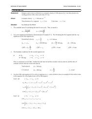
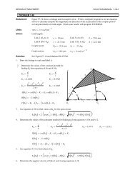
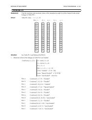
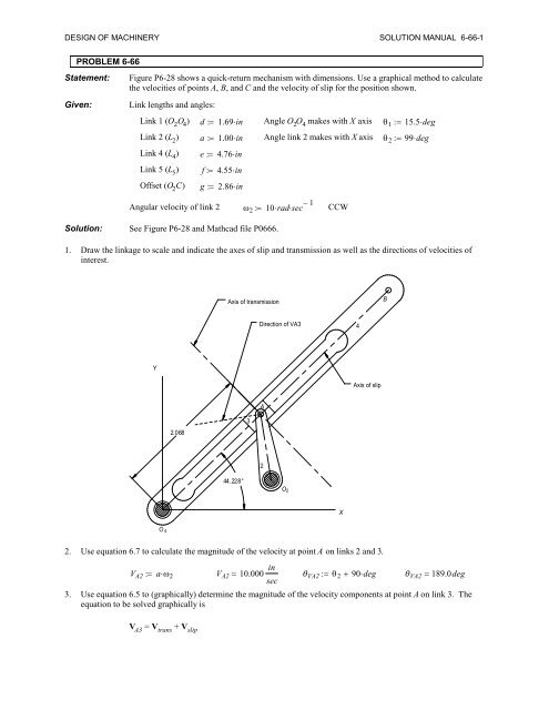
DESIGN OF MACHINERY SOLUTION MANUAL 6-66-1PROBLEM 6-66Statement:Given:Figure P6-28 shows a quick-return mechanism with dimensions. Use a graphical method to calculatethe velocities of points A, B, and C and the velocity of slip for the position shown.Link lengths and angles:Link 1 (O 2 O 4 ) d 1.69inAngle O 2 O 4 makes with X axis 15.5degLink 2 (L 2 ) a 1.00inAngle link 2 makes with X axis 99degLink 4 (L 4 ) e 4.76inLink 5 (L 5 ) f 4.55inOffset (O 2 C) g 2.86inAngular velocity of link 2 10radsec 1CCWSolution: See Figure P6-28 and <strong>Mathcad</strong> file P0666.1. Draw the linkage to scale and indicate the axes of slip and transmission as well as the directions of velocities ofinterest.Axis of transmissionBDirection of VA34YAxis of slipA2.0683244.228°O 4O 2X2. Use equation 6.7 to calculate the magnitude of the velocity at point A on links 2 and 3.V A2 a V A2 10.000 in VA2 90deg VA2 189.0degsec3. Use equation 6.5 to (graphically) determine the magnitude of the velocity components at point A on link 3. Theequation to be solved graphically isV A3 = V trans + V slip
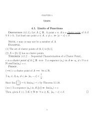
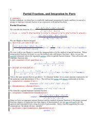
DESIGN OF MACHINERY SOLUTION MANUAL 6-66-2a. Choose a convenient velocity scale and layout the known vector V A3 .b. From the tip of V A3 , draw a construction line with the direction of V slip , magnitude unknown.c. From the tail of V A3 , draw a construction line with the direction of V trans , magnitude unknown.d. Complete the vector triangle by drawing V slip from the tip of V trans to the tip of V A3 and drawing V trans fromthe tail of V A3 to the intersection of the V slip construction line.Y0 5 in/secVA3XV trans1.154V slip1.6344. From the velocity triangle we have:5insec 1Velocity scale factor: k v inV slipV trans 1.634ink v V slip 8.170 insec 1.154ink v V trans 5.770 insec5. The true velocity of point A on link 4 is V trans ,V A4 V transV A4 5.77 insec6. Determine the angular velocity of link 4 using equation 6.7.From the linkage layout above: c 2.068inand 44.228deg V A4 2.790 radcsecCCW7. Determine the magnitude and sense of the vector V B using equation 6.7.V B e V B 13.281 insec VB 90deg VB 134.228 deg8. Draw links 1, 4, 5, and 6 to a convenient scale. Indicate the directions of the velocity vectors of interest. (Seenext page.)
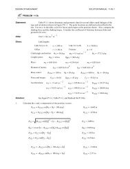
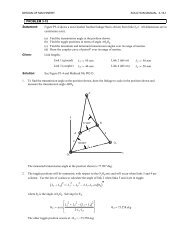
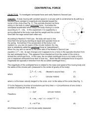
DESIGN OF MACHINERY SOLUTION MANUAL 6-66-3Direction of VCBDirection of VBBC655.805°4Direction of VCYA3244.228°O 2XO49. Use equation 6.5 to (graphically) determine the magnitude of the velocity at point C. The equation to be solvedgraphically isV C = V B + V CBa. Choose a convenient velocity scale and layout the known vector V B .b. From the tip of V B , draw a construction line with the direction of V CB , magnitude unknown.c. From the tail of V B , draw a construction line with the direction of V C , magnitude unknown.d. Complete the vector triangle by drawing V CB from the tip of V B to the intersection of the V C constructionline and drawing V C from the tail of V B to the intersection of the V CB construction line.10. From the velocity triangle we have:5insec 1Velocity scale factor: k v inV C 1.659ink v V C 8.30 insecV B0Y5 in/sec VC 180degVCBVCX1.659