INSTALLATION MANUAL RC-2B RC-3B RC-4B RC-5B RC ... - Maxon
INSTALLATION MANUAL RC-2B RC-3B RC-4B RC-5B RC ... - Maxon
INSTALLATION MANUAL RC-2B RC-3B RC-4B RC-5B RC ... - Maxon

Create successful ePaper yourself
Turn your PDF publications into a flip-book with our unique Google optimized e-Paper software.
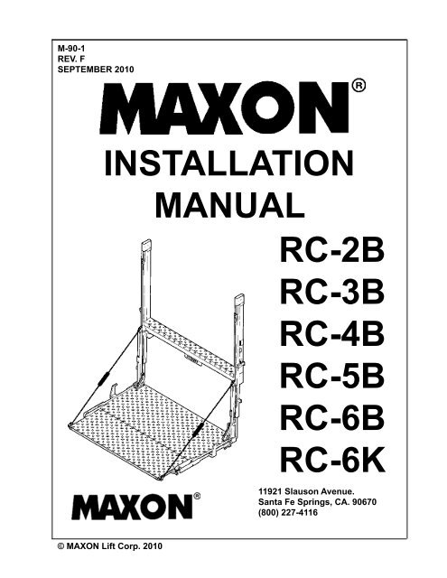
M-90-1REV. FSEPTEMBER 2010<strong>INSTALLATION</strong><strong>MANUAL</strong><strong>RC</strong>-<strong>2B</strong><strong>RC</strong>-<strong>3B</strong><strong>RC</strong>-<strong>4B</strong><strong>RC</strong>-<strong>5B</strong><strong>RC</strong>-6B<strong>RC</strong>-6K11921 Slauson Avenue.Santa Fe Springs, CA. 90670(800) 227-4116© MAXON Lift Corp. 2010
TABLE OF CONTENTSWARNINGS............................................................................................................................ 3SAFETY INSTRUCTIONS..................................................................................................... 3NOTICE.................................................................................................................................. 4INTRODUCTION.................................................................................................................... 5UNIT AS SHIPPED................................................................................................................. 6<strong>INSTALLATION</strong> OF UNIT....................................................................................................... 7WELDING TO FLATBED...................................................................................................... 12HYDRAULIC PIPE <strong>INSTALLATION</strong>..................................................................................... 13POWER PACK <strong>INSTALLATION</strong>........................................................................................... 14FUSED POWER CABLE...................................................................................................... 17PUMP WIRING CAM CLOSER............................................................................................ 18PUMP WIRING HYDRAULIC CLOSER............................................................................... 19ADD HYDRAULIC FLUID..................................................................................................... 20FINAL ADJUSTMENTS........................................................................................................ 22ATTACH DECALS................................................................................................................ 24OPTIONS............................................................................................................................. 26<strong>RC</strong>T LIGHT <strong>INSTALLATION</strong>................................................................................................. 26HAND PUMP OPTION FOR CAM CLOSER........................................................................ 28BATTERY PAK <strong>INSTALLATION</strong> (For Trailers)...................................................................... 29RECOMMENDED LIFTGATE POWER CONFIGURATION................................................. 30BATTERY CABLE MOUNTING, 6 VOLT SYSTEM.............................................................. 3<strong>2B</strong>ATTERY CABLE MOUNTING, 12 VOLT SYSTEM............................................................ 33FIXED RAMP <strong>INSTALLATION</strong>, 6”........................................................................................ 34FIXED RAMP <strong>INSTALLATION</strong>, 12”...................................................................................... 35CART STOP & DUAL CART STOP RAMP <strong>INSTALLATION</strong>................................................. 36HINGED RAMP <strong>INSTALLATION</strong> (STEEL)........................................................................... 37HINGED RAMP <strong>INSTALLATION</strong> (ALUMINUM).................................................................... 38
Comply with the following WARNINGS and SAFETY INSTRUCTIONS while installingLiftgates. See Operation Manual for operating safety requirements.WARNINGS• Do not stand, or allow obstructions, under the platform when lowering the Liftgate. Be sure yourfeet are clear of the Liftgate.• Keep fingers, hands, arms, legs, and feet clear of moving Liftgate parts (and platformedges) when operating the Liftgate.• Correctly stow platform when not in use. Extended platforms could create a hazard forpeople and vehicles passing by.• Make sure vehicle battery power is disconnected while installing Liftgate. Connect vehiclebattery power to the Liftgate only when installation is complete or as required in the installationinstructions.SAFETY SAFETY INSTRUCTIONS INSTRUCTIONS• Comply with all WARNING and instruction decals attached to the Liftgate.• Keep decals clean and legible. If decals are illegible or missing, replace them. Free replacementdecals are available from <strong>Maxon</strong> Customer Service.• Consider the safety and location of bystanders and location of nearby objects when operating theLiftgate. Stand to one side of the platform while operating the Liftgate• Do not allow untrained persons to operate the Liftgate.!WARNING• If it is necessary to stand on the platform while operating the Liftgate, keep your feet and anyobjects clear of the inboard edge of the platform. Your feet or objects on the platform can becometrapped between the platform and the Liftgate extension plate.• Never perform unauthorized modifications on the Liftgate. Modifications may result in early failureof the Liftgate and may create hazards for Liftgate operators and maintainers.• Recommended practices for welding on steel parts are contained in the current AWS (AmericanWelding Society) D1.1 Structural Welding Code - Steel. Damage to Liftgate and/or vehicle, andpersonal injury can result from welds that are done incorrectly.• Read and understand the instructions in this Installation Manual before installing Liftgate.• Before operating the Liftgate, read and understand the operating instructions in OperationManual.• Wear appropriate safety equipment such as protective eyeglasses, faceshield and clothing whileperforming maintenance on the Liftgate and handling the battery. Debris from drilling and contactwith battery acid may injure unprotected eyes and skin.• Be careful working by an automotive type battery. Make sure the work area is well ventilated andthere are no flames or sparks near the battery. Never lay objects on the battery that can short theterminals together. If battery acid gets in your eyes, immediately seek first aid. If acid gets on yourskin, immediately wash it off with soap and water.• If an emergency situation arises (vehicle or Liftgate) while operating the Liftgate, release the controlswitch to stop the Liftgate.• A correctly installed Liftgate operates smoothly and reasonably quiet. The only noticeable noiseduring operation comes from the power unit while the platform is raised and lowered. Listen forscraping, grating and binding noises and correct the problem before continuing to operate Liftgate.11921 Slauson Ave. Santa Fe Springs, CA. 90670 (800) 227-4116 FAX (888) 771-77133
NOTICENOTICE• <strong>Maxon</strong> Lift is responsible for the instructions to correctly install MAXON Liftgates ontrucks or trailers only.• Liftgate installers, not <strong>Maxon</strong> Lift, are responsible for reviewing and complying with allapplicable Federal, State, and Local regulations pertaining to the trailer or truck.11921 Slauson Ave. Santa Fe Springs, CA. 90670 (800) 227-4116 FAX (888) 771-77134
INTRODUCTIONThis publication contains the information required to install the followingmodels and their options; <strong>RC</strong>, <strong>RC</strong>W, <strong>RC</strong>T, <strong>RC</strong>-CL, and <strong>RC</strong>HL from 2000to 6000 pound capacities. If there is any doubt in your mind regarding thesuitability of these lifts being installed on its intended vehicle, or any portionof these instructions that you do not understand, please contact the <strong>Maxon</strong>Customer Service Department for consultation.Unauthorized modification to this equipment may cause prematurefailure or create hazards in its use that are not foreseen at the time of theinstallation. These kinds of changes should be discussed with our EngineeringDepartment before being undertaken.Bed height requirements to ground are 38” laden to 56” unladen.These lifts cannot be installed on bodies with swing type doors.These lifts have been designed to fit bodies that are 96” wide, (102”wide, in the case of the <strong>RC</strong>W Models). If this body has dimensions that aremuch different than these, special brackets will have to be fabricated forattachment. The corner posts of the body must also be made of steel so thatthe lift columns can be welded to it. If they are aluminum, then steel plateswill have to be fabricated to bolt to these corner posts for welding to the liftassembly. Both of the above conditions are rare and therefore have not beenprovided for in this manual. Contact the Customer Service Department if eitherof the above conditions exist.11921 Slauson Ave. Santa Fe Springs, CA. 90670 (800) 227-4116 FAX (888) 771-77135
UNIT AS SHIPPEDDo not remove stands at bottom of column until instructed to do so.Steel box containing pump assembly, also contains a packinglist, instruction manuals, decals, and all necessary hardwareto complete installation.POWER UNIT BOXREINFO<strong>RC</strong>EMENT ANGLE 8”COLUMN SUPPORT ANGLES 48”Two of these 18” angle iron pieces areto be used first to assist in mountingthe lift to the truck, and then to supportthe pump box on trailer installations.The other two are welded to the columnsupport angles.11921 Slauson Ave. Santa Fe Springs, CA. 90670 (800) 227-4116 FAX (888) 771-7713STANDBATTERYPAK OPTIONPUMP BOXSTAND6
<strong>INSTALLATION</strong> OF UNITThere are two pieces of angle iron supports (2-1/2 x 2-1/2 x18”) that have been provided to assist in lining the unit up to thebody. Tack weld them to the top of the lifts main section, juststrong enough to support it on the truck floor till the lift is securedand ready to weld. Put a chalk mark on the center of the unit (onthe thread plate surface) for aligning with the center of the truckbody.Remove support angles after lift is mounted and use them forpump box mount reinforcement.SUPPORT ANGLESUPPORT ANGLE11921 Slauson Ave. Santa Fe Springs, CA. 90670 (800) 227-4116 FAX (888) 771-77137
<strong>INSTALLATION</strong> OF UNIT - ContinuedCorner posts and sill under rear of floor must be clean and free of anyobstructions so that the columns of the rail lift can fit flat against the rear of thebody.Chalk mark a center line at the edge of the rear of the truck floor to line upwith the mark on the liftgate.Using the lifting straps, the unit can now be raised either with a chain hoist orfork lift to a height which will allow the temporary support angles to rest on thebody floor. The unit can be moved to the vehicle or the vehicle to the unit tillthey meet.11921 Slauson Ave. Santa Fe Springs, CA. 90670 (800) 227-4116 FAX (888) 771-77138
<strong>INSTALLATION</strong> OF UNIT - Continued<strong>RC</strong>-2000/3000/<strong>RC</strong>-CR31/4” Fillet Weld. 2” Long<strong>RC</strong>-40001/4” Fillet Weld. 3” Long<strong>RC</strong>-5000/60001/4” Fillet Weld. 4” LongNOTE: See views A & B on next page.Clamp columns to the truck body and weldas shown. Remove forklift or chain hoist.ALL UNITS: 1/8” fillet weldapprox. halfwaydown the column.ALL UNITS: See view C onthe next page.11921 Slauson Ave. Santa Fe Springs, CA. 90670 (800) 227-4116 FAX (888) 771-77139
<strong>INSTALLATION</strong> OF UNIT - ContinuedTyp.A1/4”(Length asspecifiedon previouspage.)OUTSIDE OF COLUMN ASSEMBLYCDO NOT WELD COVE<strong>RC</strong>OVERINSIDE OF COLUMN ASSEMBLYB11921 Slauson Ave. Santa Fe Springs, CA. 90670 (800) 227-4116 FAX (888) 771-7713TYP.1/4” 2WELD TO CORNERPOST AND SILLBOTTOM CORNER OF TRUCK BODY10
<strong>INSTALLATION</strong> OF UNIT - ContinuedCut columns off 20” from ground. Place the 2-1/2” x 18”angle iron provided under at least 2 cross members, toprepare for the following step and weld.Cut one end of each of the 4 foot long angle iron bracesso that it lines up with the lift column and the other endlays flat against the angle iron referred to in the previousparagraph.WELD18”ANGLEWELDCUTSTANDOFF11921 Slauson Ave. Santa Fe Springs, CA. 90670 (800) 227-4116 FAX (888) 771-771320”LIFT COLUMN11
WELDING TO FLATBEDThe column assemblies aretied in to the flat bed side railswith two lengths of channel. Therequired sizes are listed below.NOTE: Mounting Channel is not supplied by <strong>Maxon</strong><strong>RC</strong>-2000/3000/40003”-4.1 #/ft. Channel<strong>RC</strong>-5000/60004”-5.4 #/ft. ChannelCross MemberIf side rail is less than 1/4” thick,weld a 1/4” plate to side rail, thenweld channel to 1/4” plate.<strong>RC</strong>-2000/3000/40003”of 1/4” fillet weld<strong>RC</strong>-5000/60004”of 1/4” fillet weldWeld to side railabove a crossmember.60”Approx.<strong>RC</strong>-2000/3000/40003”of 1/4” fillet weld<strong>RC</strong>-5000/60004”of 1/4” fillet weld11921 Slauson Ave. Santa Fe Springs, CA. 90670 (800) 227-4116 FAX (888) 771-771312
HYDRAULIC PIPE <strong>INSTALLATION</strong>Remove the seven foot long pipe that is strapped to this column of thelift gate (two pipes if lift has hydraulic platform closer), and weld to underside of floor cross members. End of pipe to be about two feet from the end ofthe truck body. Connect the four foot hoses to the end of the pipe(s) closestto the power unit and the other end through the pump box to the pumpassembly. See the last page of “Power Pak Installation” for details.NOTE: Blow air through pipes and hoses before connections are made.Approx. 24”11921 Slauson Ave. Santa Fe Springs, CA. 90670 (800) 227-4116 FAX (888) 771-771313
POWER PACK <strong>INSTALLATION</strong> - ContinuedRun 32 ft. power cable from the pump box, along the chassis frame to thepositive terminal of the battery (assuming the negative is ground). Use frameclips to secure the cable. (Do not attach to the battery terminal until the otherend is fastened on the pump). If the cable is too long, cut to proper length.POWE<strong>RC</strong>ABLESHRINK TUBE1/2”3/8” CABLE ENDTERMINALStrip about 1/2” of the insulation from the end and slide one of thepieces of shrink tube far enough down that it’s out of your way. Solder theterminal end firmly onto the cable.Always wear protective eye covering while you are doing solderingoperations.When it’s cool, slide the shrink tube over the terminal end and heat witha heat gun til it shrinks tightly over the cable and terminal.NOTE:Proper cable connections are extremely important to insure a long andefficient life to all electrical components, therefore, solder type terminals,solder and shrink tubing are provided to insure proper connections. Pleasedo not use the hammer smashing method since the constant bouncing andvibration of the vehicle can eventually cause these types of joints to loosenand deteriorate.This could also be true of crimping if not done properly or the wrong sizetool is used.11921 Slauson Ave. Santa Fe Springs, CA. 90670 (800) 227-4116 FAX (888) 771-7713POWE<strong>RC</strong>ABLEFRAMECLIP15
POWER PACK <strong>INSTALLATION</strong> - ContinuedTRUCKS ONLYRoute the two hoses (3 if hydraulic closer) and the three conductor cord(two cords if hydraulic closer), that come out of the bottom of the lift gate mainframe through the power pak box and connect as shown.TRAILERS ONLY11921 Slauson Ave. Santa Fe Springs, CA. 90670 (800) 227-4116 FAX (888) 771-7713Connect hydraulic hose coming out of bottom of lift gate towelded pipes under body. Tie the cord(s) and the low pressure lineto the pipe and route through power unit box.16
FUSED POWER CABLESHORT END TOVEHICLE BATTERY! WARNINGDo not attach cable to battery until Liftgate iscompletely installed.BATTERY CABLE ASSEMBLY (38’ STD)(INCLUDES REPLACEMENT FUSE KIT)P/N 264422175 AMP REPLACEMENT FUSEKIT P/N 264687OPTIONAL POWER CABLE KITSLONG END TOMOTOR SOLENOID11921 Slauson Ave. Santa Fe Springs, CA. 90670 (800) 227-4116 FAX (888) 771-7713DESCRIPTION PART NUMBER FIGURE40’ CABLE ASSEMBLY(WITH 200 AMP FUSE)264848(CABLE ASSEMBLY)10’ EXTENSION CABLEASSEMBLY264849(EXTENSION CABLE ASSEMBLY)17
FINAL ADJUSTMENTS - ContinuedAdjust Flow Control valve on power pak so that platform opens from avertical position just slow enough so as not to create a banging condition.To ensure that the platform brakes are working properly, perform thefollowing simple test:1. Open Platform and let unit down so that the bottom of the Runner on oneside rests on a floor jack.2. Raise the jack about 3” or so and let the jack down.3. The Runner should stay in the position that it was jacked up to. If it fallsdown to its origional position resting on the jack, then the brake is notworking and must be checked.4. To release engaged brake, raise unit.Perform test on opposite side as well.If platform raises uneven from side to side, adjust per instructions inmaintenance manual. Install lights and add decals.11921 Slauson Ave. Santa Fe Springs, CA. 90670 (800) 227-4116 FAX (888) 771-771323
ATTACH DECALSPAINT DECAL(2 PLACES)P/N 267338-01SERIAL PLATE(REF)DECAL “F” ORDECAL “G”DECAL “C”DECAL “D”DECAL “B”11921 Slauson Ave. Santa Fe Springs, CA. 90670 (800) 227-4116 FAX (888) 771-7713DECAL “E”DECAL “A”DECAL “H”DECAL “I”24
OPTIONSHAND PUMP OPTION FOR CAM CLOSERThe procedure for lifting the platform using the hand pump is as follows:1. Check if the relief valve is closed by using the handle to turn it clockwiseuntil complete stop.2. Close the flow control valve by turning the knob clockwise until it is fullyclosed.3. Locate the handle in the hand pump and operate with an up and downmotion.To lower the platform, open the hand pump relief valve slowly to be able tocontrol the down speed with this valve.NOTE:When going back to normal operation,a. Be sure to have the hand pump closed.b. Open and adjust the flow control valve.HANDLE11921 Slauson Ave. Santa Fe Springs, CA. 90670 (800) 227-4116 FAX (888) 771-7713FLOWCONTROLKNOBRELIEF VALVEHAND PUMP28
BATTERY PAK <strong>INSTALLATION</strong> (For Trailers)Mount the battery pak on either side of the trailer body, as close to thepower source as possible. Using a floor jack or other lifting device, raise thebox so that it’s top touches the underside of the cross members and tack weldto the crossmembers (unless the cross members are aluminum).Place the four plates (included with this kit) against the cross membersand slide down againstthe battery pak. Weldto both structures.(NOTE: Holes areprovided in the mountingplates to allow boltingto aluminum crossmembers).Make surethe box is not in aposition to interferewith the wheelsof the trailer withsliding axle.MOUNTINGPLATESCROSS MEMBERSBATTERY PAKNOTE:These boxescan also beinstalled behindthe wheels ifroom permits.11921 Slauson Ave. Santa Fe Springs, CA. 90670 (800) 227-4116 FAX (888) 771-7713For easier service, mount boxes so that the front of each box is recessedone foot from the side wall of the vehicle body.29
OPTIONSRECOMMENDED LIFTGATE POWER CONFIGURATIONNOTE: Make sure the Liftgate power unit, and all batteries on the vehicle for thepower unit, are connected correctly to a common chassis ground.1. Liftgate, pump box, andadditional battery boxare typically installed ontrailers as shown in FIG.30-1 and on trucks asshown in FIG. 30-2.See the following pagefor battery and cableconnections.LIFTGATEMASTERDISCONNECTSWITCHLIFTGATEPUMP BOXOPTIONALBATTERY BOX,TYPICAL LOCATIONRECOMMENDED LIFTGATE & BATTERY BOX<strong>INSTALLATION</strong> ON TRAILERFIG. 30-1MASTERDISCONNECTSWITCHTRACTOR BATTERIES,TYPICAL LOCATIONCHARGE LINEPOWE<strong>RC</strong>ABLETRUCK BATTERYCI<strong>RC</strong>UIT BREAKER,REQUIRED LOCATIONPOWE<strong>RC</strong>ABLECI<strong>RC</strong>UITBREAKERTRACTOR BATTERYCI<strong>RC</strong>UIT BREAKER,REQUIRED LOCATIONTRAILER-MOUNTEDCI<strong>RC</strong>UIT BREAKER,ADDITIONAL RECOM-MENDED LOCATION11921 Slauson Ave. Santa Fe Springs, CA. 90670 (800) 227-4116 FAX (888) 771-7713LIFTGATELIFTGATEPUMP BOXCI<strong>RC</strong>UITBREAKEROPTIONALBATTERY BOX,CHARGE LINETYPICAL LOCATIONTRUCK BATTERIES,TYPICAL LOCATIONRECOMMENDED LIFTGATE & BATTERY BOX<strong>INSTALLATION</strong> ON TRUCKFIG. 30-230
RECOMMENDED LIFTGATE POWER CONFIGURATION - ContinuedNOTE: Always connect fused end of power cable to battery positive (+) terminal.2. Recommended battery boxsetup for 6 volt batteries isshown in FIG. 31-1.175 AMP FUSED POWER CABLE(SEE NOTE)POWER CABLETO PUMP BOXGROUND CABLETO PUMP BOX3. Recommended battery boxsetup for 12 volt batteries isshown in FIG. 31-2.175 AMP FUSED POWER CABLE(SEE NOTE)POWER CABLETO PUMP BOX(+)BATTERYCABLES(+)BATTERYCABLES150 AMP CI<strong>RC</strong>UITBREAKER6 VOLT BATTERY CONNECTIONSFIG. 31-1150 AMP CI<strong>RC</strong>UITBREAKER150 AMP CI<strong>RC</strong>UIT BREAKER(NEAR TRUCK ORTRACTOR BATTERY AND/ORNOSE OF TRAILER)CHARGE LINE TOTRUCK OR TRACTORBATTERY(-) BATTERYCABLENOTE: Always connect fused end of power cable to battery positive (+) terminal.150 AMP CI<strong>RC</strong>UIT BREAKER(NEAR TRUCK ORTRACTOR BATTERY AND/ORNOSE OF TRAILER)CHARGE LINE TOTRUCK OR TRACTORBATTERY11921 Slauson Ave. Santa Fe Springs, CA. 90670 (800) 227-4116 FAX (888) 771-7713GROUND CABLETO PUMP BOX(-) BATTERYCABLES12 VOLT BATTERY CONNECTIONSFIG. 31-231
BATTERY CABLE MOUNTING, 12 VOLT SYSTEMFROM CONNECTORPLUGGROUND CABLE+ - + -12 VOLTBATTERY12 VOLTBATTERYCI<strong>RC</strong>UIT BREAKER11921 Slauson Ave. Santa Fe Springs, CA. 90670 (800) 227-4116 FAX (888) 771-7713MOTOR SOLENOIDCABLEMOTOR SOLENOID33
OPTIONSFIXED RAMP <strong>INSTALLATION</strong>, 6”Lower the platform to level ground. Line up top edge of ramp with thefront edge of the platform.Weld 1/8” beads two inches long about every 6 or 8 inches along theentire length of the platform. Repeat procedure for the underside of theplatform.WELD11921 Slauson Ave. Santa Fe Springs, CA. 90670 (800) 227-4116 FAX (888) 771-7713WELD34
FIXED RAMP <strong>INSTALLATION</strong>, 12”Lower the platform to level ground. Line up top edge of ramp with thefront edge of the platform.WELDACut rear edges of ramp as shown:Single piece platform “A” = 3/8”Folding platforms “A” = 1/2”11921 Slauson Ave. Santa Fe Springs, CA. 90670 (800) 227-4116 FAX (888) 771-7713WELDWeld 1/8” beads two inches long about every 6 or 8 inches along theentire length of the platform. Repeat procedure for the underside of theplatform. Weld gussets full length.35
CART STOP & DUAL CART STOP RAMP <strong>INSTALLATION</strong>1. With the platform on the ground, center the Cart Stop Ramp against thebutt end of the platform. Rest the Ramp Blocks on top of the platform and letthe Ramp Tip touch the ground. Weld both sides into place.Cart Stop RampRamp BlocksCart Stop Ramp Tip to be flushwith bottom surface of Platform.Platform1/4” Weld2. Pop open the Cart Stop Section of the ramp for ease of welding. Weld thetop & bottom of the Ramp to the Platform with 2” long welds on approximately12” centers. Grind all welds smooth and touch up with paint.Cart Stop RampNOTE: REPEAT THESTITCH WELD ON THEBOTTOM OF RAMP11921 Slauson Ave. Santa Fe Springs, CA. 90670 (800) 227-4116 FAX (888) 771-77131/4” 2”-12”Platform36
7/8”1/8”7/8”1/86,7446,788HINGED RAMP <strong>INSTALLATION</strong> (STEEL)HINGED RAMP <strong>INSTALLATION</strong> (STEEL)Typ.1/8”Typ. Typ.1/8” 1/8Typ.1/81/16”(Typ.)111/16”(Typ.)1122551/8”1/8Typ.Typ.C L6”1/8”12”6”43-1/4” 46”(Typ. 90” Ramp) 12” (Typ. 90” Ramp)38-1/4” 43-1/4” 46” 41”(Typ. 90” 80” Ramp)(Typ. 90” 80” Ramp)38-1/4”(Typ. 80” Ramp)8 88 81-7/8”7” (12” & 20” ramps)3” (6” ramp only)1/2”(Typ.) 7” (for 12” & 20” ramps)3” (for 6” ramp only)12” & 20” RAMPS 6” RAMPSC L341/841”(Typ. 80” Ramp)Item Qty. Part No. Description225989-1 12"x 90" RAMP & HINGE ASSY.225989-2 6"x 90" RAMP & HINGE ASSY.225989-3 12"x 80" RAMP & HINGE ASSY.1 1225989-4 6"x 80" RAMP & HINGE ASSY.225989-5 20"x 90" RAMP & HINGE ASSY.225989-6 20"x 80" RAMP & HINGE ASSY.2 4 092143-01 TUBE 1.5 OD x1.015 ID x1.75LG.21/2”(Typ.)1/8”111-7/8”12” & 20” RAMPS221739-1 LATCH PLT. WMT. 1PC PTFM.6” RAMPS3 1221739-2 LATCH PLT. WMT. 2PC PTFM.4 2 225998 BAR RD. 3/4" DIA. x 8" LG.5 2 201020 FLAT, 3/8 x 1 x 1-1/2" LG3421/8441/2”1/2”11921 Slauson Ave. Santa Fe Springs, CA. 90670 (800) 227-4116 FAX (888) 771-771311921 Slauson Ave. Santa Fe Springs, CA. 90670 (800) 227-4116 FAX (888) 771-77136 2 202698-41 CHAIN 18" LG. (12" & 20" RAMP ONLY)7 2 202698-43 CHAIN 11" LG. (6" RAMP ONLY)8 2 224342 LUBE FITTING37 PAGE 33
HINGED RAMP <strong>INSTALLATION</strong> (ALUMINUM)HINGED RAMP <strong>INSTALLATION</strong> (ALUMINUM)11921 Slauson Ave. Santa Fe Springs, CA. 90670 (800) 227-4116 FAX (888) 771-7713661/2”1/2”1/8” 1-101/8 1-1044Typ.1/8”55Typ.1/8Typ.1/8”Typ.1/81/16”(Typ.)1/16”(Typ.)5/8”5/8”1111225/8”5/8”1/81/8Locate Swivel this way on36”, 42”, 48” pltfm. only.Locate Swivel this way on36”, 42”, 48” pltfm. only.Typ.Typ.44331/8”1/810”10”6-7/8”(Typ. 80” Pltfm.)3-13/32” 6-7/8”(Typ. 80” 70” Pltfm.)3-13/32”(Typ. 70” Pltfm.)1-1/2”(Typ.)Item Qty. Part No. Description1 1221543 16"x 80" RAMP ASSY.Locate Swivel thiswayLocateon 60”,Swivel72”,this76”,way84”onpltfm.60”, 72”,only.76”,84” pltfm. only.5/8”5/8”1-1/2”(Typ.) 11-1/2” (36”,42”,48”Pfm)9-1/2” (60”,72”,76”,80”Pfm)11-1/2” (36”,42”,48”Pfm)9-1/2” (60”,72”,76”,80”Pfm)221543-1 16"x 80" REINFO<strong>RC</strong>ED ALUM. RAMP ASSY.229569 20"x 80" ALUM. RAMP ASSY.229569-01 20"x 80" REINFO<strong>RC</strong>ED ALUM. RAMP ASSY.221543-100 16"x 70" RAMP ASSY.2 1 092143-01 TUBE 1.5 OD x1.015 ID x1.75LG.221739-1 LATCH PLT. WMT. 1PC PTFM.3 1221739-2 LATCH PLT. WMT. 2PC PTFM.4 1 225985 PIPE 3/4" SCH. 80 x 60" LG.5 2 201020 FLAT, 3/8 x 1 x 1-1/2" LG11921 Slauson Ave. Santa Fe Springs, CA. 90670 (800) 227-4116 FAX (888) 771-77136 2 202698-41 CHAIN 18" LG.38PAGE 34