Balun Bulletin- CCTV Systems- Termination - West Penn Wire
Balun Bulletin- CCTV Systems- Termination - West Penn Wire
Balun Bulletin- CCTV Systems- Termination - West Penn Wire

Create successful ePaper yourself
Turn your PDF publications into a flip-book with our unique Google optimized e-Paper software.
Cables and Connectors: V/Cat UTP BalancedTwisted Paired Cables- V/CatKnown as Balanced cableV/Cat: 2 Pair Balanced UTP Cat 5E type 100Ohm + 2 Conductors for power.CC2418 and CC252418 (Plenum)CC2416 and CC252416 (Plenum)PAIR 1: VIDEOPAIR 2: VIDEO or DATA/CONTROL2 CONDUCTORS (18 or 16AWG)- POWERV/Cat cables are designed with two Category 5E type pairs. Pair one is used to carry <strong>CCTV</strong> video, and pairtwo can also carry video, or data/control signals. The cable includes two conductors for power to the camera(18 or 16AWG).The V/Cat cable is constructed in a siamese or shotgun manner. This design allows the cable to be split intotwo parts for ease of connections in an patch panel/ equipment rack.Connectors: See Page 4.3
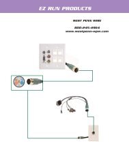
Cables and Connectors: UTP- BalancedStriping Instructions: 32-EZP - Plug1. Strip off 2.00” of jacket2. Straighten and align wires to T568B or T568A - Trim Pairs3. Insert wires into connector body4. Pull tight to ensure jacket is .250” inside connector body5. Verify wire location and orientation6. Insert 32-EZP connector into crimp tool- TL-EZRJ457. Verify connector is completely seated and cable is fully inserted8. Squeeze handle of TL-EZRJ459. Remove excess wires10. Check jacket strain relief11. Check that contacts are all engaged12. Check that contact dividers are not damaged13. Check to see if both ends of the cable have been terminatedTool less <strong>Balun</strong> Installation:CN-TL, CN-MTL, CN-RJ45PT1. Run Category 5E between camera and therest of your <strong>CCTV</strong> equipment. Each pair willcarry a video signal.2. Strip the Cat 5E cable 1/4”-1/2”.3. Connect the pair of wires to the balunaccording to the diagram.Connect with the correct polarity to thebalun on both ends.(Insert wires vertically into slots)(Bend wires down into IDC strip and close theIDC cap and external cover).4. Connect the balun to thecamera.4
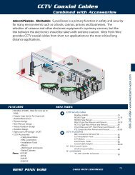
Cables and Connectors: Coaxial Cables- UnbalancedCoaxial Cables-Known as Unbalanced cableCoaxial Cables- are Unbalanced 75 ohm.MiniMax- 825 and 25825 (Plenum)RG59/U- 815 and 25815 (Plenum)RG6/U - 806 and 25806 (Plenum)Connectors: 75 Ohm BNC MaleBNC 75 Ohm Connectors are needed in a UTP <strong>CCTV</strong> system.BNC Connectors can be connected to the coaxial cable by Crimp style or Compression style.Cables: Crimp Connector: Compression Connector:MiniMax Cables CN-BM74-18 CN-BNCP-825RG59/U Non-Plenum CN-BM73-2 CN-BNCP-59RG59/U Plenum CN-BM73-30 CN-FS59BNCPL4RG6/U Non-Plenum CN-BM73-5 CN-BNCP-6RG6/U Plenum CN-BM73-4 CN-FS6BNCPL2Cable Assemblies: 75 ohm BNC to 75 ohm BNCCable Assemblies may be needed between the camera and the balun or within the equipment rack.Varying length and color maybe needed to complete the installation.Cable Assemblies:MinimaxCN-7B825**-xx- Replace ** - with Color: (BK, BL, RD, GN, WH, YE)Replace xx- with Length: (3, 6, 10,15,20,25) ft.Custom lengths are available from <strong>West</strong> <strong>Penn</strong> <strong>Wire</strong>5
Connector Installation Crimp Style BNCCrimp <strong>Termination</strong>- <strong>CCTV</strong> RG59/U - 815 and 25815Stripping of RG59/U for Crimp Connectors:1. Feed crimp sleeve ferrule onto cable jacket.2. Strip cable - using TL-121.3. Flair braid back over the jacket• Foil can stay bonded to the dielectricor peel the foil off the cable.4. Feed center pin crimp sleeve over the centerconductor, until it butts against the dielectricCrimp using .068” crimp die on TL-104or TL-803.Note: if the crimp sleeve is not fittingsnug against the dielectricyou will need to trim the centerconductor.5. Feed connector body on to the cable.• Connector body will “Snap” into placewhen seated properly.6. Flair exposed braid evenly over the connectorbody.7. Feed crimp ferrule over the connector body• Crimp using- .255 crimp die on TL-105or TL-803.815- CN-BM73-225815- CN-BM73-306
Connector Installation Compression Style BNCCompression <strong>Termination</strong>- <strong>CCTV</strong> RG59/U Plenum 25815Stripping of 25815 for Compression Connectors1. Strip cable - using TL-CCSTTL-CSST• Place cable in tool rotate clockwisefor 3 turns, counter-clockwise for 3turns.• Release tool from the cable• extract stripped material from thecable2. Feed center conductor into the internalcenter pin of the connectorPush the connector onto the cable• Push until center pin is seatedproperly in the connector body.3. Compress connector using a TL-SNSA• For the CN-FS59BNCPL4set the tool at 9Compression <strong>Termination</strong>- <strong>CCTV</strong> RG59/U 815Stripping of 815 for Compression Connectors:1. Strip Cable - using TL-CSSTTL-CSST• Place cable into tool• Turn tool clockwise 2-3 turns• Turn tool counter-clockwise 2-3 turns• Release the cable from the tool• Peel stripped material from the cable2. Push the connector onto the cable• Window will help visually guide thecable into place.NOTE: CN-BNCP-59 Internal cableguide is a necked downcylinder to ensure proper seating of thecenter conductor3. Compress connector using a TL-SNSA• For the Window CompressionConnectors, set TL-SNSA toolat 2.7