PR9648-V1_6-00- Prospekt - Martens Elektronik GmbH
PR9648-V1_6-00- Prospekt - Martens Elektronik GmbH
PR9648-V1_6-00- Prospekt - Martens Elektronik GmbH

You also want an ePaper? Increase the reach of your titles
YUMPU automatically turns print PDFs into web optimized ePapers that Google loves.
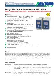
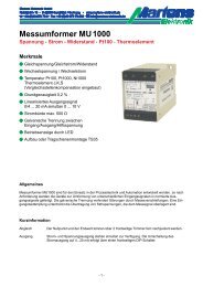
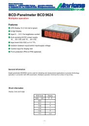
<strong>Martens</strong> <strong>Elektronik</strong> <strong>GmbH</strong>Kiebitzhörn 18 • D-22885 Barsbüttel/Germany • www.martens-elektronik.deF+49-(0)40-670 73-0 • Fax +49-(0)40-670 73-288 • J info@martens-elektronik.deProductivity-Meter PR 9648Speed - flow - synchronism - slip - passing time - revolution per time<strong>Elektronik</strong>FeaturesM LED-display, 14.2 mm redM Display range ±99999 digitM 0 ... 3 decimal points programmableM 2 digital inputs for summation,difference, ratio and product measurementM Hold-inputM Integrated transmitter-supply 24/8 V DCM Max. 4 outputs, SPDT relay or transistorM Display conversion programmableM Isolated analog output,0/4 ... 20 mA and 0/2 ... 10 V DCM Front protection IP65GeneralThe Productivity-Meter <strong>PR9648</strong> analyses impulse rates, representing a speed, flow, passing time or revolutionsper time. The displayed values therefore always refer to a determined time unit and represent productivity.There are extensive functions programmable (see page 6). Since impulses and unit of a displayed value cantake any relation, the device offers extensive conversion possibilities.Short informationProgramming Parameters are programmed via front-side membrane keypadTransmitter-supply The integrated transmitter supply allows direct connection of pnp initiators, light barriers,mechanical switch contacts, proximity switches, rotary encoder (24 V DC) and Namur initiators(8 V DC).Input prescaler An input prescaler has separate programming function for input A and B.Display conversion A separate programmable divisor and factor makes the display adaptable as required.Alarm outputs Switching performance min. or max., hysteresis, on-delay time and off-delay time are programmablein range from 1 s up to 9 h.Analog output Proportional to the display value an isolated analog output signal 0 ... 20 mA/0 ... 10 V DCor 4 ... 20 mA/2 ... 10 V DC can be generated. Start value and end value are prorammable.Output changes automatically from current signal to voltage signal, depending on burden.Hold function Display freezes by control input level 24 V DC or voltage free contact (see page 3).- 1 -
Technical dataPower supplySupply voltage : 230 V AC ±10 %; 115 V AC ±10 %, 24 V AC ±10 % or 24 V DC ±15 %Power consumption : max. 3.5 VAOperating temperature : -10 ... +55 °C; 14 ... 131 °FRated voltage: 250 V~ acc. to VDE 0110 between input/output/supply voltageover-voltage categoric IIITest voltage: 4 kV=, between input/output/supply voltage-conformity : EN55022, EN60555, IEC61<strong>00</strong>0-4-3/4/5/11/13InputPNP input : Ri = 6.3 kΩ level: < 4 V low; > 8.5 V high;Hysteresis > 2.5 V, max. 35 V DCNamur input : Ri appr. 1 kΩ (2.2 mA high;Hysteresis > 0.5 mA max. 35 V DCImpulse frequency : Input A or B = 0.1 Hz ... 15 kHz, A and B together = 0.1 Hz ... 8 kHz,switch contact = 0.1 Hz ... 30 Hz, 2-channel rotary encoder = 0.1 Hz ... 10 kHz;Min. Impulse width : Electronic impulse 50 μs, switch contact 5 msTime base: Seconds, minutes or hoursAccuracy: ≤ 0.<strong>00</strong>3 % ±1 DigitHold input: 24 V DC or switching contactTransmitter supply : 8 V DC (Namur), 24 V DC (PNP), Ri appr. 150 Ω,max. 50 mA (max. 25 mA with 4 relay outputs)Display: LED red, 14.2 mmDisplay range: -99999...999999 Digit, leading zero suppressionParameter display : LED 2-digit red, 7 mm (parameter - and output indicator)OutputRelay: SPDT < 250 V AC < 250 VA < 2 A, < 3<strong>00</strong> V DC < 50 W < 2 ATransistor: max. 35 V AC/DC, max. 1<strong>00</strong> mA, short circuit protectedAnalog output: 0/4 ... 20 mA burden ≤ 5<strong>00</strong> Ω; 0/2 ... 10 V burden >5<strong>00</strong> Ω, isolatedAutomatic output changing (burden dependent)-Accuracy: 0.1 %; TK 0.01 %/KPanel case: DIN 96x48 mm, material PA6-GF; UL94V-0Dimensions: Front 96x48 mm, mounting depth 1<strong>00</strong> mm,Weight: max. 390 gElectrical connection : Clamp terminals, 2 mm² single wire, 1,5 mm² flexible wire, AWG14Protection: Front IP65, terminals IP20, fingersafe acc. to German BGV A3DimensionsSealTerminal strip positionPanel cut-out acc. toDIN 437<strong>00</strong>-96x48- 2 -
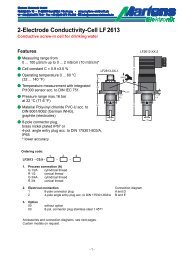
Connection diagramsTerminal strip A2-channelrotary encoder(ext. supply)PNP-Initiator,rotary encoder(24 V DC)Namur-Initiator(8 V DC)SwitchingcontactInput AInput BGnd24 V DCHoldTerminal strip B (varies with version)2 alarm outputsRelay Transistor24 V/8 Vmax. 50 mATransmittersupplyTerminal strip C (varies with version)2 alarm outputs Analog outputRelay Transistor AOTerminal strip D supply voltage (varies with version)- 3 -
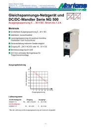
Controls and indicatorsField foradditional textActual valueParameter displayor activatedalarm outputs. For se-Field for unitParameter buttonDown buttonUp buttonDescriptionOperating of the device is arranged in 2 levels. The requested parameter can be called by buttonlections within a parameter or for entering data, use buttons and .Button combinations:+ one parameter back+ setting parameter to zero or minimum valueAfter power-on the device is located in the Working level. Set points of the alarm outputs can be programmedif they are available.Pressing the button for more than 2 seconds, activates the Configuration level. Now all the parameterswhich define the function of the device can be programmed. E.g. the switching performance of the alarm outputs,measuring input and the analog output.After finishing the configuration or when no button was pushed for more than 2 minutes, the program returns tothe Working level. Leaving the Configuration level is possible at any time by pressing the button for morethan 2 seconds.Parameter display as status indicator for the alarm outputs A1-A4.Segments f (A1 / A3) and/or b (A2 / A4) are flashing with 2 Hz, when delay time is active.Segments e (A1 / A3) or c (A2 / A4) are output indicators.Error messages: Reading this symbol in the parameter display a parameter failure has been occurred. The displayflashes. When pushing one of the buttons the error code will be deleted and the device is runningwith the factory programmed parameters. Configuration and function of the device must be checked.If error occurs again, please ship the device to factory for repair service. Programming lock active. See configuration page 9. OverflowStart-up note: The device has to be configured, before it can be used ⇒ see page 6- 4 -
Notes to representationParameter is only displayed when configuratedParameter is only displayed when feature is included (see order code)Please Note: All parameters can be called if they are not blocked by other programmed parameters and ifthey are available. Factory settings are shown in the display.Working levelButton Display DescriptionActual valueOutput indication(only if installed and activated).Max. peak reading.Reset with buttons or , and at every power off.Min. peak reading.Reset with buttons or , and at every power off....Setpoint output A1.Setting possible from ... Digitwith buttons and .Setpoint output A4.Setting possible from ... Digitwith buttons and .- 5 -
ConfigurationButton Display Description (Display graphic shows factory settings)Press2 s1Function: Input configuration : A up, B down : A up, B up : rotary encoder : ratio or passing time (⇒ see page 10) : percentage of deviation (A-B)/B x 1<strong>00</strong> : percentage of deviation (B-A)/B x 1<strong>00</strong>Selection with buttons and .2Input frequency : ≤ 30 Hz, for switching contacts : ≤ 15 kHz, for electronic outputsSelection with buttons and .3Prescaler input ASetting possible from ... digit with buttons and .(only every n th impulse is counted)4Prescaler input BSetting possible from ... digit with buttons and .(only every n th impulse is counted)5Constant input BSetting possible from ... ... digit with buttons and .( = no function)Input B is deactivated. Input signal will be replaced by Constant . This constantenables to measure e.g. the slippage of a motor, the deviation from a referencevalue or the passing time in a continuos heater.6Transmitter supply/input level : 24V DC for pnp-initiatoren : 8V DC for Namur-initiatoren*(* with ext. 5V supply also suitable for TTL-signals) : only for factory settingsSelection with buttons and .continuepage 7- 6 -
Button Display Description (Display graphic shows factory settings)78Time base : hours (h -1 ) : minutes (min -1 ) : seconds (s -1 )Selection with buttons and .Refresh time ( displayed time)Setting possible from ... secondswith buttons and .Maximum display accuracy with will be reached : ≥( max. display time in digit) x 0.<strong>00</strong><strong>00</strong>24 sExample: max. display value 12<strong>00</strong>.0 =12<strong>00</strong>0 x 0.<strong>00</strong><strong>00</strong>24 = 0.288s ⇒ ≥ 0.3 sNote:At minimum 2 impulses must run the input within one refresh cycle (refresh time)910Decimal point position (floating point). . . .Selection with buttons and .Digital filter Selection with buttons and .11Divisor for displaySetting possible from ... Digitwith buttons and .12Factor for displaySetting possible from ... Digitwith buttons and .13Sign : no sign for measuring value and parameter : with sign; the output activation referring belongs to the sign(depending on direction of movement)Selection with buttons and .continuepage 8- 7 -
Button14Display Description (Display graphic shows factory settings)Switching performance output A1 : no action (min): continous contact: on-off (max) : continous contact: off-onSelection with buttons and .15Setpoint output A1Setting possible from ... digit with buttons and .Decimal points only displayed if a fixed decimal point was programmed16Hysteresis of alarm output A1Setting possible from ... digitwith buttons and . mode without decimals.17Switch-on delay time alarm output A1.Setting possible from ... (h.mm.ss)with buttons and .18Switch-off delay time alarm output A1.Setting possible from ... (h.mm.ss)with buttons and .Note:The parameter settings for A2 ... A4 have to be configured the same way.continuepage 9- 8 -
Button Display Description (Display graphic shows factory settings)19Analog output mA (0 - 10 V DC) mA (2 - 10 V DC)The switch-over from current to voltage output is load dependent(≤ 5<strong>00</strong> Ω = current output, > 5<strong>00</strong> Ω = voltage output).Selection with buttons and .20Start value for analog outputSetting possible from ... Digitwith buttons and .Decimal point only shown if programmed.21End value for analog outputSetting possible from ... digit with buttons and .With fixed decimal point programming the difference between start- and end valuemust be at minimum 4<strong>00</strong>0 digit to get the maximum display resolution. Withfloating point ( ), parameter und changing automatically for best resolution.If the start value > end value , the output works with decreasing characteristic.Decimal points only shown if a fixed decimal point was programmed22Programming lock : no lock : configuration level locked : all parameters locked : only with analog output (for factory settings)Selection with buttons and .Return to the working levelcontinuepage 9- 9 -
Measurement of passing timeNormally display value will increase with input impulse sequence. But when measuring passing time, it will bejust reversed. The more pulses per time will run the input the less will be the passing time.For measuring passing time following parameters are important:1. Function: Input configuration ⇒ (must be selected)2. Constant Input B ⇒ Total number of impulses for one passing cycle. If this value >99999 Digit, input must beadapted by prescaler input A.Impulse for 1 passing cycle = ≤ 99999 digit 3. Prescaler input A ⇒ enter smallest possible value to get the maximum display range4. Time base ⇒ select time baseNote:If < 1<strong>00</strong><strong>00</strong> digit, it will be necessary for accuracy measurement to change followingparameters:a. change time base up (e.g. from s in min)b. multiply with factor 60If the result >99999, parameter d A must be adapted (see point 2.)5. Refresh time ⇒ Within the refresh interval at least 2 input impulses must run the input.- 10 -
ExampleCalculating the passing time of a continue drying oven in minutes, with one decimal point.Following data are known:Length of oven30mDistance per one resolution of the measuring shaft 0.1mNumber of impulses per one resolution of the measuring shaft 5<strong>00</strong>Time baseminDecimal point position 0.0Sensor typepnp-initiatorThe maximum impulses for one passing cycle at input A5<strong>00</strong> impulses0.1mx 30m = 15<strong>00</strong><strong>00</strong> impulsesThe maximum value for (with selected decimal point 0.0) could be entered is 9999.915<strong>00</strong><strong>00</strong> = ≤ 99999 Digitd AIf the parameter is selected with value 20, the result as shown:15<strong>00</strong><strong>00</strong> = = 75<strong>00</strong>.0 = (75<strong>00</strong>0 Digit)20Configuration for this measuring task: : : : : : : : : . : : f : : - 11 -
<strong>Martens</strong> <strong>Elektronik</strong> <strong>GmbH</strong>Kiebitzhörn 18 • D-22885 Barsbüttel/Germany • www.martens-elektronik.deF+49-(0)40-670 73-0 • Fax +49-(0)40-670 73-288 • J info@martens-elektronik.de<strong>Elektronik</strong>Ordering code<strong>PR9648</strong> -1.-2.-3.-4.-5.-6.-7.1. Terminal strip A1 2 configurable impulse inputs,integrated transmitter supply,display conversion programmable,hold input2. Terminal strip B<strong>00</strong> not installed2R 2 alarm outputs2T 2 alarm outputs3. Terminal strip C<strong>00</strong> not installed2R 2 alarm outputs2T 2 alarm outputsAO Analog outputrelaytransistorrelaytransistor0/4 ... 20 mA or 0/2 ... 10 V DCisolated4. Terminal strip D supply voltage0 230 V AC ± 10 % 50-60 Hz1 115 V AC ± 10 % 50-60 Hz4 24 V AC ± 10 % 50-60 Hz5 24 V DC ± 15 %5. Option<strong>00</strong>01without optionmin- and max-peak-hold6. Unit (on the panel front)7. Additional text (on the additional text field on the panelmeter,maximum 3 x 90mm WxH )10/04-<strong>V1</strong>.6-<strong>00</strong>- 12 -