- Page 1:
SMYOOO2.,MOS MemoryData Book1984II
- Page 9 and 10:
ALPHANUMERIC INDEX TO DATA SHEETSSM
- Page 11 and 12:
TABLE OF CONTENTSALPHANUMERIC INDEX
- Page 13 and 14:
MOSLSIRAMs, ROMs, EPROMsSELECTION G
- Page 15 and 16:
If you want to give it a try for yo
- Page 17 and 18:
INTERCHANGEABILITY GUIDEPART 1 -ALT
- Page 19 and 20:
INTERCHANGEABILITY GUIDEFUJITSUMB 8
- Page 21 and 22:
INTERCHANGEABILITY GUIDEMOTOROLAMCM
- Page 23 and 24:
INTERCHANGEABILITY GUIDETOSHIBATMM
- Page 25 and 26:
INTERCHANGEABILITY GUIDESTATIC RAMS
- Page 27 and 28:
Alphanumeric Index, Table of Conten
- Page 29 and 30:
GLOSSARY fTIMING CONVENTIONS/DATA S
- Page 31 and 32:
GLOSSARY/TIMING CONVENTIONS/DATA SH
- Page 33 and 34:
GLOSSARY!TIMING CONVENTIONS/DATA SH
- Page 35 and 36:
GLOSSARY/TIMING CONVENTIONS/DATA SH
- Page 37 and 38:
GLOSSARY/TIMING CONVENTIONS/DATA SH
- Page 39 and 40:
Alphanumeric Index, Table of Conten
- Page 41 and 42:
MOSLSITMS411616,384-811 DYNAMIC RAN
- Page 43 and 44:
TMS411616,384·811 DYNAMIC RANDOM·
- Page 45 and 46:
1MS411616,384-811 DYNAMIC RANDOM-AC
- Page 47 and 48:
TMS411616.384·81T DYNAMIC RANDOM·
- Page 49 and 50:
TMS411616,384·811 DYNAMIC RANDOM·
- Page 51 and 52:
zIiADDRESSES~!.....RASCASwDO"*. i,*
- Page 53 and 54:
TMS411616,384-81T DYNAMIC RANDOM-AC
- Page 55 and 56:
MOSLSITMS416165,536-81T MULTIPORT M
- Page 57 and 58:
TMS416165,536-811 MULTIPORT MEMORYf
- Page 59 and 60:
TMS416165,536-BIT MULTIPORT MEMORYs
- Page 61 and 62:
TMS416165,536-0IT MULTIPORT MEMORYc
- Page 63 and 64:
TMS416165,536·BIT MUL TIPORT MEMOR
- Page 65 and 66:
TMS416165,536 o BIT MUL TIPORT MEMO
- Page 67 and 68:
TMS416165,536·811 MULTIPORT MEMORY
- Page 69 and 70:
zI[~~~co,.. twiRL) _,RAS:::~ SI l L
- Page 71 and 72:
TMS416165,536·BIT MULTIPORT MEMORY
- Page 73 and 74:
~ ___TMS416165.536-BIT MUL TIPORT M
- Page 75 and 76:
0>~a~~i'i_';:;Z~~~d~c:::• s:~lTl~
- Page 77 and 78:
TMS416165,536-8IT MULTIPORT MEMORY1
- Page 79 and 80:
MOSLSITMS4164, SMJ416465,536-8IT DY
- Page 81 and 82:
TMS4164, SMJ416465,536-811. DYNAMIC
- Page 83 and 84:
TMS416465,536-811 DYNAMIC RANDOM-AC
- Page 85 and 86:
TMS416465,536·811 DYNAMIC RANDOM·
- Page 87 and 88:
TMS416465,536-811 DYNAMIC RANDOM-AC
- Page 89 and 90:
SMJ416465,536-011 DYNAMIC RANDOM-AC
- Page 91 and 92:
SMJ416465,536-81T DYNAMIC RANDOM-AC
- Page 93 and 94:
SMJ416465,536-011 DYNAMIC RANDOM-AC
- Page 95 and 96:
TMS4164, SMJ416465,536·81T DYNAMIC
- Page 97 and 98:
TMS4164, SMJ416465,536·8IT DYNAMIC
- Page 99 and 100:
z~~gz~.J:>.c1J
- Page 101 and 102:
Z~d~~~~0,'...."CIIICCCD:3of. twIRL)
- Page 103 and 104:
MOSLSITMS4256. TMS4257262.144·8IT
- Page 105 and 106:
TMS4256, TMS4257262,144·8IT DYNAMI
- Page 107 and 108:
TMS4256, TMS4257262,144-8IT DYNAMIC
- Page 109 and 110:
TMS4256, TMS4257262,144·8IT DYNAMI
- Page 111 and 112:
TMS4257262.144·8IT DYNAMIC RANDOM
- Page 113 and 114:
TMS4256, TMS4257262,144·BIT DYNAMI
- Page 115 and 116:
TMS4256, TMS4257262,144·8IT DYNAMI
- Page 117 and 118:
TMS4257262,144·81T DYNAMIC RANDOM
- Page 119 and 120:
Z~d~~~~.!..JcoNOTE:'CIIICO(1),- twI
- Page 121 and 122:
i:Z~d~~z~+:>0Co ......"CCICCCD:3og.
- Page 123 and 124:
TMS4256, TMS4257262,144·8IT DYNAMI
- Page 125 and 126:
MOSLSITMS4416. SMJ441616.384·WORD
- Page 127 and 128:
TMS4416, SMJ441616,384·WORD BY 4·
- Page 129 and 130:
TMS441616,384-WORD BY 4-BI1 DYNAMIC
- Page 131 and 132:
TMS441616,384-WORD BY 4-BIT DYNAMIC
- Page 133 and 134:
TMS441616,384-WORD BY 4-BIT DYNAMIC
- Page 135 and 136:
SMJ441616,384·WORD BY 4·BIT DYNAM
- Page 137 and 138:
SMJ441616,384-WORD BY 4-B11 DYNAMIC
- Page 139 and 140:
1MS4416, SMJ441616,384·WORD BY 4·
- Page 141 and 142:
TMS4416, SMJ441616,384·WORD BY 4·
- Page 143 and 144:
z~~~z@towRAs-{rCASAO·A7wDQG:::'.!A
- Page 145 and 146:
1:'QltC(()3oc..(()C3~~n_:::Z~~~;;;
- Page 147 and 148:
MOSLSITMS446465,536-WORD BY 4-BIT D
- Page 149 and 150:
TMS446465,536-WORD 8Y 4-81T DYNAMIC
- Page 151 and 152:
TMS446465,536·WORD BY 4·BIT DYNAM
- Page 153 and 154:
1MS446465,536·WORD BY 4·B11 DYNAM
- Page 155 and 156:
TMS446465,536·WORD BY 4·BIT DYNAM
- Page 157 and 158:
TMS446465,536-WORD BY 4-BIT DYNAMIC
- Page 159 and 160:
RASCAS----{! '.,ReIVIH i~VIL I tRLC
- Page 161 and 162:
~~~n_;;;z~~. ~~tTlg ;O~d ;;;t::=z~@
- Page 163 and 164:
~Z~~iZ~tw '"[:;-~~~~~:TCDCO ".;:r0~
- Page 165 and 166:
MEMORY SUPPORTLSITMS4500ADYNAMIC RA
- Page 167 and 168:
TMS4500ADYNAMIC RAM CONTROLLERpin d
- Page 169 and 170:
TMS4500ADYNAMIC RAM CONTROLLERarbit
- Page 171 and 172:
TMS4500ADYNAMIC RAM CONTROLLERswitc
- Page 173 and 174:
TMS4500ADYNAMIC RAM CONTROLLERacces
- Page 175 and 176:
TMS4500ADYNAMIC RAM CONTROLLERoutpu
- Page 177 and 178:
TMS4500ADYNAMIC RAM CONTROLLERtypic
- Page 179 and 180:
TMS4500ADYNAMIC RAM CONTROLLERtypic
- Page 181 and 182:
Alphanumeric Index, Table of Conten
- Page 183 and 184:
•••••MOSLSI65,536 X 4 Org
- Page 185 and 186:
TM4164EC465,536 BY 4·BIT DYNAMIC R
- Page 187 and 188:
MOSLSITM4164EL965,536 BY 9·BIT DYN
- Page 189 and 190:
TM4164EL965,536 BY 9-BIT DYNAMIC RA
- Page 191 and 192:
••••••••0MOSLSI65,5
- Page 193 and 194:
TM4164FL865,536 BY 8·BIT DYNAMIC R
- Page 195 and 196:
Alphanumeric Index, Table of Conten
- Page 197 and 198:
MOSLSITMS2516. SMJ251616.384-BIT ER
- Page 199 and 200:
TMS2516, SMJ251616,384-BIT ERASABLE
- Page 201 and 202:
TMS251616,384·BIT ERASABLE PROGRAM
- Page 203 and 204:
SMJ251616,384-BIT ERASABLE PROGRAMM
- Page 205 and 206:
o 441MS2516, SMJ251616,384·B11 ERA
- Page 207 and 208:
MOSLSITMS2532, SMJ253232,768·BIT E
- Page 209 and 210:
TMS2532, SMJ253232,768-BIT ERASABLE
- Page 211 and 212:
TMS253232,768-BI1 ERASABLE PROGRAMM
- Page 213 and 214:
SMJ253232,768-BIT ERASABLE PROGRAMM
- Page 215 and 216:
TMS2532, SMJ253232,768-BIT ERASABLE
- Page 217 and 218:
MOSLSITMS2564, SMJ256465,536-BIT ER
- Page 219 and 220:
TMS2564, SMJ256465,536-BIT ERASABLE
- Page 221 and 222:
TMS256465,536-BIT ERASABLE PROGRAMM
- Page 223 and 224:
SMJ256465,536-BIT ERASABLE PROGRAMM
- Page 225 and 226:
TMS2564 r SMJ256465 r536-BIT ERASAB
- Page 227 and 228:
MOSLSITMS2708, TMS27L08, SMJ2708, S
- Page 229 and 230:
TMS270B, TMS27LOBSMJ270B, SMJ27LOB1
- Page 231 and 232:
TMS2708. TMS27L081024·WORD BY 8·B
- Page 233 and 234:
SMJ2708, SMJ27L081024·WORD BY 8·B
- Page 235 and 236:
TMS2708, TMS27L08SMJ2708, SMJ27L081
- Page 237 and 238:
MOSLSITMS27162048·WORD BY 8·BIT E
- Page 239 and 240:
TMS27162048·WORD BY 8·BIT ERASABL
- Page 241 and 242:
TMS27162048-WORD BY 8-BIT ERASABLEP
- Page 243 and 244:
TMS2732A32,76B-BIT ERASABLE PROGRAM
- Page 245 and 246:
TMS2732A32,768-BIT ERASABLE PROGRAM
- Page 247 and 248:
TMS2732A32,768·BIT ERASABLE PROGRA
- Page 249 and 250:
MOSLSITMS276465,536-BI1 ERASABLE PR
- Page 251 and 252:
TMS276465,536·BIT ERASABLE PROGRAM
- Page 253 and 254:
TMS276465,536-BIT ERASABLE PROGRAMM
- Page 255 and 256:
TMS276465,536-BIT ERASABLE PROGRAMM
- Page 257 and 258:
MOSLSITMS27128131,072·BIT ERASABLE
- Page 259 and 260:
TMS27128131,072·BI1 ERASABLE PROGR
- Page 261 and 262:
TMS27128131,072·BIT ERASABLE PROGR
- Page 263 and 264:
TMS27128131,072·BIT ERASABLE PROGR
- Page 265 and 266:
Alphanumeric Index, Table of Conten
- Page 267 and 268:
MOSLSITMS46648192·WORD BY 8·BIT R
- Page 269 and 270:
TMS46648192·WORD BY 8·BIT READ·O
- Page 271 and 272:
TMS46648192·WORD BY 8·BIT READ·O
- Page 273 and 274:
MOSLSITMS47324096~WORD BY B·BIT RE
- Page 275 and 276:
TMS47324096·WORD BY 8·BIT READ·O
- Page 277 and 278:
TMS47324096·WORD BY 8·BIT READ·O
- Page 279 and 280:
MOSLSITMS47648192·WORD BY 8·BIT R
- Page 281 and 282:
TMS47648192·WORD BY 8·BIT READ·O
- Page 283 and 284:
TMS47648192·WORD BY 8·BIT READ·O
- Page 285 and 286:
MOSLSI, TMS49648192·WORD BY 8·BIT
- Page 287 and 288:
TMS49648192·WORD BY 8·BIT READ·O
- Page 289 and 290:
TMS49648192·WORD BY 8·BIT READ·O
- Page 291 and 292:
TMS49648192·WORD BY 8·BIT READ·O
- Page 293 and 294:
MOSLSITMS4712816,384·WORD BY 8·BI
- Page 295 and 296:
TMS4712816,384·WORD BY 8·BIT READ
- Page 297 and 298:
TMS4712816,384-WORD BY 8-BIT READ-O
- Page 299 and 300:
TMS4712816,384·WORD BY 8·BIT READ
- Page 301 and 302:
TMS4712816,384-WORD BY 8-BIT READ-O
- Page 303 and 304:
MOSLSITMS4725632.768·WORD BY 8·BI
- Page 305 and 306:
TMS4725632.768·WORD BY 8·BIT READ
- Page 307 and 308:
TMS4725632,768·WORD BY 8·BIT READ
- Page 309 and 310:
TMS4725632,768-WORD BY 8-BIT READ-O
- Page 311 and 312:
TMS4725632,768-WORD BY 8-BIT READ-O
- Page 313 and 314:
Alphanumeric Index, Table of Conten
- Page 315 and 316:
MOSLSITMS2114, TMS2114L1024·WORD B
- Page 317 and 318:
TMS2114, TMS2114L1024·WDRD BY 4·B
- Page 319 and 320:
TMS2114. TMS2114L1024·WORD BV 4·B
- Page 321 and 322:
ADVANCED MEMORYDEVELOPMENT•Fast A
- Page 323 and 324:
TMS2150CACHE ADDRESS COMPARATORabso
- Page 325 and 326:
TMS2150CACHE ADDRESS COMPARATORPARA
- Page 327 and 328:
MOSLSITMS40162048·WORD BY 8·BIT S
- Page 329 and 330:
TMS4016204H-WORD BY H-BIT STATIC RA
- Page 331 and 332:
TMS40162048-WDRD BY 8-BIT STATIC RA
- Page 333 and 334:
MOSLSITMS4044, TMS40L444096-WORD BY
- Page 335 and 336:
TMS4044, TMS40L444096·WORD BY 1·B
- Page 337 and 338:
TMS4044, TMS40L444096·WORD BY l·B
- Page 339 and 340:
MILITARYCMOSLSISMJ55172048-WORD BY
- Page 341 and 342:
SMJ5517204a·WORD BY a·BIT STATIC
- Page 343 and 344:
SMJ55172048·WORD BY 8·BIT STATIC
- Page 345 and 346:
SMJ55172048-WDRD BY 8-BIT STATIC RA
- Page 347 and 348:
SMJ5517204B·WORD BY B·BIT STATIC
- Page 349:
Alphanumeric Index, Table of Conten
- Page 352 and 353:
However, the TMS 4164 provides the
- Page 354 and 355:
EXPANSION OF 3242 FOR 256-CYCLE REF
- Page 356 and 357:
•9-6
- Page 358 and 359:
PAD OPENINGIN OVERCOATPADMETALPADME
- Page 360 and 361:
Figure 5 shows how the driver outpu
- Page 362 and 363:
cpI UO,leWJOJUI suo'le:>!ldd"f\)W(3
- Page 364 and 365:
The falling edge of RAS causes R 1
- Page 366 and 367:
~--------::~~:~:~~~:--------~~7,34(
- Page 368 and 369:
J-Lead AdvantageTexas Instruments P
- Page 370 and 371:
Surface Mount Component Availabilit
- Page 372 and 373:
fiSECONDARYVAPOR(VAPOR BLANKET)..Fi
- Page 374 and 375:
l>'C'2.ri'Q),..o·:::Jen5'....... o
- Page 376 and 377:
l>"C'2..(i"Dl...0":=(I)5"....o...3D
- Page 378 and 379:
An external refresh counter has bee
- Page 380 and 381:
l>'C'CC:)"Q).-+o·::::sen:ro ... ""
- Page 382 and 383:
uo!~ew"oJul suo!~ea!ldd"CD .,.., w7
- Page 384 and 385:
DOTCLOCKCLOCK ACLOCK C2 xWCLKRAS (A
- Page 386 and 387:
B. If dynamic RAM refresh is enable
- Page 388 and 389:
•9-38
- Page 390 and 391: The TMS4416/TMS4500A board is arran
- Page 392 and 393: RAS ~CAS \ I2AI \ I '-2BI '-iiD1Ro2
- Page 394 and 395: 9-44
- Page 396 and 397: ALEACXRASMAO-MA7CASFIGURE 1 -ALE LE
- Page 398 and 399: The ALE high to ClK low time is giv
- Page 400 and 401: ClKALEACXRASMAO-MA7CASREFREQROY•
- Page 402 and 403: CDinN~1~12 MHzClKINClKOUTWE/iOclKRD
- Page 404 and 405: UO!leWJOJUI SUOlle:ludd"com~'~,i'74
- Page 406 and 407: coen(J)CLOCKWRITEREADROYALEA14-A5MS
- Page 408 and 409: . Access Grant CyclesThe precharge
- Page 410 and 411: whereta(C)tp(BFR)(-103 + tc2 - tp(B
- Page 412 and 413: •9-62
- Page 414 and 415: tt(REH)TCHLLtAEL-RELRAS rise time (
- Page 416 and 417: . Refresh CyclesOn refresh cycles t
- Page 418 and 419: wherethus,fCLKfCLKtCACfCLK[1/2 (tCA
- Page 420 and 421: R/W approach does a normal read-mod
- Page 422 and 423: II(0~""6 MHzI UO!leWJO,ulSUo!le:l!l
- Page 424 and 425: ClKAlE.ACR\ ,----\,\ ,----R/W\ ,---
- Page 426 and 427: 4. Row address setup and hold timeT
- Page 428 and 429: CLKrWRITE -------I.~ ..~---REFRESH-
- Page 430 and 431: The read access time on access gran
- Page 432 and 433: implementations in order to relieve
- Page 434 and 435: "C'2..c:rm...o·j(I)....5'o3...mo·
- Page 436 and 437: RELATIVE MEMORY SIZEARCHIVAL STORAG
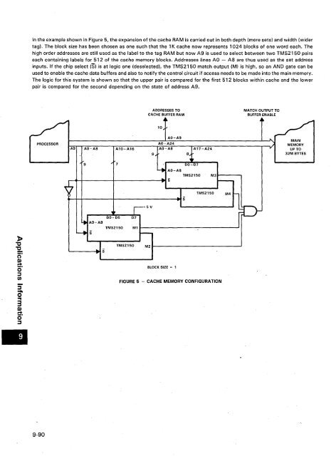
- Page 438 and 439: increments till satisfied. This pro
- Page 442 and 443: »'C"E..crQ)r+0':::Jtil:;-....o...3
- Page 444 and 445: •9-94
- Page 447 and 448: 184LOGIC SYMBOLS1. INTRODUCTIONEXPl
- Page 449 and 450: LOGIC SYMBOLS4.DIAGRAMATIC SUMMARYI
- Page 451 and 452: lOGIC SYMBOLSWhen RAS goes low, it
- Page 453 and 454: Alphanumeric Index, Table of Conten
- Page 455 and 456: MECHANICAL DATAgeneralElectrical ch
- Page 457 and 458: MECHANICAL DATAceramic packages -ce
- Page 459 and 460: MECHANICAL DATAplastic packages (N
- Page 461 and 462: MECHANICAL DATAceramic chip carrier
- Page 463 and 464: Texas InstrumentsSemiconductor Tech
- Page 465 and 466: TI Sales Offices TI DistributorsALA
- Page 468: Printed in U.S.A.•TEXASINSTRUMENT