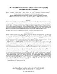
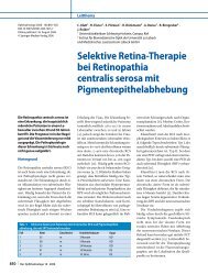
1032 Applied Physics B – Lasers and OpticsFIGURE 15 Temporal evolution <strong>of</strong> the stress amplitude in the center <strong>of</strong> thefocal volume for the same conditions as in Fig. 14The compressive stress generates a stress wave travelinginto the surrounding medium. When the thermal expansioncomes to a rest, inertial forces lead to the generation <strong>of</strong> a relaxationwave that propagates from the periphery <strong>of</strong> the focalvolume towards its center and is focused in the center <strong>of</strong>symmetry. Because <strong>of</strong> the geometrical focusing, it turns intoa tensile stress wave that achieves maximum amplitude at thecenter <strong>of</strong> symmetry.The peak tensile stress amplitude depends strongly onthe shape <strong>of</strong> the heated volume. It is largest for a sphericalshape [155] and much smaller in the present case <strong>of</strong>an elongated ellipsoid. The dependence <strong>of</strong> the compressivestress amplitude on the degree <strong>of</strong> stress confinement t ∗ p wasrelatively strong, but the amplitude <strong>of</strong> tensile stress wavesremained approximately constant when the duration <strong>of</strong> thethermalization pulse was varied between 5ps, 10 ps, and20 ps.A comparison <strong>of</strong> Fig. 14a and b shows that the stress-waveamplitudes outside the focal region are considerably larger inthe radial than in the axial direction. This is a consequence <strong>of</strong>the elongated shape <strong>of</strong> the focal volume. The stress transientsemitted in both directions have a bipolar shape as expectedfor thermoelastic waves. The amplitude <strong>of</strong> the stress transientwhen it leaves the heated region in the radial directionamounts to 25% <strong>of</strong> the peak compressive pressure. This differsfrom the previously analyzed case <strong>of</strong> a top-hat distribution,where the amplitude <strong>of</strong> the compressive wave just outsidethe heated volume amounts to 0.5 times the peak compressivepressure inside that volume [97].Experimental data on stress-wave emission. Measurements<strong>of</strong> the stress waves produced by <strong>femtosecond</strong> optical breakdownat large NA and close to the breakdown threshold arevery challenging because <strong>of</strong> the sub-micrometer size <strong>of</strong> thebreakdown volume and the sub-nanosecond duration <strong>of</strong> thestress transients (Figs. 14 and 15). Hydrophones with sufficientlysmall detector size to resolve the shape <strong>of</strong> the transientclose to their source are not available, and optical techniques[96, 171–173] also do not provide the necessary spatialresolution. Therefore, we performed measurements at smallernumerical <strong>aper</strong>ture (NA = 0.2) to assess the stress amplitudesarising during <strong>femtosecond</strong> optical breakdown.FIGURE 16 Measured pressure vs propagation-distance curve for a stresswave produced by a 100-fs pulse <strong>of</strong> 5-µJ energy(E/E th = 30) focused intodistilled water at NA = 0.2 (16 ◦ full focusing angle). The <strong>laser</strong> wavelengthwas 580 nm. The arrow represents the location <strong>of</strong> the plasma rim as determinedfrom plasma photographs in side view. The p(d) curve was determinedfrom the streak recording <strong>of</strong> the stress-wave emission shown in the insetInvestigations for irradiances well above the breakdownthreshold were done by means <strong>of</strong> streak photography and subsequentdigital image analysis <strong>of</strong> the streak recordings [127,128, 173]. Differentiation <strong>of</strong> the stress wave propagationcurves r(t) obtained from the streak recordings yielded thestress-wave velocity that is related to the pressure amplitudeby the known Rankine–Hugoniot relationship for water [174]if the stress wave has shock-wave properties. The analysisyielded the entire pressure vs distance curve in the immediatevicinity <strong>of</strong> the breakdown region perpendicular to the opticalaxis as shown in Fig. 16.The determination <strong>of</strong> the shock-wave pressure becomesinaccurate for pressure amplitudes below 100 MPa, wherethe deviation <strong>of</strong> the propagation velocity from the sonic velocitybecomes too small to be measured accurately with thestreak technique [173]. Therefore, the streak technique couldonly be applied for shock-wave measurements at energies15–150 times above the breakdown threshold. Stress-waveamplitudes closer to the optical breakdown threshold were determinedindirectly by hydrophone measurements at 6-mmdistance from the focus [127] and extrapolation <strong>of</strong> these datato the plasma rim. We used a PVDF hydrophone (Ceram) witha rise time <strong>of</strong> 12 ns,anactivearea<strong>of</strong>1mm 2 , and a sensitivity<strong>of</strong> 280 mV/MPa (calibrated by the manufacturer up to a frequency<strong>of</strong> 10 MHz). A distance <strong>of</strong> 6mmbetween detector and<strong>laser</strong> focus was required to avoid measurement errors arisingfrom the intersection <strong>of</strong> a spherical shock wave with a planedetector [96]. Measurement results for energies from close tothe breakdown threshold up to 80 times threshold are shownin Fig. 17.The results <strong>of</strong> far-field hydrophone measurements can beextrapolated to the boundary <strong>of</strong> the focal region if the decayconstant n <strong>of</strong> the pressure decay p ∝ r n with increasingpropagation distance r is known. The decay constant was estimatedby comparing pressure values at the plasma rim and inthe far field that were measured at larger <strong>laser</strong> pulse energies.For example, for E = 30 × E th , the pressure at the plasma rim(r = 2.2 µm)is900 MPa (Fig. 16), and the pressure measured
VOGEL et al. <strong>Mechanisms</strong> <strong>of</strong> <strong>femtosecond</strong> <strong>laser</strong> <strong>nanosurgery</strong> <strong>of</strong> cells and tissues 1033FIGURE 17 Stress-wave amplitude for 100-fs pulses and longer pulse durationsas a function <strong>of</strong> the dimensionless <strong>laser</strong> pulse energy E/E th .Thepressure amplitudes were measured by means <strong>of</strong> a hydrophone at 6-mmdistance from the <strong>laser</strong> focusat 6-mm distance is 0.12 MPa (Fig. 17). The resulting decayconstant is n = 1.13. Previous investigations <strong>of</strong> complete p(r)curves for spherical shock waves produced by 30-ps pulses <strong>of</strong>50-µJ energy yielded a very similar constant <strong>of</strong> n = 1.12 overa large range <strong>of</strong> propagation distances [96].An estimate <strong>of</strong> the pressure value at 6-mm distance producedby a 100-fs pulse with threshold energy was obtained byextrapolating the data for E/E th ≥ 1.5 in Fig. 17 to E = E th .It is about 0.008 MPa. The plasma radius at E th was identifiedwith the focal radius <strong>of</strong> 2.2 µm measured using a knife-edgetechnique [127]. A pressure <strong>of</strong> p = 0.008 MPa at 6-mm distancecorresponds to a pressure value <strong>of</strong> 61 MPa at the plasmarim when a decay constant n = 1.13 isassumed,andtoavalue<strong>of</strong> 56 MPa with a decay constant <strong>of</strong> n = 1.12, respectively.Our calculations <strong>of</strong> the thermoelastic stress generation predicta peak pressure <strong>of</strong> 168 MPa at the bubble-formation threshold(see Sect. 6.3, below). According to Fig. 14, the stress transientthat leaves the heated region in the radial direction hasa peak pressure <strong>of</strong> ≈ 25% <strong>of</strong> the maximum compressive amplitudewithin the focal volume. We thus obtain a theoreticalprediction <strong>of</strong> 42 MPa for the amplitude <strong>of</strong> the thermoelasticstress wave at the plasma rim. Considering the uncertainties inthe location <strong>of</strong> the plasma rim and the differences in numerical<strong>aper</strong>ture between experiment and calculation, the agreementbetween experimental results (56–61 MPa) and calculateddata (42 MPa) is very good.Both experiments and calculations reveal that stress confinementin <strong>femtosecond</strong> optical breakdown results in thegeneration <strong>of</strong> high pressure values even though the temperaturerise is only relatively small. In a purely thermal process,a temperature rise to, for example, 200 ◦ C starting fromroom temperature would produce a saturation vapor pressure<strong>of</strong> 1.6MPa. The compressive pressure transient produced bya temperature rise <strong>of</strong> 180 ◦ C under stress-confinement conditionshas an amplitude <strong>of</strong> 220 MPa, which is more than twoorders <strong>of</strong> magnitude larger than the vapor pressure.The situation is different for optical breakdown at longerpulse durations where the stress-confinement condition is notfulfilled. Here, high pressures are always associated with hightemperatures and plasma energy densities. For pulses whichare considerably longer than the thermalization time <strong>of</strong> thefree-electron energy, a dynamic equilibrium between generation<strong>of</strong> free electrons and thermalization <strong>of</strong> their energy is establishedduring the <strong>laser</strong> pulse [81]. This leads to a high value<strong>of</strong> the plasma energy density [80] and a temperature <strong>of</strong> severalthousand degrees Kelvin [175–177]. The duration <strong>of</strong> the resultingshock wave is determined by the time it takes for thehigh pressure within the plasma to decrease during the plasmaexpansion [96], which for NA = 0.9 was found to be about25–40 ns [3]. By contrast, the duration <strong>of</strong> the thermoelasticstress transients is determined by the geometric dimensions<strong>of</strong> the breakdown volume, which are in the sub-micrometerrange. This leads to a duration <strong>of</strong> the stress transients <strong>of</strong> theorder <strong>of</strong> or less than 300 ps (Fig. 15). The short duration <strong>of</strong>these stress waves is correlated with a small energy content(see also Sect. 6.4).6.3 Threshold for stress-induced bubble formationA specific feature <strong>of</strong> the stress transients generatedduring fs optical breakdown is their tensile componentthat is related to the high degree <strong>of</strong> stress confinement duringenergy deposition. The tensile stress makes it possiblethat a cavitation bubble can be generated by a relatively smalltemperature rise in the liquid. The threshold for bubble formationis defined by the temperature rise leading to a crossing<strong>of</strong> the kinetic spinodal, as shown in Fig. 13. For λ = 800 nm,NA = 1.3, and a room temperature <strong>of</strong> 20 ◦ C, the critical temperaturerise and the corresponding critical tensile stress are∆T = 131.5 ◦ C and p =−71.5MPa, respectively. The correspondingcompressive pressure is 168 MPa.The temperature rise <strong>of</strong> 131.5 ◦ C at the threshold for bubbleformation corresponds to an increase in energy density<strong>of</strong> 551 J cm −3 which, according to (18), is produced bya free-electron density <strong>of</strong> ϱ c = 0.236 × 10 21 cm −3 . This electrondensity is less than the breakdown criterion <strong>of</strong> ϱ cr =10 21 cm −3 assumed in our numerical calculations and in mostother theoretical studies <strong>of</strong> plasma formation. The discrepancybetween the threshold values relying on different breakdowncriteria needs to be kept in mind when comparing the results<strong>of</strong> experimental studies, where bubble formation servesas breakdown criterion, with those <strong>of</strong> numerical simulations.The fact that <strong>femtosecond</strong> optical breakdown is associatedwith only a relatively small temperature rise explainswhy plasma luminescence is no longer visible for pulse durationsshorter than about 10 ps [122, 128]. For pulse durationslonger than the thermalization time, large amounts <strong>of</strong> energyare transferred from the free electrons to the heavy particlesduring the <strong>laser</strong> pulse [81], resulting in a temperature <strong>of</strong> severalthousand degrees Kelvin, bubble formation, and a brightplasma luminescence [175–177]. By contrast, a peak temperature<strong>of</strong> 151.5 ◦ C reached at the threshold for bubble formationwith 100-fs pulses is too low to produce black-body radiationin the visible range <strong>of</strong> the optical spectrum. Moreover,the recombination radiation <strong>of</strong> <strong>femtosecond</strong>-<strong>laser</strong>-producedplasmas is weak because only one ‘set’ <strong>of</strong> free electrons is producedthat recombines after the end <strong>of</strong> the <strong>laser</strong> pulse. Theenergy density will remain small also at energies above thethreshold for bubble formation because <strong>of</strong> the shielding <strong>of</strong> thefocal region by plasma formation upstream <strong>of</strong> the focus [80,126, 136–139] (see Sect. 3.2). Therefore, bubble formation is