Create successful ePaper yourself
Turn your PDF publications into a flip-book with our unique Google optimized e-Paper software.
<s<strong>tr</strong>ong>72</s<strong>tr</strong>ong> <s<strong>tr</strong>ong>Series</s<strong>tr</strong>ong>Servovalves
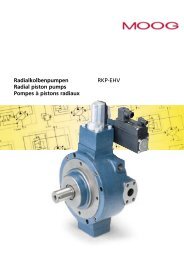
<s<strong>tr</strong>ong>72</s<strong>tr</strong>ong> SERIESTWO STAGE SERVOVALVES<s<strong>tr</strong>ong>72</s<strong>tr</strong>ong> SERIES SERVOVALVESThe <s<strong>tr</strong>ong>72</s<strong>tr</strong>ong> <s<strong>tr</strong>ong>Series</s<strong>tr</strong>ong> flow con<strong>tr</strong>olservovalves are throttle valvesfor 3 and preferably 4-wayapplications.They are a highperformance, two-stage designthat covers the range of ratedflows from 25 to 60 gpm at1000 psi valve drop.The outputstage is a closed center, fourwaysliding spool.The pilotstage is a symme<strong>tr</strong>ical doublenozzleand flapper, driven bya double air gap, dry torquemotor. Mechanical feedback ofspool position is provided by acantilever spring.The valvedesign is simple and rugged fordependable, long life operation.These valves are suitable forelec<strong>tr</strong>ohydraulic position,speed, pressure or force con<strong>tr</strong>olsystems with high dynamicresponse requirements.Principle of operationAn elec<strong>tr</strong>ical <s<strong>tr</strong>ong>com</s<strong>tr</strong>ong>mand signal(flow rate set point) is appliedto the torque motor coils, andcreates a magnetic force whichacts on the ends of the pilotstage armature.This causes adeflection of armature/flapperassembly within the flexuretube. Deflection of the flapperres<strong>tr</strong>icts fluid flow through onenozzle which is carried throughto one spool end, displacingthe spool.Movement of the spool opensthe supply pressure port (P) toone con<strong>tr</strong>ol port, while simultaneouslyopening the tankport (T) to the other con<strong>tr</strong>olport.The spool motion alsoapplies a force to the cantileverspring, creating a restoringtorque on the armature/flapperassembly. Once the restoringtorque be<s<strong>tr</strong>ong>com</s<strong>tr</strong>ong>es equal to thetorque from the magneticforces, the armature/flapperassembly moves back to theneu<strong>tr</strong>al position, and the spoolis held open in a state of equilibriumuntil the <s<strong>tr</strong>ong>com</s<strong>tr</strong>ong>mand signalchanges to a new level.In summary, the spool positionis proportional to the inputcurrent and with constantpressure drop across the valve,flow to the load is proportionalto the spool position.VALVE FEATURES➣ 2-stage design with dry torque motor➣ Low friction double nozzle pilot stage➣ High spool con<strong>tr</strong>ol forces➣ High dynamics➣ Rugged, long-life design➣ High resolution, low hysteresis➣ Completely set-up at the factory➣ Optional fifth port for separate pilot supply➣ Field replaceable pilot stage filterThe actual flow is dependentupon elec<strong>tr</strong>ical <s<strong>tr</strong>ong>com</s<strong>tr</strong>ong>mand signaland valve pressure drop.Theflow for a given valve pressuredrop can be calculated usingthe square root function forsharp edge orifices:Q = QN∆p∆pNQ [gpm] = calculated flowQN [gpm] = rated flow∆p [psi] = actual valvepressure drop∆pN [psi] = rated valvepressure dropThis catalog is for users with technicalknowledge.To ensure that all necessarycharacteristics for function and safety of thesystem are given, the user has to check thesuitability of the products described here.In case of doubt, please contact Moog Inc.In<strong>tr</strong>insically safe valve versions are available for use in hazardous locations.Specific models are certified to FM,ATEX, CSA, and TIIS standards. Contact the factoryfor details.2
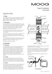
<s<strong>tr</strong>ong>72</s<strong>tr</strong>ong> SERIESGENERAL TECHNICAL DATAOperating Pressureports P, X,A and B up to 3,000 psi*port Tup to 3,000 psiTemperature RangeFluid -40°F to 275°FAmbient -40°F to 275°FSeal Material Viton **Operating FluidCompatible with <s<strong>tr</strong>ong>com</s<strong>tr</strong>ong>monhydraulic fluids, other fluidson request.Re<s<strong>tr</strong>ong>com</s<strong>tr</strong>ong>mended viscosity 60-450 SUS @ 100°FSystem Fil<strong>tr</strong>ation: High pressure filter (without bypass,but with dirt alarm) mounted in the main flow and if possible,directly ups<strong>tr</strong>eam of the valve.Class of Cleanliness: The cleanliness of the hydraulic fluidgreatly effects the performance (spool positioning, high resolution)and wear (metering edges, pressure gain, leakage) of the servovalve.Re<s<strong>tr</strong>ong>com</s<strong>tr</strong>ong>mended Cleanliness ClassFor normal operation ISO 4406 < 14/11For longer life ISO 4406 < 13/10Filter Rating re<s<strong>tr</strong>ong>com</s<strong>tr</strong>ong>mendedFor normal operation ß10 ≥ 75 (10 µm absolute)For longer lifeß5 ≥ 75 (5 µm absolute)Installation Operations Any position, fixed or moveable.Vibration30 g, 3 axesWeightShipping Plate* Maximum special order is 5,000 psi** Other seal material upon request7.75 lb. (3.52 kg)Delivered with an oil sealedshipping plate.1000100101100 1000 10000Valve Flow DiagramValve flow for maximum valve opening (100% <s<strong>tr</strong>ong>com</s<strong>tr</strong>ong>mandsignal) as a function of the valve pressure drop.604025P B T A3
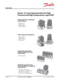
<s<strong>tr</strong>ong>72</s<strong>tr</strong>ong> SERIESTECHNICAL DATAModel . . .Type <s<strong>tr</strong>ong>72</s<strong>tr</strong>ong> . . . . .Mounting Pattern ISO 103<s<strong>tr</strong>ong>72</s<strong>tr</strong>ong> - 06 - 05 - 0 -92Valve Body Version4-way2-stage with spool-bushing assemblyPilot StageNozzle/Flapper, High flowPilot Connection Optional Internal or ExternalRated Flow (± 10%) at ∆pN = 1,000 psi [gpm] 25 40 60Response Time* [ms] 16 26 40Threshold* [%] < 1.5%Hysteresis* [%] < 4.0%Null Shift at ∆T = 100°F [%] < 4.0%Null Leakage Flow* max. [gpm] 0.55 to 1.30* Measured at 1,000 psi pilot or operating pressureStep Response100S<strong>tr</strong>oke (% of max)80604020451263Ps = 1000 PSI (70 bar)1= <s<strong>tr</strong>ong>72</s<strong>tr</strong>ong>-1012 = <s<strong>tr</strong>ong>72</s<strong>tr</strong>ong>-1023 = <s<strong>tr</strong>ong>72</s<strong>tr</strong>ong>-103Ps = 3000 PSI (210bar)4 = <s<strong>tr</strong>ong>72</s<strong>tr</strong>ong>-1015 = <s<strong>tr</strong>ong>72</s<strong>tr</strong>ong>-1026 = <s<strong>tr</strong>ong>72</s<strong>tr</strong>ong>-1030010 20Time (ms)30 40Typical characteristiccurves with ±40% and ±100%input signal, measured at 3,000pilot or operating pressure.Standard ValvesAmplitude Ratio (dB)+20-2-4-6-8-107103000 psi DTE-24-63000 psi DTE-24-6at 100˚F (38˚C)at 100˚F (38˚C)Rated Current:100-8 Rated Current:100-8±40%±40%±100% 80-10±100%80-1015 20 30 50 70 100 150 2006040200Phase Lag (degrees)Amplitude Ratio (dB)+20-2-471015 20 30 50 70 100 150 2006040200Phase Lag (degrees)Amplitude Ratio (dB)+20-2-473000 psi DTE-24at 100˚F (38˚C)Rated Current:±40%±100%1015 20 30 50 70 100 150 200100806040200Phase Lag (degrees)Frequency (Hz)Frequency Responseof 25 gpm ServovalvesFrequency (Hz)Frequency Responseof 40 gpm ServovalvesFrequency (Hz)Frequency Responseof 60 gpm Servovalves4
<s<strong>tr</strong>ong>72</s<strong>tr</strong>ong> SERIESINSTALLATION DRAWINGS4 MOUNTING HOLES.406 [10.31] THRU1.81[46.0]3.62 MAX[92.0]2.875[73.03]1.437[36.50]3.375[85.73]1.687[42.85]2.03[51.6]4.06[103.1]3.05[77.5]FIELD REPLACEABLEFIRST STAGE FILTER .86[22.0] 1.73[43.9]2.26[57.4]PIN DPIN CMECHANICALNULL ADJUSTPIN APIN BOPTIONALMAGNETICNULL ADJUST5.15[130.8]2.24[56.9]2.75[69.9]1.37[34.8]1.50[38.1]3.28[83.3] 4.48[113.8]MAX2.38 [60.5]3.69 DIA TYP[93.7]PLOCATING PIN.25 [6.4].28[7.1]6.70[170.2]TYPICAL SUBPLATE MANIFOLD1.50021.604X.406 THRU.609 .60.014 MPORT PER SAE J1926.4375-20 UNF-2BDASH 4 STR THD O-RINGBOSS (.25 TUBE OD REF)5.004X .375-16 UNC-2B THD.013 M2.504.2502.125CONTROL PORT B4X .688.014 M2.0001.000.250 AUXILIARY PILOTPRESSURE PORT X.014 M4X PORT PER SAE J19261.625-12 UN-2BDASH 20 STR THD O-RINGBOSS (1.25 TUBE OD REF)2.1254.2502.0001.000.7501.437(36.5)2.875(73)2.50RETURN PORT T1.687(42.9).750CONTROL PORT A1.500VALVE MOUNTSO N THIS MANIFOLDSURFACEPRESSURE PORT P1.254 PL.39 .30.014 M2.50323.375(85.7).002Null Adjust: Flow out of Con<strong>tr</strong>olPort B will increase with clockwiserotation of null adjust screw(3/32 hex key).The mounting manifoldmust conform toISO 103<s<strong>tr</strong>ong>72</s<strong>tr</strong>ong>-06-05-0-92.Surface to which valve ismounted requires a√ 32 [∆∆]finish, flat within 0.002[0.05] TIR.Standard elec<strong>tr</strong>ical connectormates with MS3106F14S-2Sor equivalent.P5.005
<s<strong>tr</strong>ong>72</s<strong>tr</strong>ong> SERIESELECTRICAL CONNECTIONSRated current andcoil resistanceA variety of coils are availablefor <s<strong>tr</strong>ong>72</s<strong>tr</strong>ong> <s<strong>tr</strong>ong>Series</s<strong>tr</strong>ong> Servovalves,which offer a wide choice ofrated current. See Table I.TABLE 1NominalResistancePer Coil at77ºF (25ºC) ΩCoil connectionsA four-pin elec<strong>tr</strong>icalconnector (that mateswith an MS3106F14S-2S)is standard. All four torquemotor leads are availableat the connector so externalRe<s<strong>tr</strong>ong>com</s<strong>tr</strong>ong>mended Rated Current–mAParallel,Differential or SingleCoil Operationconnections can be made forseries, parallel or differentialoperation.<s<strong>tr</strong>ong>72</s<strong>tr</strong>ong> <s<strong>tr</strong>ong>Series</s<strong>tr</strong>ong> Servovalvescan be supplied on specialorder with other connectors.Approximate Coil Inductance*–Henrys<s<strong>tr</strong>ong>Series</s<strong>tr</strong>ong> Coils Single Coils <s<strong>tr</strong>ong>Series</s<strong>tr</strong>ong> Coils Parallel CoilsServoamplifierThe servovalve respondsto input current, thereforea servoamplifier that hashigh internal impedance(as obtained with currentfeedback) should be used.This will reduce the effectsof coil inductance and willminimize changes due tocoil resistance variations.80±40±200.220.660.18200±15±7.50.<s<strong>tr</strong>ong>72</s<strong>tr</strong>ong>2.200.591000±8±43.209.702.60* Measured at 50 HzELECTRICALCONNECTIONS(Examples with typical <s<strong>tr</strong>ong>72</s<strong>tr</strong>ong> series coils)Parallel<s<strong>tr</strong>ong>Series</s<strong>tr</strong>ong>SingleA B C D A B C D A B C DCoil ResistanceRated CurrentElec<strong>tr</strong>ical PowerConnections for Valve OpeningP ➧ B, A ➧ T[Ω][mA][W]100±15.023A and C (+)B and D (-)400±7.5.023A (+), D (-)B and C connected200±15.045A (+), B (-)or C (+), D (-)Note: Before applying elec<strong>tr</strong>ical signals, the pilot stage has to be pressurized.ExternalProcedure to Configure a <s<strong>tr</strong>ong>72</s<strong>tr</strong>ong> <s<strong>tr</strong>ong>Series</s<strong>tr</strong>ong> Servovalve for External Pilot Operation1. Remove the set screw from the “X” port on the base of the valve using a 1/8'' Allen wrench.2.Thread a #2-56 screw into the o-ring plug that is now visible and remove it from the “X” port.3. Remove the four (4) socket head cap screws and lockwashers that retain the cover plate for thefield replaceable filter, using a 3/16'' Allen wrench.4. Use one of the screws to pull the filter and filter housing out of the filter cavity of the body.The filter housing has two (2) o-rings on its O.D.The housing will <s<strong>tr</strong>ong>com</s<strong>tr</strong>ong>e part way out, then stopafter the second o-ring passes the internal relief in the body.At this time it may be easier to removethe visible o-ring and carefully pry the housing and filter out with two opposing flat blade screwdrivers, than to continue pulling on the screw. Be careful not to damage the o-ring groove.5.A bore will be visible inside the body cavity where the o-ring plug must be inserted.6. Retain the o-ring plug with the set screw.7. Re-install the filter and filter housing in the cavity.8. Re-install the filter cover, retaining screws and lockwashers.Torque the screws to 85 in-lbs.InternalPRESSURE PORT6X PORT