A Model of Gas Injection into a Blast Furnace Tuyere - Sintef
A Model of Gas Injection into a Blast Furnace Tuyere - Sintef
A Model of Gas Injection into a Blast Furnace Tuyere - Sintef

Create successful ePaper yourself
Turn your PDF publications into a flip-book with our unique Google optimized e-Paper software.
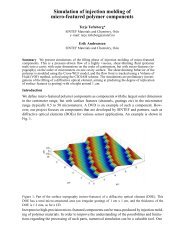
2000Temperature [C]195019001850180017501700165016001550Mean temperature <strong>of</strong> the blast15005 000 7 500 10 000 12 500 15 000 17 500 20 000Coke oven gas flow [nm 3 /h]Figure 7Mean temperature <strong>of</strong> the blast versus cokeoven gas flow at the end <strong>of</strong> the tuyere pipe fora system with two injection lancesAs shown in figure 7, the mean temperature <strong>of</strong> the blasthas a peak when injecting 15 000 nm 3 /h <strong>of</strong> coke oven gasusing two injection lances. <strong>Injection</strong> <strong>of</strong> more coke ovengas in the tuyere will also reduce the mean temperature <strong>of</strong>the blast. By comparing figure 6 and figure 7 it can beseen that there are big differences in the temperaturelevels for the two cases. More specifically, it differs about270 °C for the maximum blast temperature. Figure 8shows the velocity pr<strong>of</strong>ile for a velocity <strong>of</strong> 200 m/s in theblast for both cases.Inlet <strong>of</strong> the injection lancesOne injection lanceInlet <strong>of</strong> thelanceInlet <strong>of</strong> thetuyereFigure 9The different injection angles <strong>of</strong> the lance usedin the model for two injection lances.More specifically, angles between 10° to 20° degreesrelative to the tuyere pipe axis have been studied. Thecoke oven gas injection amount in this parameter studycorresponds to 12 500 nm 3 /h for all simulations. A contourplot <strong>of</strong> the velocity pr<strong>of</strong>ile at 250 m/s in the blast is shownin figure 10.Inlet <strong>of</strong> the injection lances<strong>Tuyere</strong> inletXZ20°10°<strong>Tuyere</strong>outlet<strong>Tuyere</strong>outlet<strong>Tuyere</strong> inlet<strong>Tuyere</strong>outlet0 0.02 0.04 0.06 0.08 0.1 0.12 0.14 0.16 0.18 0.2<strong>Tuyere</strong> lenghtTwo injection lancesFigure 10 Contour plot <strong>of</strong> the velocity pr<strong>of</strong>ile at 250 m/sin the blast, when comparing 10 and 20 degreeangle <strong>of</strong> the injection lancesFigure 80 0.02 0.04 0.06 0.08 0.1 0.12 0.14 0.16 0.18 0.2<strong>Tuyere</strong> lengthComparison <strong>of</strong> the velocity pr<strong>of</strong>ile for one andtwo lances at 200 m/s in the blast (Coke ovengas flow, 5 000 nm 3 /h)As can be seen in the figure, the velocity pr<strong>of</strong>ile is muchmore uniform when using a two-lance configurationcompared to a single-lance configuration.<strong>Injection</strong> AngleThe effect <strong>of</strong> the injection angle <strong>of</strong> the lance, in relation tothe tuyere axis, on the predicted gas conditions at thetuyere outlet has also been studied. A series <strong>of</strong> simulationshave been performed where the angles <strong>of</strong> the lances werechanged partly based on practical experience. Anillustration <strong>of</strong> the different lance angles which have beenmodeled is shown in figure 9.The change in the velocity pr<strong>of</strong>ile for lance anglesbetween 10° and 20° is very small. The pr<strong>of</strong>ile for 250 m/sfor the 20° angle are close to the pr<strong>of</strong>ile for the 10° angle.In order to determine the relation between the oxidant andthe fuel at different positions along the tuyere, a nondimensionvariable f, called the mixture fraction may bedefined, in terms <strong>of</strong> unit mass, m, as:fm − mo= (6)ml− mowhere the suffix o denotes the oxidant stream and l denotethe fuel stream. The value <strong>of</strong> f equals 0 if the mixture at aspecific position contains only oxidant and equals 1 if itcontains only fuel. In figure 11, contour plotscorresponding to a value <strong>of</strong> 0.1 for the mixture fraction, f,has been plotted for lance angles <strong>of</strong> 10° and 20°,respectively.4
<strong>Tuyere</strong> inletInlet <strong>of</strong> the injection lances20°10°<strong>Tuyere</strong>outlet0 0.02 0.04 0.06 0.08 0.1 0.12 0.14 0.16 0.18 0.2<strong>Tuyere</strong> lenghtFigure 11 Contour plot <strong>of</strong> the non-dimensional variable ffor a certain value <strong>of</strong> 0.1 in the blast, whencomparing a 10° and a 20° degree angle <strong>of</strong> theinjection lancesThe flame is slightly longer for the case with a 10° lanceangle. This indicates that the combustion is occurringearlier than for the case with a 20° lance angle, but itshould be noted that the differences are quite small.CONCLUSIONA mathematical model has been developed for an injectiontuyere in a blast furnace to simulate the combustion, wheninjecting reducing gas. The fluid flow is solved based onfundamental transport equations in combination with thestandard k-ε turbulence model. The chemical reactions aremodeled using a two-step reaction scheme with threepossible reactions that can occur. Furthermore, an EBUmodel is used to describe the rate <strong>of</strong> the reactions. Themodel has been used to predict velocity, temperature andcomposition data <strong>of</strong> the blast inside the tuyere. Based onthe conditions in the study, the specific conclusions can besummarized as follows:• The mean temperature <strong>of</strong> both the BOF gas and thecoke oven gas increases with the distance from thelance tip. The temperature increase is higher for thecoke oven gas due to a more complete combustion andthe higher heating value <strong>of</strong> the gas.• When using one injection lance, the maximuminjecting amount is 10 000 nm 3 /h. If the injectionamount is higher, part <strong>of</strong> the gas will not combust inthe tuyere but will enter <strong>into</strong> the blast furnaceunburned.• For two injection lances, the maximum injectingamount is increased to 15 000 nm 3 /h, due to bettercombustion conditions. The conditions are better asthe inlet velocity <strong>of</strong> the gas is lower, the turbulence inthe tuyere pipe is enhanced, and also more <strong>of</strong> the cokeoven gas is in contact with the blast, i.e. the reactingarea is bigger.• The effect <strong>of</strong> varying the injection angles <strong>of</strong> the lanceson the predicted results is not obvious.REFERENCES1. ANDAHAZY D., LÖFFLER G., WINTER F.,FEILMAYR C. and BURGLER T., (2003),“<strong>Model</strong>ling coke oven gas and COG/BOF gasinjection <strong>into</strong> the blast furnace”, IFRF OnlineCombustion Journal Stockholm, Sweden, October.2. WAKELIN, D.H. et al., (2000), ”High productivityand high natural gas injection in U.S.A”, 4 th ECIC2000 Paris ATS – RM.3. AGARWAL J., BROWN F., CHIN D., STEVENS G.and SMITH D., “Injecting coal and natural gas: Whichone? How much?, ” Iron Age New Steel 1996:12 p.12.4. MADDALENA, F.L., TERZA R.R., SOBEK T.F. andMYKLEBUST K.L., (1995), ”Coke Oven <strong>Gas</strong><strong>Injection</strong> <strong>into</strong> <strong>Blast</strong> <strong>Furnace</strong>s”, ISS 54 th Iron makingConference Nashville.5. BUERGLER T., BRUNNBAUER G., FERSTL A.,HELLBERG P., SKOELD B.E ., WIEDER K.,WURM J. and MILLNER R., (2004) ,”Development<strong>of</strong> a Reducing <strong>Gas</strong> <strong>Injection</strong> Technology at <strong>Blast</strong><strong>Furnace</strong> 5 and 6 <strong>of</strong> VOESTALPINE STAHL GMBH,SCANMET II”, 2 nd International Conference onProcessing Development in Iron and SteelmakingLuleå, Sweden, June 6-9.6. LAUNDER B.E. and SPALDING D.B., (1972),“Mathematical models <strong>of</strong> turbulence”, Academicpress, London, England.7. JÖNSSON P. and JONSSON L., “A model <strong>of</strong> a gasstirredladle”, MEFOS, Scandinavian Journal <strong>of</strong>Metallurgy 1995:24 p.194.8. KEE R., RUPLEY F., MEEKS E. and MILLER J.,“CHEMKIN-III: A FORTRAN Chemical KineticsPackage for the Analysis <strong>of</strong> <strong>Gas</strong>-Phase Chemical andPlasma Kinetics”. Sandia National LaboratoriesLivermore, CA 94551-0969.9. SPALDING, D.B., (1997), ”PHOENICSEncyclopaedia ”, CHAM London10. SPALDING, D.B., (1971)., “Mixing and chemicalreaction in confined turbulent flames”, 13thInternational Symposium on Combustion, TheCombustion Institute, Pittsburgh.Finally, it should be pointed out that the conditions in theraceway are very complex and also influence theconditions in the tuyere and hence the combustion <strong>of</strong> thereducing gases.5