4500 IOM - Eastech Flow Controls
4500 IOM - Eastech Flow Controls
4500 IOM - Eastech Flow Controls
- No tags were found...

Create successful ePaper yourself
Turn your PDF publications into a flip-book with our unique Google optimized e-Paper software.
SCOPE OF MANUALThis manual contains information concerning theinstallation, operation and maintenance of the Series <strong>4500</strong>Compu-Sonic flow meter. To ensure proper performanceof the meter, the instructions given in this manual shouldbe thoroughly understood and followed.Keep the manual in a readily accessible location forfuture reference.Changes and additions to the original edition of thismanual will be covered by a "CHANGE NOTICE"supplied with the manual.MODEL <strong>4500</strong> COMPU-SONICTABLE OF CONTENTSPagePageUnpacking and Inspection................................. 1-1 Window Spool .................................................... 3-10HS3 "Hot Shot" Sensor....................................... 3-11INSTALLATION PROCEDURE Instream Refracting Sensor................................. 3-14Wetted Sensor with Hoop................................... 3-15ElectronicsEnclosure Mounting and Wiring....................... 2-1 OPERATIONOutdoor Enclosure ............................................ 2-6<strong>4500</strong>R+ (with Recorder) ................................... 2-6Splice Procedure ............................................... 2-7 Menu Functions...................................................... 4-1Troubleshooting Guide........................................... 5-1Sensors Illustrated Parts List ............................................... 6-1Sensor & Mounting Hardware.......................... 3-2V-Shot Strap-on ................................................ 3-3Z-Shot Strap-on................................................. 3-42 Inch Strap-on.................................................. 3-8Hi-Temp Strap-on ............................................. 3-9UNPACKING &INSPECTIONTo avoid damage in transit, <strong>Eastech</strong> Badger productsare shipped to the customer in special shippingcontainers. Upon receipt of the product, perform thefollowing unpacking and inspection procedures:NOTE: If damage to the shipping container is evidentupon receipt, request the carrier to be present when theproduct is unpacked.a. Carefully open the shipping container followingany instructions that may be marked on the box. Removeall cushioning material surrounding the product andcarefully lift the product from the container.Retain the container and all packing material for possibleuse in reshipment or storage.b. Visually inspect the product and applicableaccessories for any physical damage such as scratches,loose or broken parts, or any other sign of damage thatmay have occurred during shipment.NOTE: If damage is found, request an inspection by thecarrier's agent within 48 hours of delivery and file a claimwith the carrier. A claim for equipment damage in transit isthe sole responsibility of the customer.1-111-01941288
INSTALLATION BACKHOUSINGFRONTHOUSINGGASKETELECTRONIC ENCLOSUREThe Series <strong>4500</strong> electronics is housed in a rugged,NEMA 4X rated, polycarbonate enclosure which can bewall mounted. Supplied with each unit are two 1/4-20 x3/4 inch mounting screws for use with lead inserts, two1/4-20 x 3/4 inch sheet metal screws for other wallmaterials, and two "O" rings necessary to maintain theNEMA 4X rating of the enclosure.FIGURE 2-1HOUSINGHEX BOLTMOUNTINGSCREW AND"O" RINGWhen mounting the Series <strong>4500</strong> electronics, select alocation that has good ventilation, temperature within themeter's specification, not in direct sunlight, not subject toflooding, protection from accidental shock, and providesaccessibility to operate and service the meter.RIBBON CABLECONN.ENCLOSURE MOUNTINGFIGURE 2-2To mount the enclosure, using the 5/32 inch Allenwrench supplied in the mounting hardware package,loosen and remove all four hex bolts in the front of thehousing (see Figure 2-1). Separate the front and backhousings. CAUTION: THERE ARE TWO SIGNALWIRES ON THE FRONT HOUSING AND A RIBBONCABLE ON THE POWER SUPPLY BOARD THAT WILLNEED TO BE DISCONNECTED WHEN RE-MOVINGTHE FRONT HOUSING (SEE FIGURE 2-2). Place thefront housing in a protected area so it will not be damagedwhile mounting the back housing.To mount the back housing, drill two holes in the wall4.5 inches apart (centerline to centerline, see Figure 2-3).The size of the holes will depend on whether lead insertsare used or the mounting screws are screwed directly inthe wall. Select the appropriate screws and place the "O"rings on the screws. With a 3/8 inch hex head driver,secure the back housing to the wall. Since the power supplyboard is in the back housing, care should be taken to preventdamaging any components on the board.4.5 "CL-CLSIGNALWIREPOWERSUPPLYBOARD"O" RINGMOUNTINGSCREWFIGURE 2-32-1
WIRING CONNECTIONSThe Series <strong>4500</strong> electronics enclosure is provided withthree holes for 1/2 inch NPT conduit fittings. These holesare on the bottom of the back housing of the enclosureand allow entry for the 115 or 230 VAC power wires,sensor cables and 4-20 mADC signal output wires. TheAC power lines as well as the sensor cables must be in separatemetallic conduits or the operation of the meter could beaffected.The terminals on the power supply board will accept 14to 22 gauge wire. A small common screw driver will berequired to loosen and tighten the screws. The connectorssnap off the board to facilitate the inserting of the wireseasier.Power supply connections (Figure 2-4). Terminalconnector TB1 is for the 115 VAC connections. Terminal1 is the high side (black wire) connection. Terminal 2 isthe low or neutral side (white wire) connection. Terminal3 is the earth ground (green wire) connection.Terminal connector TB2 is for the 12 VDC externalbattery power connections and the 4-20 mA output.Terminal 1 is the positive (+) connection and Terminal 2is the negative (-) connection for the battery (12 VDC)power input. The voltage range for this input is 9 VDC to14 VDC. This input will operate the meter but not the 4-20 mA output. Terminals 3 and 4 of TB2 are for the 4-20mA output. Terminal 3 is the positive (+) connection andTerminal 4 is the negative (-) connection. The maximumload resistance when operating the meter with AC poweris 1000 ohms.To power the 4-20 mA output when operating with DCpower, the DC power must be connected in series withthe load (recorder) as shown below.TB24-20 mAOutput1 2 3 4Recorder orOther deviceVDCBACK HOUSINGPOWER SUPPLY BOARDDOTSIGNALWIRESF10.1ATB1HILOGNTB 2TB4UPSTREAMSENSORBAT 4-20MADOWNSTREAMSENSORSW1 SW2 SW3 SW4TP1 +14VDCTP2 GROUNDTP3 +40VDCTP4 +-40VDCTP5 + 4-20 mATP6 Power+45-50VDC4-20 mATest PointsFIGURE 2-4BACK HOUSING POWER SUPPLY2-2
The size of the DC supply will depend on the loadresistance the 4-20 mA is driving. It requires 8 VDC topower the 4-20 mA circuitry. The equation to determinethe required voltage for a load is:V = (R * .02) + 8where:V = Power supply in VDCR = Resistance of load in ohmsFor example, if the device connected to the 4-20 mAoutput has a resistance of 250 ohms, then the requiredpower supply is 13 VDC.V = (250 * .02) + 8V = 13 VDCThe terminal strip TB3 has the connections for the fourrelay outputs. These are labeled SW1 through SW4 andrepresent relays 1 through 4 respectively. These relays areSPDP and are rated for 1 amp at 24 VDC or 0.5 amp at120 VAC.The output of these relays will depend on theassignment given to them in the Calibration Mode. Referto Page 4-7 for further details regarding the assignment ofspecific functions to the relays.There are two test point jacks on the bottom of the casebetween the third and fourth conduit holes. These allowthe checking of the 4-20 mA output with a current meter.A load must be connected to the 4-20 mA outputterminals. Do not use these jacks as a second 4-20 mA outputor the normal output will be affected.1-3/4"1-3/8"1-1/8"3/4" 1/2" 1/2"1/4"3/8"1/4"3/8"RemoveoutercoverRemoveoutershieldRemovemiddlecoverRemovemiddleshieldRemoveinnercoverCompletedcable1 2 3 4 5 6FIGURE 2-5SENSOR CABLE PREPARATIONSensor cable connections. Before pulling the sensorcables through the conduit, mark the ends of the cables toindicate which is the upstream and downstream sensorcable. Leave approximately 8 inches of cable extendingfrom the conduit in the enclosure. Refer to Figure 2-5 andprepare the cable ends in the following manner.1. Remove outer cable cover. Measure 1-3/4" fromthe end of the cable. With a cutting tool, carefully cutthrough the outer covering completely around the cablemaking sure not to cut into the outer shield. Make anothercut from the first cut to the end of the cable and removethe outer cover.2. Remove outer shield. Measure 1-3/8" from the endof the cable with a pair of small cutters, cut the shieldaround the cable at the measured point and remove the cutoff shield.3. Remove middle cover. Measure 1-1/8" from theend of the cable. With a cutting tool, carefully cut throughthe middle covering completely around the cable makingsure not to cut into the middle shield. Make another cutfrom the first cut to the end of the cable and remove themiddle cover.4. Remove middle shield. Measure 3/4" from the endof the cable. With a pair of small cutters, cut the shieldaround the cable at the measured point and remove the cutoff shield.2-3
5. Remove inner cover. Measure 1/2" from the end ofthe cable. With a cutting tool or pair of wire strippers,carefully cut the inner covering completely around thecable, making sure not to cut into the center conductorand remove the inner cover.After the ends of the cables have been prepared, loosenthe screws on Terminals 1 and 2 of TB4 on the backhousing power supply and remove the two pairs ofclamps below TB4. Take the upstream cable and insertthe center conductor into Terminal 1 and tighten thescrew. Slightly pull on the cable to ensure the wire issecured to the terminal. Take the downstream cable andinsert the center conductor into Terminal 2 and tighten thescrew. Slightly pull on the cable to ensure the wire issecured to the terminal.Place the two pair of clamps over the middle and outershields and secure them into place. Verify that the clampsare making good contact with the shields and that nowires of the shields are extending beyond their ownclamp down area.Front housing installation. After the wiring of the backhousing is completed, the front housing can bereinstalled. The gasket is attached to the front housing toensure proper alignment for maintaining a good seal.Refer to Figure 2-6. On the front housing there is aprotective cover for the electronic boards that also has thedrawing for the wiring connections of the unit. Connectthe ribbon cable plug S1 coming from the front housinginto the socket connector P1 on the power supply in theback housing.Insert the two signal wires coming from the powersupply board in the back housing into the connectors onthe electronic board in the front housing. One of thesignal wires has a white dot marked on it and should beinserted into the connector next to the dot indicated on theprotective cover drawing. Secure the front housing to theback housing with the four hex bolts.Page 2-6 shows the wiring for the Series <strong>4500</strong> mountedin the 3000+ recorder and in an outdoor enclosure withheater and thermostat.2-4
S1FRONT HOUSINGCONNECTOR KEYCOMPU-SONIC FLOWMETERMADE IN USA <strong>4500</strong>MAGNETUPSTREAMSENSORDOWNSTREAMSENSORBACK HOUSINGPOWER SUPPLY BOARDDOTSIGNALWIRESF10.1ATB1HILOGNTB 2TB4UPSTREAMSENSORBAT 4-20MADOWNSTREAMSENSORSW1 SW2 SW3 SW4TP1 +14VDCTP2 GROUNDTP3 +40VDCTP4 +-40VDCTP5 + 4-20 mATP6 Power+45-50VDC4-20 mATest PointsFIGURE 2-62-5
117VAC FROM CUSTOMER TERMINAL TO <strong>4500</strong>AND RECORDER TERMINALS AND 4-20 MADCSIGNAL FROM <strong>4500</strong> TO RECORDER ARE PRE-WIREDAT THE FACTORYRECORDER ACCESSORY OUTPUTSSEE RECORDER MANUAL PG. 4UPSTREAM &DOWNSTREAMSENSOR TERMINATION(SEE MANUAL PG. 2-3& 2-4)HI LO GND117 VACCUSTOMER INPUTFIGURE 2-7SERIES <strong>4500</strong> IN 3000+ RECORDERWIRING DIAGRAMCDUPSTREAM &DOWNSTREAMSENSOR TERMINATION(SEE MANUAL PG. 2-3 & 2-4)ABOUTDOOR ENCL.DIMENSIONSA= 8.00"B= 10.75"C= 12.75"D= 13.50"E= 5.62"EHI LO GND117 VACCUSTOMER INPUT117VAC FROMCUSTOMERTERMINAL TO <strong>4500</strong>ARE PRE-WIREDAT FACTORYFIGURE 2-8SERIES <strong>4500</strong> OUTDOOR ENCLOSUREWIRING DIAGRAM2-6
TRIAX CABLE SPLICE PROCEDUREMaterials Required* 4 pigtail cap crimps (wire size 18-12)* 2 center conductor cap crimps (wire size 22-14)* 1 roll of electrical tape* 2 epoxy resin envelopesCrimp tool (customer supplied)Knife (customer supplied)Pointed tool (customer supplied)Junction box (customer supplied)A cable connection kit may be purchased through <strong>Eastech</strong>Badger that will include the * items above (Part # 541874).Trim each of the four cables at the junction box to 9 inches inlength. Each of the four cables can now be prepared asdescribed in the sequence following:A B C D E F GUsing a knife, trim two inches of the outer jacket from eachcable. The wire braid beneath the outer jacket must not be cut.See "A".Using a pointed tool, carefully comb out the outer braid ofeach cable as shown in "B". Form the combed braid into apigtail dressed to the side of the cable as shown in "C".Trim 1 inch of the inner jacket from each of the cables asshown in "D". Again, use care not to cut the inner braid beneaththe inner jacket.Using a pointed tool, carefully comb out the inner braid "E"and form into a pigtail dressed to the same side of the cable asouter pigtail in "F".Remove 1/2 inch of insulation from the inner conductor ofeach cable. Cut the outer pigtail to the same length as the innerpigtail on each cable. "G" depicts the completed preparation.FIG 1 FIG 2Cable TerminationPull cables approximately 18 inches outside of junction box.Select one sensor cable and one cable from the electronicenclosure and place them side by side as shown in Fig. 1. Twisteach cable's outer pigtails together, then the inner pigtailstogether and finally the center conductors together to form thecable splice. In similar fashion, connect the remaining sensorcable and the cable from the electronic enclosure.Identification of upstream and downstream sensor cablesmust now be made. Connect a short wire from the centerconductor splice to the inner shield pigtail splice on theupstream sensor cable. Using a multimeter determine theupstreamsensor cable at the electronic enclosure end by continuitymeasurement. Identify the upstream cable for later termination.Remove the shorting wire and using the cap crimps supplied,crimp the larger caps on each spliced pigtail and the small capon the center conductor splice as shown in Fig. 2. Repeat thisprocedure for the second cable.At this point turn power on at the electronics and verify thatan OK signal condition appears on the display.Turn power "OFF".Using Scotchlok Sealer1. Read caution statement at bottom.2. Remove guard bag, using caution not to damage inner bag.3. Grip both edges of bag at the center barrier (Fig. 3) andwrinkle and flex the bag across the barrier. This will weakenthe barrier.4. Squeeze the clear side of the resin, forcing the resin throughthe center barrier.5. Mix thoroughly to a uniform color by squeezing contentsback and forth 24-30 times.6. Squeeze resin to one end of bag, and cut off the other end(Fig. 4).7. Slowly insert connection into sealing pack until it fits snuglyagainst the opposite end (Fig. 5).8. Wrap open end of bag with vinyl electrical tape and positionthe taped end up until resin jells (Fig. 6).FIG 3 FIG 4FIG 5 FIG 6The finished splices should be coiled inside the junction box.When properly placed, the splices should be clear of thejunction box cover area. Proper sealing of the junction box isnecessary for watertight integrity.This completes the triax cable splice connection.The sealer kit above is a 3M Scotchlok #3570 productIRRITATING TO SKIN AND EYES ON DIRECTCONTACTMay cause skin sensitization in susceptible individuals. May betoxic by skin absorption.Harmful if swallowed. Vinyl cyclohexene dioxide has caused skincancer in animal tests.Contains epoxy resin and vinyl cyclohexene dioxide.Avoid skin and eye contact. Use only in well-ventilated areas withsufficient air movement to maintain airborne vapor levels atrecognized health and safety levels. Wash thoroughly after using,before eating, drinking or smoking.EYE CONTACT: Immediately flush eyes with water for at leastten minutes. Call physician.SKIN CONTACT: Wash with soap and water. INHALATION:Provide fresh air.2-7
SECTION 3 - SENSOR INSTALLATIONThis section includes installation for the various sensorsused with the Series <strong>4500</strong> ultrasonic flow meter. Refer tothe Customer Data Sheet in the front of this manual todetermine the type of sensors that are supplied.SENSOR TYPEPAGEV-SHOTSTRAP-ON 3-3Z-SHOTSTRAP-ON 3-4 THRU 3-9FLOW2" STRAP-ON 3-10HI-TEMPSTRAP-ON 3-11WINDOWED SPOOL 3-12 FLOWHS3 "HOTSHOT"SENSOR 3-13 THRU 3-15FLOWINSTREAMREFRACTING SENSOR 3-16FLOWWETTED SENSORWITH HOOP 3-17 THRU 3-183-1
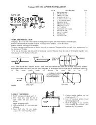
STRAP-ON SENSORSThe strap-on sensors for the Series <strong>4500</strong> are designedfor external mounting on pipes made of material, such assteel or plastics, that will support ultrasonic signaltransmissions. The mounting hardware is constructed ofcorrosion resistant materials and designed for ease ofinstallation.It is important that the sensors are installed correctly onthe pipe to ensure good accuracy. A template is providedfor positioning the sensor holders on the pipe. The properconfiguration for your application is indicated on the datasheet in the front of this manual. When properly installed,the sensors will be located 180 degrees apart on oppositesides of the pipe and be offset upstream and downstreamby the distance on the Data Sheet in the front of thismanual. The sensors may be mounted on horizontal orvertical pipe runs. If the pipe is horizontal, the sensors mustbe located on the sides and not on the top and bottom.It is important that there be as much upstream straightrun as possible so there will be a well developed velocityprofile at the point of measurement. There should be 3pipe diameters of downstream straight run after the pointof measurement.WIDTHMOUNTING CONFIGURATION7" Case B & C14" Case D21" Case E28" Case F35" Case G42" Case H49" Case I56" Case J3-2
SERIES 4000 V-SHOT INSTALLATIONITEM DESCRIPTION QTY1.2. 3.5.4.6.1. SENSOR HOLDER 304 S/S 12. SENSOR W/100 FT. CABLE 23. SENSOR CLAMP & 7/16 HEX HEAD SCREW 44. SILICONE (FOR SENSORS) 15. WIRE ROPE 1/8" DIA. (CUT PER ORDER) 26. ALLEN WRENCH 1NOTE: Pipe preparation before installation. It may be necessary, particularly with Cast Iron or Ductile Ironpipe, to sand pipe to a smooth and radial surface where the sensors are to be placed.Place the probe holder (1) on the top of the pipe.43289710PIPE165WRAPPING THE CABLE1. Place one end of the stainless steel cable through the slot closet tothe rail and opposite of the clamp side.2. Pull cable over the groove in the tension holder (9).3. Pull cable through the slot on the holder.4. Wrap cable completely around the pipe.5. Pull cable through the slot on the holder.6. Pull cable over the groove in the tension holder (9).7. Pull cable through the slot on the holder.8. Loosen the cable clamp with the socket head screw. Slide thecable between the probe holder and the cable clamp. Pull theexcess cable through the clamp.9. Tighten the socket head screw.Repeat the above instructions for the other end of the probe holderand cable.Slide the probe holder down to the side of the pipe.10. Use the Allen wrench and turn the tension holder screw (10)counterclockwise until the probe holder is tight against the pipe.Place a single bead of silicone grease (4) longitudinally along the PVC face of the sensor. Slide sensor (2) into sensorholder (1), note that the sensor cable (yellow) will be pointing toward the other sensor (Fig. 3). Use sensor clamp (3) andplace the top over the sensor with knobs in sensor hole and place the bottom of the clamp on the bottom of the rail of thesensor holder. (See A-A detail)3.A-A1.3.SENSOR SEPARATIONIN INCHES*** (Inside edges of sensors)***2.1232.1.5431SILICONE GREASE (4.) A-A DETAIL3. FIG. 2FIG. 3See Data Sheet in front of customer <strong>IOM</strong> manual. Locate on Page 2 of Data Sheet Sensor Style Section. The SensorOffset in inches will be displayed as “Offset #.### Inches”. The offset in inches is the separation to be used on the topruler on the probe holder. Align Top right edge of the left hand sensor on the “0” on the top ruler on the sensor holder.Move the right hand sensor to the sensor separation in inches using the upper left edge of the right hand sensor to theOffset distance. Tighten hex head screws on the sensor clamp (3) snugly to the sensor holder with Hex wrench. See <strong>IOM</strong>manual for cable termination at electronics.3-3
SERIES 4000 Z STRAP-ON SENSOR INSTALLATION (CASE B)ITEM DESCRIPTION QTY1.2. 3.5.4.6.7.1. SENSOR HOLDER 304 S/S 22. SENSOR W/100 FT. CABLE 23. SENSOR CLAMP & 7/16 HEX HEAD SCREW 44. SILICONE (FOR SENSORS) 15. WIRE ROPE 1/8" DIA. (CUT PER ORDER) 46. ALLEN WRENCH 17. MYLAR TEMPLATE 1NOTE: Pipe preparation before installation. It may be necessary, particularly with Cast Iron or Ductile Iron pipe, tosand pipe to a smooth and radial surface where the sensors are to be placed. If pipe is Asbestos Cement place a coat ofshellac over the surface where the sensors are to be mounted.Using tape, attach one end of the template (7) to the pipe and wrap the rest of the template around the pipe. Pull thetemplate straight and mark the point of overlap on the template. Cut off the excess.CUTCREA SERemove template from pipe. Fold template exactly in half and crease in the middle. Wrap the template around the pipeso that the crease is on one side of the pipe and the two ends of the template meet on the other side of the pipe. Try toline up the crease and ends with the horizontal center of the pipe. Tape the ends of the template together with maskingtape to hold in place on the pipe (Fig. 1).LEFT BLACK LINERIGHT BLACK LINEHOLDERHOLDERTEMPLATEENDSCREASEFig. 1 Fig. 2Fig. 3Place the probe holders (1) on the top of the pipe. The probe holder on the right hand side should have the ruler on theupper right corner and should be lined up with the right black line in the middle of the template (Fig. 2 & 3). The probeholder on the left should be upside down and have the ruler on the lower left corner and should be lined up with the leftblack line in the middle of the template (Fig. 2 & 3).43289710PIPE165WRAPPING THE CABLE1. Place one end of the stainless steel cable through the slot closestto the rail and opposite of the clamp side.2. Pull cable over the groove in the tension holder (9).3. Pull cable through the slot on the holder.4. Wrap cable completely around the pipe.5. Pull cable through the slot on the holder.6. Pull cable over the groove in the tension holder (9).7. Pull cable through the slot on the holder.8. Loosen the cable clamp with the socket head screw. Slide thecable between the probe holder and the cable clamp. Pull theexcess cable through the clamp.9. Tighten the socket head screw.Repeat the above instructions for the other end of the probe holderand cable.Slide the probe holder down to the side of the pipe. Align the centeron the holder to the template fold and the ends.10. Use the Allen wrench and turn the tension holder screw (10)counterclockwise until the probe holder is tight against the pipe.3-4
Place a single bead of silicone grease (4) longitudinally along the PVC face of the sensor. Slide sensor (2) into sensorholder (1), note that the sensor cable (yellow) will be pointing toward the other sensor (Fig. 4). Use sensor clamp (3) andplace the top over the sensor with nubs in sensor hole and place the bottom of the clamp on the bottom of the rail of thesensor holder. (See A-A detail)3.A-A2. 1.1.3.SENSOR SEPARATIONIN INCHES******2.0213SILICONE GREASE 4.A-A DETAILFIG. 4 FIG. 5See Data Sheet in front of customer <strong>IOM</strong> manual. Locate on Page 2 of Data Sheet Sensor Style Section. The SensorOffset in inches will be displayed as “Case-B Offset #.### Inches”. The offset in inches is the separation toe used on thetop ruler on the probe holder. Align right edges of the sensors on the “0” on the rulers on both sensor holders. Eithermove one sensor to the sensor offset using the right edge of the sensor, or divide Offset by 2 and move both sensors 1/2the Offset distance. Tighten screw on the sensor clamp (3) with the wrench. See <strong>IOM</strong> manual for cable termination atelectronics.UPSTREAM SENSORFig. 8NOTE: DIRECTIONOF SENSOR CABLEPUT A BEAD OF SILICONEGREASE DOWN THE MIDDLEOF EACH SENSORTEMPLATE0213FLOWCUT OUT THE TEMPLATEMATERIAL FROM INSIDE THE HOLDERDOWNSTEAM SENSOR3-5
SERIES 4000 Z STRAP-ON SENSOR INSTALLATION (CASE C THRU J)ITEM DESCRIPTION QTY1.2. 3.5.4.6.7.1. SENSOR HOLDER 304 S/S 22. SENSOR W/100 FT. CABLE 23. SENSOR CLAMP & 7/16 HEX HEAD SCREW 44. SILICONE (FOR SENSORS) 15. WIRE ROPE 1/8" DIA. (CUT PER ORDER) 46. ALLEN WRENCH 17. MYLAR TEMPLATE 1NOTE: Pipe preparation before installation. It may be necessary, particularly with Cast Iron or Ductile Iron pipe, tosand pipe to a smooth and radial surface where the sensors are to be placed. If pipe is Asbestos Cement place a coat ofshellac over the surface where the sensors are to be mounted.Using tape, attach one end of the template (7) to the pipe and wrap the rest of the template around the pipe. Pull thetemplate straight and mark the point of overlap on the template. Cut off the excess.CUTCREA SERemove the template from pipe. Fold template exactly in half and crease in the middle. Wrap the template around thepipe so that the crease is on one side of the pipe and the two ends of the template meet on the other side of the pipe. Tryto line up the crease and ends with the horizontal center of the pipe. Tape the ends of the template together with maskingtape to hold in place on the pipe (Fig. 1).LEFT EDGERIGHT EDGEHOLDERHOLDERTEMPLATEENDSCREASEFig. 1 Fig. 2Fig. 3Place the probe holders (1) on the top of the pipe. The probe holder on the right hand side should have the ruler on theupper right corner and should be lined up with the right edge of the template (Fig. 2 and 3). The probe holder on the leftshould be upside down and have the ruler on the lower left corner and should be lined up with the left edge of thetemplate (Fig. 2 & 3).WRAPPING THE CABLE1. Place one end of the stainless steel cable through the slot closest to2the rail and opposite of the clamp side.10 12. Pull cable over the groove in the tension holder (9).53. Pull cable through the slot on the holder.4. Wrap cable completely around the pipe.3695. Pull cable through the slot on e holder.6. Pull cable over the groove in the tension holder (9).77. Pull cable through the slot on the holder.8. Loosen the cable clamp with the socket head screw. Slide the cablebetween the probe holder and the cable clamp. Pull the excesscable through the clamp.89. Tighten the sock head screw.PIPERepeat the above instructions for the other end of the probe holder andcable.4Slide the probe holder down to the side of the pipe. Align the centerof the holder to the template fold and the ends.10. Use the Allen wrench and turn the tension holder screw (10)counterclockwise until the probe holder is tight against the pipe.3-6
Place a single bead of silicone grease (4) longitudinally along the PVC face of the sensor. Slide sensor (2) into sensorholder (1), note that the sensor cable (yellow) will be pointing toward the other sensor (Fig. 4). Use sensor clamp (3) andplace the top over the sensor with nubs in sensor holes and place the bottom of the clamp on the bottom of the rail of thesensor holder. (See A-A detail)3.A-A2. 1.1.3.2.SENSOR SEPARATIONIN INCHES***0213***SILICONE GREASE 4.A-A DETAILFIG. 4 FIG. 5See Data Sheet in front of customer <strong>IOM</strong> manual. Locate on Page 2 of Data Sheet Sensor Style Section. The SensorOffset in inches will be displayed as “Case C-J Offset ##.### Inches”. The offset in inches is the separation to be usedon the rulers on the probe holders. Align the right edges of sensors on the “0” on the rulers on both sensor holders.Either move one sensor to the sensor offset using the right edge of the sensor, or divide Offset by 2 and move bothsensors 1/2 the Offset distance. Tighten screw on sensor clamp (3) with wrench. See <strong>IOM</strong> manual for cable terminationat electronics.UPSTREAM SENSORNOTE: DIRECTIONOF SENSOR CABLEPUT A BEAD OF SILICONEGREASE DOWN THE MIDDLEOF EACH SENSORTEMPLATE0213FLOWCUT OUT THE TEMPLATEMATERIAL FROM INSIDE THE HOLDERDOWNSTEAM SENSOR3-7
SERIES 4000 2 INCH SENSOR INSTALLATION1. 2.ITEM DESCRIPTION QTY1. SENSOR 2" 12. U BOLT 23. WRENCH 7/16 X 1/2 14. SPRING 45. FLAT WASHER 46. NUT HEX 1/2-13 S/S 47. SILICONE (FOR SENSORS) 1345. 6. 7.NOTE: Pipe preparation before installation. It may be necessary to sand pipe to a smooth and radial surface where the sensorsare to be placed.Place a single bead of silicon grease (7) longitudinally along the PVC face of the sensor. Locate the flow direction arrowon the sensor plate. Place sensor (1) onto the side of the pipe with the flow direction arrow pointing with the forwardflow direction. Put one U-bolt (2) around the pipe through the holes on the sensor plate (Fig. 1). Place a flat washer (5),spring (4), and flat washer (5) over the two threaded ends of the U-bolt. Screw the nut (6) down snugly to the top flatwasher. Place the other U-bolt around the pipe and through the other end of the sensor. Place washers, spring and nut asabove.FLOWFLOW7.FIG. 16.5.4.5.4 PLACES1.2.UPSTREAM SENSOR TAGTape the end of the upstream sensor cable before running both cables through conduit. This will ease the termination ofthe cables at the electronics enclosure. The taped end is the upstream connection and the untaped end is the downstreamconnection. Tighten nuts (6) to compress the springs to approximately 0.75 inches with the wrench (3). See <strong>IOM</strong> manualfor cable termination at electronics.3-8
SERIES 4000 HI TEMP SENSOR INSTALLATIONNOTE: FOLLOW SENSOR INSTALLATION INSTRUCTIONS FOR STYLE OF STRAP-ON SENSORSINDICATED ON DATA SHEET.JUNCTION BOXUPSTREAM SENSORPUT A BEAD OF SILICONEGREASE DOWN THE MIDDLEOF EACH SENSORBadgerMFLOW022 3DOWNSTEAM SENSORHI TEMP JUNCTION BOXWITH PCB CONNECTION BOARDTO ELECTRONICSENCLOSUREJ1J2TO SENSORSJ3J4JUNCTION BOX WIRINGJ1 TO HI TEMP SENSORJ3 TO HI TEMP SENSORJ2 TO 100FT CABLE/ELECTRONICSJ4 TO 100FT CABLE/ELECTRONICS1. Place junction box on the top of the pipe orienting the two conduit hole side towards the mounted sensors.2. Wrap stainless steel strap around the underneath side of the pipe and run each end through the snap lock screw oneach end of the straps on the junction box. Lock one end of the snaplock onto the strap and pull the other end astight as possible through the other snaplock before snapping onto the strap. Use a flat head screw driver and tightenthe screw on the snap lock. This will tighten the strap around the pipe.3. Place the conduit fittings from the flexible conduit from the sensors into the two holes provided in the junction box.Tighten the nuts onto the conduit fittings.4. The BNC connectors from the sensors will be connected to the BNC connectors of J1 and J3 connections.5. The customer supplied conduit should be installed in the one hole side of the junction box.6. The BNC connectors are factory installed on two 100 ft. cables. The BNC connectors from the triax cables shouldbe connected to J2 and J4 connections.7. Mark the end of one cable with a piece of tape designating either the upstream or the downstream sensor.8. Terminate the sensor cables per wiring in the <strong>4500</strong> <strong>IOM</strong> manual.3-9
SERIES 4000 WINDOWED SPOOL INSTALLATION1. SPOOL2. ROLL PIN (USED AS A GUIDE FOR #4)3. O RING4. SENSOR WINDOW5. SENSOR HOLDERFIG.16. WASHER (4 PLACES)7. SCREW (4 PLACES)8. SILICONE GREASE9. RUBBER PAD10. SENSOR & CABLE11. SPRINGCaution12. CAUTION TAG13. SENSOR RETAINER1 2 3 4 5 6 7 8 9 8 10 11 12 13WARNING:DO NOT REMOVE ASSEMBLY #3 THROUGH #7FLOWLIFTING LUGS TO TOP OF PIPEINSTALL WITH ARROW POINTING WITH FLOWSPOOL PIECES MAY BE INSTALLED EITHER IN THE HORIZONTAL PLANE OR IN THEVERTICAL PLANE (WITH FLOW IN THE UP DIRECTION)L = LAYING LENGTH IN INCHESI.D.SIZE 3 4 6 8 10 12 14 16 18 20 24 30 36 42 48"L" 12 12 12 14 15 18 21 24 27 30 36 30 36 42 48LAWWA CL. D125# FFANSI 150# RFPLAIN ENSENSOR REMOVAL PROCEDURE1. Remove conduit from the sensor retainer (12).2. Unscrew the sensor retainer (12).3. Gently pull on the sensor cable. The sensor spring (10) and the sensor (9), should "pop" out of the sensor holder (5).4. Before reinstalling the sensor, carefully clean the sensor grease from the sensor window lens (4).NOTE: A long 6" cotton swab available at most electronic, or audio, stores works well for cleaning the window.5. Wipe the end and sides of the sensor clean, removing any grease and grit.6. Spread a thin 1/32" layer of sensor grease (Dow Corning 111* valve lubricant & sealant) on the end surface of the sensor.7. Carefully reinsert the sensor into the sensor holder and gently push the sensor all the way in.NOTE: If the sensor will not push in, try to loosen the holder screws (7) slightly (without removing the safety wireseal) and shift the holder until the sensor will slide all the way in. Retighten the holder screws.8. Screw the sensor retainer down firm (hand tight) and reconnect the conduit.* Type 29 silicon heat sink compound may be used (available at most electronic stores).3-10
SERIES 4000 HS3 SENSOR INSTALLATIONPARTS LIST2 1 3 4 5 6 7 8 9 101511 12 13 14ITEM DESCRIPTION QTY1. RETAINER BRZ 22. SPLIT COLLAR 23. BRASS COLLAR 24. O-RING 1.287 X 2.7 25. O-RING 2.112 X 2.318 26. 2" RETAINING RING 27. BEARING SEAL 28. BRASS TAIL PIECE 29. BRZ BALL VALVE 210. 1-1/2" NIPPLE 211. SENSOR W/100' CABLE 212. SAFETY PLATE 413. SAFETY CABLE 414. TEMPLATE 115. TEFLON TAPE 1TEMPLATE INSTALLATIONUsing tape, attach one end of the template to the pipe and wrap the rest of the template around the pipe.Pull the template straight and mark the point of overlap on the template. Cut off the excess.Remove template from pipe. Fold template.Wrap the template around the pipe so that the crease is on one side of the pipe and the two ends of the template meet onthe other side of the pipe.Try to line up the crease and ends with the horizontal center of the pipe. Tape the ends of the template together withmasking tape to hold in place on the pipe.3.CUT1.CREASE2.TEMPLATEENDSCREASEUse a center punch and a hammer. Punch a mark where the template ends meet and the right edge of the template.Repeat step on the other side of the pipe where the crease in the template and the right edge of the template meet (Fig.4). The center punch marks will become the center line for the 1-1/2" nipples.4.1-1/2" FEMALE NIPPLES(TAPPING SADDLESOR THREADOLETS)FLOWSIDE VIEWTOP VIEW9TAPPING PROCEDURE1. Install template and nipples per 3-1.2. Use Teflon tape, wrap the end ofmale nipple (10 and screw intofemalenipple of tapping saddle.3. Slide safety plate (12) over outer endof nipple.4. Screw ball valve (9) onto nipple.Adjust valve to the "open" position.FLOW10121-1/2" SADDLE NIPPLE5. Connect tapping machine into endof ball valve, 1-1/2".6. Use 1.38" minimum tapping bit andtap through pipe wall.7. Back the tapping bit out past thevalve assembly and move the valvehandle to the "off" position.3-11
PREPARATION TO INSTALL SENSORS:SERIES 4000 HS3 SENSOR INSTALLATIONFIG. 1 FIG. 2SEE NOTE 1 PG. 3-35 6 7815NOTE SCRIBEMARKTAIL PIECE ASSEMBLY(ASSEMBLED AT FACTORY)11 12 1 2 3 4SENSOR & COLLAR ASSEMBLY11 12 1 2 3 4 5 6 7 8 9 12 10FIG. 38.15""S""S"= Length of saddle or threadolet nipple"T"= Length from i.d. of pipe to outsideedge of item 8"T" MEASURED BY INSTALLER"T"+0.82" OR 8.97"+"S"+WALL THICKNESSNOTE 1:USE ABOVE FORMULAS TO DETERMINE THE PLACEMENT OF ITEM 2, ONCE COLLAR ISPLACED AT CORRECT DIMENSION TIGHTEN BOTH SOCKET HEAD SCREWS.1. Screw tail piece assembly (Fig. 1, 5, 6, 7 and 8) into ball valve (9).2. Slide 12 and 1 onto sensor (11); use Fig. 2.3. Position collar (2) onto sensor and use above formula to calculate correct dimension. Please note that the collarshould already be installed by the factory on new orders, the collar dimension will have to be changed only if pipedimensions are other than given.4. Slide brass collar and O-ring assembly (3 & 4) onto end of sensor and butt up against the split collar (2).NOTE: USE SOAPY WATER, PETROLEUM JELLY OR SOME TYPE OF LUBRICANT TO SLIDE BRASSCOLLAR AND O-RING ONTO SENSOR.5. Note scribe mark running near the end of the sensor. This scribe mark, when the sensor is installed, should be facingtoward the opposite sensor (Fig. 4).6. Place tip of sensor through bearing seal (7) and carefully push until the sensor stops at the ball valve. Fasten safetycable clip (long length) to opposite safety plate.7. Turn valve handle to the "on" position and insert the sensor until the brass collar (3) seats on the O-ring on the tailpiece (5 & 8).8. Tighten retainer (1) onto the tail piece (8) using a 1/16" square screw driver shaft in the notch on the end of theretainer.9. Fasten short length of safety cable to opposite safety plate.3-12
SERIES 4000 HS3 SENSOR INSTALLATIONUPSTREAM SENSORSCRIBE MARKFLOWNOTE: TIPS OF SENSORS WILLBE FACING EACH OTHERFIG. 4SCRIBE MARKDOWNSTREAM SENSORSYSTEM DIAGRAMJUNCTION BOX(CUSTOMER SUPPLIED)METALLIC CONDUIT(CUSTOMER SUPPLIED)117/230VACOR 12VDCOUTPUTSFLEX CONDUIT(CUSTOMER SUPPLIED)3-13
SERIES 4000 INSTREAM REFRACTING SENSOR INSTALLATIONDESCRIPTIONThe instream refracting sensors were designed for rectangularor circular concrete channels flowing full at all times. Thesesensors have a wedge shape to minimize possibilities ofcatching debris. The sensor is made of PVC materials with 50ft. of Belden triax cable.INSTALLATIONRefer to customer Data Sheet in front of this manual. Sensorseparation = ____.____ inches. This dimension is from centerline of the upstream sensor to the center line of thedownstream sensor. Make sure that the arrow on thedownstream sensor is pointing upstream and the arrow on theupstream sensor is pointing downstream. Mark holes onconcrete conduit and use lead inserts. Place sensor over leadinserts and attach with screws (customer supplied). Route thesensor cables to the top of the conduit and use customersupplied cable clamps to fasten cable to the pipe at one footintervals. Route the cables downstream and out the pipeoutlet. Secure with cable clamps.Terminate sensor cables to the <strong>4500</strong> electronics.2.03/8" HOLES1.758.56.515/16" COUNTER BORE SENSOR CABLE20°TOPNOTE: ARROWS ON TOP OF SENSORSSHOULD BE POINTING TOWARDSEACH OTHER AFTER INSTALLATIONUPSTREAM SENSORFLOW***DOWNSTREAM SENSOR***SENSOR SEPARATION(THIS DIMENSION IS CRITICALTO METER ACCURACY)3/4" METALLIC CONDUITJ-BOX(CUSTOMER SUPPLIED)CABLECLAMPS180°**** 2-5 pipe dia.3-14
SERIES 4000 WETTED SENSORS WITH HOOP INSTALLATIONDESCRIPTIONThe underwater sensors for the Series <strong>4500</strong> flow meterare premounted on a stainless steel plate at the factory(see Fig. 2). The sensor cables are secured to the platewith clamps. This plate is then formed into a hoop andinserted into the pipe just upstream of the 2-inch conduitopening in the top of the pipe or upstream of the manholeentrance. The sensor cables are then pulled through theconduit and attached to the sensor connections on theModel <strong>4500</strong> electronic enclosure.PROCEDURE1. Inspect the sensor mounting plate for evidence ofdamage from shipping or handling.2. Refer to Fig. 1. Form the plate into a hoop. Insert thefour 8-32 studs on one end of the plate into the slotson the other end. Loosely attach the holding strap tothe four studs with the flat washer, Bellville washerand nut. Compress the hoop to its smallest diameterand tighten the nuts on the holding strap.3. Lower the sensor mounting assembly into thedischarge box at the end of the pipe, positioning it sothe sensor cables exit downstream. Insert it into thepipe 3 inches upstream of the 2 inch conduit pipeopening in the top of the pipe or 2 to 5 pipe diametersupstream of the manhole. Position the hoop so thesensors are at 90 and 270 degrees in the pipe.4. Loosen the nuts to the holding strap. Expand thehoop to the wall of the pipe and loosely tighten theunits on the holding strap.5. Use large "C" ring pliers to secure the mounting plateto the pipe. Starting at the upstream side of themounting plate, place the "C" ring pliers between thesecond slot and the holding strap. Slowly spread themounting plate with the pliers forcing the mountingplate against the pipe. Using a rubber head mallet, tapthe plate starting at the bottom and up the sides.Tighten the nut of the holding strap on the end youhave been spreading. Place the "C" ring pliers on thedownstream side of the plate and repeat the sameprocess. Go back to the upstream end and loosen theend nut and use the "C" ring pliers to continue toforce the plate against the pipe wall. Repeat thisprocess until the mounting plate is secured againstthe pipe wall and there are no gaps between the plateand wall.6. Refer to Fig. 3. Route the sensor cables downstreamto exit.7. This completes the sensor installation. See theelectronic assembly installation section forconnecting and securing the cables.HOLDING STRAPFLAT WASHERBELLVILLE WASHERNUTFIG. 1SENSOR MOUNTING PLATE3-15
SERIES 4000 WETTED SENSORS WITH HOOP INSTALLATIONSENSOR MOUNTINGPLATEHOLDING STRAPSENSORSFIG. 2CABLE CLAMP3/4" METALLIC CONDUITCUSTOMER SUPPLIEDJ-BOXCUSTOMER SUPPLIEDCABLE(1000 FT MAX)CABLE CLAMPS(1 FOOT INTERVALS)FLOWFIG.3**** 2-5 PIPE DIAMETERS3-16
OPERATIONBadger MeterCompu-SonicFLOW 1234 GPM X 10 OKTOTAL 123456 GAL X 10MODEL <strong>4500</strong>GENERAL DESCRIPTIONThe Series <strong>4500</strong> is an ultrasonic transit-time flow meterdesigned to measure fluid flows in full pipes. The meter isequipped with a 2-line, 24 character per like LCD display,4-20 mADC signal output, 4 programmable relays and anRS232 serial communications port.The Series <strong>4500</strong> is microprocessor based and providesa number of menu functions from the front panel whichallows the user to modify or interrogate meter operationsto suit the user's needs. These keys are the UP arrow,DOWN arrow, RIGHT arrow, MENU and ENTER.The MENU key allows access to the Status Mode orCalibration Mode of the meter. It also can be used to returnto normal operation any time you are in the Status orCalibration Mode. If you press the MENU key while in theCalibration Mode, the processor will store any changesmade up to that point, but will retain the previousprogramming after that point and return to the normaloperating screen.The ENTER key is used to store any data changes that aremade in the Calibration Mode and step through the screensof the Status or Calibration Modes. The ENTER key mustbe pressed to store the change made. Pressing the MENUkey before the ENTER key will not store the change.The UP, DOWN, and RIGHT arrow keys are used forselecting or making changes in the various screens of themeter in the Status or Calibration Mode.To prevent unauthorized entry into me Calibration Modeof the meter, there is a Security screen that requires thecorrect security code to be entered in order to gain access.The security code when shipped from the factory is 0000.When power is first applied, the display will show squaresacross the top line for a second and then the display willshow the normal operating screen, typically flow and total.The flow rate value will have 3 X's for 3 to 5 seconds whilethe meter is going through its set up procedure. The meterwill then begin to indicate the flow rate if an OK isdisplayed in the right corner of the top line as shown below.FLOW 3480 GPM X 10 OKTOTAL 458932 GAL X 1000If you meter has been programmed at the factory for bidirectionalflow, there will be a letter that follows theFLOW word and a letter at the right end of the secondline that will indicate the direction of the flow. The letterwill be F for forward flow and R for reverse flow. Thescreen below shows this feature.FLOW F 3480 GPM X 10 OKTOTAL 458932 GAL X 1000 FThere are two totalizer registers in the meter. One forforward flow and the other for reverse flow. While in thenormal operating screen, the UP or DOWN arrow keyscan be used to view the totalizer that is not displayed.The following pages in this section cover the Status andCalibration Modes' menus. They will be listed in the orderof the sequence of screens.The MENU key can be used to exit from any functionin the Status or Calibration Modes and go directly back tothe normal operating screen. The DOWN arrow key canbe used to step backwards in the main function screens.4-1
STATUS MODEThe Status Mode allows the user to determine theoperational status of the Series <strong>4500</strong> as well as perform aself diagnostic and a flow simulation. Normal meteroperation will still be performed while in the Status Modeexcept when in the flow simulation function.To enter into the Status Mode, press the MENU keyand the following screen will appear:PRESS UP FOR CALIBRATIONPRESS DOWN FOR STATUSThis screen allows entry into the Calibration Mode orthe Status Mode. Press the DOWN arrow key and thefollowing screen will appear:Measurement DataPress UP to ActivateThis screen allows entry into the measurement data ofthe meter. This is normally used in troubleshooting todetect signal strength and error codes.Press the UP arrow key and the following screen willappear:ZOF = 0000DEL = A9C2NOR = BE38T12 = 02C4This screen of the measurement data gives the values ofthe captured zero offset (ZOF),a the normalized flow rate(NOR), the phase shift (DEL) and the signal crossingtime (T12). These will be discussed in more detail in theTroubleshooting Section of this manual.Press the ENTER key and the following screen will appear:ERR 0000SIG:AGC = 25024FThis screen shows the error codes and the AGC(automatic gain control) value on the first line and thesignal strength indication on the second line.The various error codes are listed in theTroubleshooting Section of this manual. The first twohexadecimal digits of the AGC value indicate the relativestrength of the received signal with a value of 9F for aminimum signal and 10 the maximum signal.You may switch between the two screens by pressingthe UP arrow key.Press the ENTER key and the following screen will appear:SELF TESTPRESS UP TO ACTIVATEThis screen allows entry into the self test diagnosticsroutine. Press the UP arrow key and the following screenwill appear:SELF TESTTRANSMIT: The self diagnostic first tests the transmitter section ofthe electronics. A brief message will be displayedindicating that testing is in process and then a PASSED orFAILED message will appear. The self test automaticallysteps through each test segment.The following screen will appear next:SELF TESTRECEIVER: Again a brief message will be displayed indicating thattesting is in process and then a PASSED or FAILEDmessage will appear. This test checks that the receiversection of the electronics is functioning properly. The selftest then checks for the presence of a signal. If a receivedsignal is present and within the timing limits, the self testwill step to the EEPROM test. If there is no signal, thiswill be indicated on the display. If there is a signalarriving at a time shorter than expected, then 'T12 Short'will be displayed. If there is a signal arriving at a timelonger than expected, then 'T12 Long' will be displayed.The following screen will appear next:SELF TESTEEPROM: This screen indicates that the EEPROM of themicroprocessor is being tested. After a few seconds the"TESTING" message will change to either "PASSED" or"FAILED". The following screen will appear:SELF TEST*****Completed*****This screen indicates that the self test function of the StatusMode is completed. The following screen will appear:<strong>Flow</strong> SimulationPress UP to ActivateThis screen allows the entry into the flow simulationfunction. This function can be used to simulate the flow fromzero to full scale. It will drive the 4-20 mADC output and therelays if assigned to either of the flow set points.4-2
When in this function the normal flow measurement of themeter is discontinued. No totalization of flow will take place,but any totalization in <strong>Flow</strong> Simulation will record on thenormal totalizer.Press the UP arrow key and the following screen will appear:FLOW 0000 GPM X 10 SMBadger Meter, Inc.This screen is the flow simulation screen. In the top, rightcorner of the display are the letters SM. These letters are toprevent confusion with the normal flow screen. The meter willstay in this mode until the MENU key is pressed.To adjust the flow simulation to a specific flow rate,use the RIGHT arrow key to move the cursor under thedigit to be adjusted and use the UP or DOWN arrow keysto adjust the digit to the desired value. For example, ifyou wanted to simulate a flow rate of 2500 GPM, movethe cursor under the second digit from the left with theRIGHT arrow key and press the UP arrow key twice for avalue of two (2). Then move the cursor under the thirddigit from the left with the RIGHT arrow key and pressthe UP arrow key five times for a value of five (5). Thedisplay will now show 0250 which is 2500 GPM with theX10 multiplier.To exit from the flow simulation press the MENU key.The screen will return to the normal operating screen.To exit from any screen and go back directly to thenormal operating screen, press the MENU key.This completes the Status Mode operation instructions.CALIBRATION MODEThe Calibration Mode allows the user to calibrate andadjust various functions related to the operation of theSeries <strong>4500</strong>. A brief description of each follows.4-20 mA Calibration - Adjusts the zero and span(4-20 mA) output.Meter Rescale - Changes the full scale range of themeter.Meter Factor - Adjusts meter factor for field calibration.Zero Offset - Performs zero offset capture at no flowcondition.Totalizer - Enables or disables totalizer or clearstotalizer.Response Time - Adjusts the response time of the meter.Failure Mode - Selects default output of meter when lossof signal occurs.Integrator Configuration - Sets contact output inmultiplies of the totalizer multiplier.Remote Tot Configuration - Sets closure time of relayfor remote totalizer.Set Point Configuration - Adjusts two set points for highor low flow alarms.Relay Configuration - Assigns alarms or set points to thefour relays.Security ID - Changes the security code.To enter into the Calibration Mode, press the MENUkey while the display is in the normal operating screen.The following screen will appear:PRESS UP FOR CALIBRATIONPRESS DOWN FOR STATUSPress the UP arrow key and the following screen willappear:SECURITY IDInput 4 Digit Id - - - -This screen is the Security screen which requires thecorrect 4 digit number to allow entry into the CalibrationMode of the Model <strong>4500</strong>. To change the value of eachdigit, move the line under the digit to be changed with theRIGHT arrow key and then use the UP or DOWN arrowkeys to change the value of the digit. When the 4 digitnumber is correct, press the ENTER key. If the number isincorrect the meter will go back to the normal operatingscreen. If the number is correct the following screen willappear:4-20 mA CalibrationPress UP to ActivateThis screen allows entry into the Calibration screens forthe 4-20 mA current output. Press the UP arrow key andthe following screen will appear:4-20 mA CalibrationZERO WORD = 23004-3
This screen allows adjustment of the zero output to 4mA. The 4-20 mA output can be monitored on the testjacks on the bottom of the back half of the housing, redjack positive, black jack negative. The 4-20 mA outputmust be connected to a load for the test points to work. Use theRIGHT arrow key to position the cursor under the digit tobe adjusted. Fine adjustment is made on the far right digitwith the adjustment becoming more coarse with eachdigit to the left. Use the UP or DOWN arrow keys toadjust for the correct output. The display Zero Word isfor reference only. Press the ENTER key to store thevalue. The following screen will appear:4-20 mA CalibrationSPAN WORD = AD00This screen allows adjustment of span to 20 mA. The4-20 mA output can be monitored on the test jacks on thebottom of the back half of the housing. Use the RIGHTarrow key to position the cursor under the digit to beadjusted. Fine adjustment is made on the far right digitwith the adjustment becoming more coarse with eachdigit to the left. Use the UP or DOWN arrow keys toadjust for the correct output. The display Span Word isfor reference only. Press the ENTER key to store thevalue. The following screen will then appear:Meter RescalePress UP to ActivateThis screen allows entry into the meter rescale screenwhich increases or decreases the full scale of the meter.Press the UP arrow key and the following screen willappear:Meter RescaleFull Scale 0900 x 10The full scale value shown on this screen is the presentfull scale (20 mA output). To change the full scale of themeter, use the RIGHT arrow key to move the cursorunder the digit to be adjusted and use the UP or DOWNarrow keys to adjust the digit to the desired value. Forexample, if you wanted to change the full scale from 9000to 10000, move the cursor under the first digit from theleft with the RIGHT arrow key and press the UP arrowkey once for a value of one (1). Then move the cursorunder the second digit from the left with the RIGHTarrow key and press the DOWN arrow key nine times fora value of zero (0). The display will now show 1000which is 10000 with the X10 multiplier.There is a maximum and minimum full scale limit.When the full scale value reaches either limit, the digitswill stop changing.Remember: Changing the full scale of the meter will causethe 4-20 mADC output to change to reflect the new full scalevalue.Press the ENTER key to store the value. The followingscreen will appear:Meter FactorPress UP to ActivateThis screen allows the user to calibrate the Model <strong>4500</strong>to reproduce actual flow conditions. The user can modifythe meter factor for calibration of the meter to a knownstandard.Press the UP arrow key and the following screen willappear:Meter FactorMeter Factor = 1.000The user can modify the meter factor from a value of0.800 to 1.200. The meter factor is the relation betweenthe indicated flow rate of the meter and the actual flowrate as proven by calibration tanks or other means. If, forexample, the meter was installed on a pipe and due touncertainty in the pipe dimensions, the meter wasdetermined to be indicating a flow rate of 5.6% higherthan the actual flow, the flow meter is indicating 1.056times the true value. The initial meter factor will be 1.000as set as the factory.To correct for the 5.6% high error, the meter factormust be changed to 0.947 (1/1.056). To change the meterfactor, press the RIGHT arrow key to move the cursorunder the first digit to the right of the decimal point andpress the DOWN arrow key to change the value to 9.Press the RIGHT arrow key to move the cursor under thesecond digit to the right of the decimal point and press theUP arrow key to change the value to 4. Press the RIGHTarrow key to move the cursor under the third digit to meright of the decimal point and press the UP arrow key tochange the value to 7. Pressing the MENU or ENTER keywill store the new value.After pressing the ENTER key the following screenwill appear:Zero OffsetPress UP to ActivateThis screen allows the user to capture and correct forzero offsets that may be present in the metering system. It4-4
is intended to be used for periodic maintenance to correctfor small zero drifts. THE FLOW IN THE PIPE MUST BEZERO TO USE THIS FUNCTION. IF FLOW EXISTS INTHE PIPE, USE OF THIS FUNCTION WILL CREATELARGE ERRORS IN THE METER. Therefore, the usermust prepare for use of this function. Appropriate valvingmust be done to ensure that no flow exists; allow at least10 minutes for the fluid motion to settle out. To start theZero Offset function press the UP arrow key and thefollowing screen will appear:Zero OffsetSTAT : Evaluating >The zero offset function is now activated and thedisplay will indicate that it is evaluating for any offsets inthe system. After a period of approximately 20 seconds,the screen will display: 'ERROR: Failed' or"CAPTURED: Press UP to Sav'.If an error is indicated, it means that an offset wasmeasured greater than is expected under normalconditions. The pipe needs to be rechecked to verify thatthere is no flow. Press the ENTER key to step out of theerror screen. The display will step to the TotalizerFunction screen. If you desire to try the zero offsetfunction again, press the DOWN arrow key and thedisplay will step back to the zero offset screen. Repeat theabove procedure.If the screen indicates that an offset is captured, pressthe UP arrow key to store this value. After the UP arrowis pressed the following screen will appear:TotalizerPress UP to ActivateThis screen allows the totalizer to be enabled, disabled,or reset to zero. Press the UP arrow key and the followingscreen will appear:TotalizerENABLEDThis screen allows the totalizer to be enabled ordisabled. If the totalizer is enabled, the totalizer will bedisplayed on the second line of the normal operatingscreen with its appropriate multiplier and units ofmeasurement. If the totalizer is disabled then the secondline of the normal operating screen will have BadgerMeter, Inc. displayed. Use the UP or DOWN arrow keysto make your selection and press the ENTER key.If you selected DISABLED, the next screen displayedwill be the Response Time function. If you selectedENABLED the following screen will appear:TOTALIZER CLEARPress UP to ActivateThis screen allows the user to clear the value in thetotalizer registers of both forward and reverse totalizers ifapplicable. Press the UP arrow and the following screen willappear:TOTALIZER CLEARPress UP to ResetThis screen actually resets the totalizer(s) to zero. Pressthe UP arrow to clear the totalizer(s) or ENTER to notclear the totalizer(s). The following screen will appear:Response TimePress UP to ActivateThis screen allows setting of the response time of themeter to changes in the flow rate. Press the UP arrow keyand the following screen will appear:Response TimeResponse Const: 007This screen sets the response time of the meter. Theselections are from 1 to 7. The response time for each ofthe selections is: 1 = 2 seconds; 2 = 4 seconds; 3 = 8seconds; 4 = 16 seconds; 5 = 32 seconds; 6 = 64 seconds;7 = 128 seconds. Use the UP or DOWN arrow keys tochange to the desired response time. Press the ENTERkey to save. The following screen will appear:Failure ModePress UP to ActivateThis screen allows setting of the default output of themeter in the event there is a loss of signal failure. Thereare three available selections. Zero, Full Scale or HoldLast Reading. The selection of zero will drive the meteroutput to 4 mA. The selection of full scale will drive themeter to 20 mA. The selection of hold last will retain thelast flow value before loss of signal.Press the UP arrow key and the following screen willappear:Failure ModeFAIL TO: ZEROThis screen allows selection of the failure mode to zero,full scale, or hold last reading. Use the UP or DOWNarrow key to make the desired selection. Press theENTER key to store the selection. The following screenwill appear:4-5
Integrator ConfigurationPress UP to ActivateThis screen allows entry into the contact integratorfunction. This feature can be used for activating a sampleror pacing a chemical feed device if assigned to one of therelay outputs. The rate of contact is in multiplies of thetotalizer multiplier. The pulse width or contact time canalso be set for the required time for the external device.Press the UP arrow key and the following screen willappear:Contact Integrator0001 x 1000 GALThis screen allows setting of the contact output basedon specific volume of measured flow. This can beselected on multiples of the totalizer multiplier. Theabove screen shows a totalizer multiplier of 1000 gallons.To have a contact every 10,000 gallons, move the cursorwith the RIGHT arrow key under the third digit from theleft and use the UP arrow key to change it to 1. Move thecursor with the RIGHT arrow key under the last digit anduse the DOWN arrow key to change it to 0.Press the ENTER key to store the new setting and thefollowing screen will appear:Integrator Pulse WidthON FOR 0002 X 0.010 SECThis screen allows setting of the pulse width or contactclosure time for the contact integrator output. Forexample, if the external contact output device is going torequire a closure time of 50 milliseconds, then the on timemust be changed to 0005. That is, 0.050/0.010 = 5. Tochange the on time, use the RIGHT arrow key to movethe cursor under the last digit and the UP arrow key tochange it to 5.Press the ENTER key to store the new setting and thefollowing screen will appear:Remote ConfigurationPress UP to ActivateThis screen allows the entry into the remote totalizerconfiguration setup. If a relay has been assigned to theremote totalizer, then the relay will close every incrementof the display totalizer. The configuration screen sets theclosure time of the relay. Press the UP arrow key and thefollowing screen will appear:Remote Tot Pulse WidthON FOR 0005 X 0.010 SECThis screen allows the setting of the pulse width or contactclosure time for the remote totalizer output. For example, ifthe external totalizer device requires a closure time of atleast 80 milliseconds, then the on time must be changed to0008. That is, 0.080 / 0.010 = 8. To change the on time, usethe RIGHT arrow key to move the cursor under the last digitand the UP arrow key to change it to 8.Press the ENTER key to store the new setting and thefollowing screen will appear:Set Point ConfigurationPress UP to ActivateThis screen allows entry into the configuration screensfor the two set points. The set points can be set up foreither high or low alarms with desired dead band. Pressthe UP arrow key and the following screen will appear:SETPOINT = 01ON AT 00.0% OFF AT 00.0%This screen allows the adjustment of the number 1 setpoint as a high or low alarm as well as the dead band. Fora low alarm, the ON value must be a lower value than the OFFvalue. For a high alarm, the ON value must be a higher valuethan the OFF value. For example, to make the set point ahigh alarm at 90% of full scale flow with a 10% deadband, press the UP arrow key to change the ON value to90.0. The RIGHT arrow key is used to move the cursorunder the digit to be changed. Press the ENTER key tomove the cursor under the OFF digits. Press the UP arrowkey to change the OFF value to 80.0. Press the ENTERkey to store these settings. The following screen willappear:SETPOINT = 02ON AT 00.0% OFF AT 00.0%This screen is for setting the number 2 set point. Usethe same procedure as described for the number 1 setpoint. After pressing the ENTER key to store the settings,the following screen will appear:RELAY CONFIGURATIONPress UP to ActivateThis screen allows entry into the relay configurationscreens where the four relays are assigned to desiredfunctions. Press the UP arrow key and the followingscreen will appear:4-6
RELAY ASSIGNMENTRELAY 01 => NONEThis screen allows the selection of the desiredassignment to the number 1 relay. The followingfunctions are available:NONE - Relay not usedDIR - Direction output for forward and reverse flowTX - Transmitter failure in the electronicsLOS - Loss of signalEEPRM - EEPROM failureTOTL - Remote totalizer outputCINT - Contact integrator outputPNT#1 - Set point #1PNT#2 - Set point #2Use the UP or DOWN arrow keys to make the desiredselection. Press the ENTER key to store the selection.The next screens will be for relays 2, 3 and 4. The sameprocedure is used as for the number 1 relay. After theselection is made for the number 4 relay, the followingscreen will appear:SECURITY IDPress UP to ActivateThis screen allows entry into the Security Identificationwhere the security code may be changed. Press the UParrow key and the following screen will appear:SECURITY IDInput 4 Digit Id 0000This screen will show the present security code in themeter. To change the security code move the cursor withthe RIGHT arrow key under the digit to be changed. Usethe UP or DOWN arrow keys to change the value. Thevalue can be 1 through 9 and A through F. After the newcode has been entered, press the ENTER key to store thenew values. The display will then return to the normaloperating screen.NOTE: At any time after a change has been entered inthe Calibration Mode, the MENU key can be pressed andthe display will return to the normal operating screen.Also the DOWN arrow key can be used to stepbackwards through the main function screens of theCalibration Mode.The following pages diagram the menu screens for theStatus and Calibration Modes.4-7
<strong>4500</strong> STATUS MODEFLOW F 1234 GPM X 10 OKTOTAL 123456 GAL X 100 FMENUMENUPress UP for CalibrationPress Down for StatusMENUMeasurement DataPress UP to ActivateZOF = 0000 NOR = 0000DEL = 0000 T12 = 00C5MENUENTERENTERENTERERR=0000SIG:AGC34A7C2MENUMENUSelf TestPress UP to ActivateSELF TESTTRANSMITR: ENTERSELF TESTRECEIVER: SELF TESTRECEIVER: -NO SIGNAL-SELF TESTEEPROM : ->TESTING
<strong>4500</strong> CALIBRATION MODEFLOW F 1234 GPM X 10 OKTOTAL 123456 GAL X 100 FMENUPress UP for CalibrationPress Down for StatusMENUMENUSECURITY IDInput 4 Digit Id - - - -ENTERMENU4-20 mA CalibrationPress UP to Activate4-20 mA CalibrationZERO WORD = 2300MENUENTERENTERENTER4-20 mA CalibrationSPAN WORD = AB35MENUMENUMeter RescalePress UP to ActivateMeter RescaleFull Scale 3500 x 1MENUENTERENTERMENUMeter FactorPress UP to ActivateMeter FactorMeter Factor = 1.000MENUENTERENTERMENUZero OffsetPress UP to ActivateZero OffsetSTAT : Evaluating >MENUENTERENTERZero OffsetERROR : ** Failed **MENUENTERZero OffsetCAPTURED: Press UP to SavMENU4-9
MENUTotalizerPress UP to ActivateTotalizerENABLEDMENUENTERENTERENABLEDDISABLEDTOTALIZER CLEARPress UP to ActivateMENUENTERTOTALIZER CLEARPress UP to ResetMENUMENUResponse TimePress UP to ActivateResponse TimeResponse Const: 0001MENUENTERENTERMENUFailure ModePress UP to ActivateFailure ModeFAIL TO : ZEROMENUENTERENTERZEROSPANHOLD LASTMENUIntegrator ConfigurationPress UP to ActivateIntegrator Configuration0000 x 1000 GALMENUENTERENTERIntegrator Pulse WidthON FOR 0001 X 0.010 SECMENUENTER4-10
MENURemote Tot ConfigurationPress UP to ActivateRemote Tot Pulse WidthON FOR 0001 X 0.010 SECMENUENTERENTERMENUSet Point ConfigurationPress UP to ActivateSETPOINT = 01ON AT 00.0% OFF AT 00.0%MENUENTERENTERSETPOINT = 01ON AT 00.0% OFF AT 00.0%MENUENTERSETPOINT = 02ON AT 00.0% OFF AT 00.0%MENUENTERSETPOINT = 02ON AT 00.0% OFF AT 00.0%MENUENTERMENURelay ConfigurationPress UP to ActivateRELAY ASSIGNMENTRELAY 01 +> NONEMENUENTERENTERNONEDIRTXLOSEEPRMTOTLCINTPNT#1PNT#24-11
RELAY ASSIGNMENTRELAY 02 => NONEMENUENTERNONEDIRTXLOSEEPRMTOTLCINTPNT#1PNT#2RELAY ASSIGNMENTRELAY 03 => NONEMENUENTERRELAY ASSIGNMENTRELAY 04 => NONEMENUENTERNONEDIRTXLOSEEPRMTOTLCINTPNT#1PNT#2MENUSECURITY IDPress UP to ChangeSECURITY IDInput 4 Digit Id 0000MENUENTER4-12
TROUBLE SHOOTINGGENERALThe Series <strong>4500</strong> is equipped with self test featureswhich allow the user to identify the operation status of theunit and with the help of this section of the <strong>IOM</strong> manualto determine proper action to be taken. This sectiondetails the meaning of the operational codes which appearin the main menu, the meaning of the self test features,and provides a step by step troubleshooting chart fordetermining the fault and the necessary action.Operational Codes. The main menu of the Model <strong>4500</strong>indicates flow rate and flow total. In the upper right handside of the display appears an operational code whichindicates the operating condition of the meter. When themeter is first powered up, the flow rate will displayXXXX and there will not be an operational code. Themicroprocessor is initializing the meter constants andperforming a self test to ensure that all areas of theelectronics are operating properly. This may take severalseconds.After initialization, the X's in the flow rate will changeto 0's. The operational code will display an OK whichindicates the meter is operating properly. The meter mayrecycle a few times before locking onto a good signal.Should an OK not be displayed, refer to thetroubleshooting chart for appropriate action.The following is a list of the operational codes and theirmeanings.OK - Nominal OperationNS - No Signal DetectedXM - Transmit Confirm FailureTL - Signal Transit Time Out of Bounds (too long)TS - Signal Transit Time Out of Bounds (too short)TM - FIFO Error (missing or misaligned timing mark)OF - Amplitude OverflowUF - Amplitude UnderflowGE - Gain ErrorCM - Communications Mode EnabledMeasurement Data Screen in Status Mode: TheMeasurement Data screen of the Status Mode displaysseveralmeasurement parameters that can be used to determinethe operational status of the flow meter. These screens areintended to help facilitate troubleshooting should aproblem exist, especially when communicating with thefactory Service Department. The following is anexplanation of the data:ZOF - Value of the capture zero offset.NOR - Hexadecimal flow rate in percent of full scale.DEL - Hexadecimal measured phase in percent of fullscale.T12 - Hexadecimal measured average transit-time ofthe signals in microseconds.ERR - Error codes.AGC - First two hexadecimal digits represent relativesignal strength with 9F being minimum signalstrength and 10 being maximum signal strength.REPLACEMENT OF PARTSWhile the Series <strong>4500</strong> has been designed and built formaximum reliability, there can be instances wherereplacement of parts may be necessary. In those caseswhere the troubleshooting procedure calls forreplacement of a part, the factory should be contacted forauthorization to send in a defective part for repair orreplacement.The Series <strong>4500</strong> has been designed so that the fronthousing contains the major electronic hardware and canbe easily removed and installed. It also allows thereplacement unit to be preprogrammed with noadjustments required when installing the new unit. Forthis reason, we must know the serial number of thedefective unit when the user contacts the factory forreplacement or repair. Refer to the Installation Section ofthis manual for disassembly instructions.The back housing contains the power supply circuitboard. This replacement will require a little more effort.Refer to Figure 5-1. Disconnect the power wires, sensorcables, 4-20 mADC wires and conduit connections.Remove the two "O" Ring back housing mountingscrews.
BACK HOUSINGPOWER SUPPLY BOARDMAGNETICSWITCHDOTSIGNALWIRESF10.1ATB1HILOGNTB 2TB4UPSTREAMSENSORBAT 4-20MADOWNSTREAMSENSORSW1 SW2 SW3 SW4TP1 +14VDCTP2 GROUNDTP3 +40VDCTP4 +-40VDCTP5 + 4-20 mATP6 Power+45-50VDC4-20 mATest PointsFIGURE 5-1TROUBLESHOOTING CHARTOn the following two pages is the troubleshooting chartfor the Series <strong>4500</strong> flow meter. This chart will help you inisolating possible causes for problems you may encounterand give suggested corrective actions.In the troubleshooting chart, there will be areas thatrequire certain tests to be performed. The followingdescribes these tests.Sensor cable connection continuity test. This test willrequire the use of an ohmmeter. Connect the test leads ofthe ohmmeter to Points 1 and 3 of the sensor cableconnections on the power supply as shown in Figure 5-2.If the signal wires on the power supply board are stillconnected to the front housing electronics, the ohmmeter1234TB2SENSOR CABLE CONNECTIONSON POWER SUPPLY BOARDshould read 5000 ohms +/- 5%. If the signal wires are notconnected, the reading should be 10,000 ohms +/- 5%.Repeat this test at Points 2 and 3.Connect the test leads to Points 3 and 4. The readingshould indicate infinity (or an open).Connect the test leads to Points 1 and 4, then 2 and 4.The reading should indicate infinity (or an open).Power supply voltage test. This test will require the useof a voltmeter. NOTE: With the front housing removed, amagnet will be required to close the magnetic switch onthe back housing in order to perform this test. Refer toFigure 4-1.+14VDC - Connect the test leads to test points 1 and 2on the power supply board. The voltage should read 14VDC +/- 2 volts.+40VDC - Connect the test leads to the test points 2and 3 on the power supply board. The voltage should read40 VDC +/- 1 volt.-40VDC - Connect the test leads to the test points 2 and4 on the power supply board.UPSTREAMSENSORDOWNSTREAMSENSORFIGURE 5-24-20 loop power - Connect the test leads to the test points5 and 6 on the power supply board. The voltage should read45 to 50 VDC when operating the meter on AC power.5-2
TROUBLESHOOTING CHARTSTARTCORRECTPROBLEMREPLACEFUSENONOISDISPLAYON?NOIS115VACPOWER TOUNIT?YESISISTP 1&2FUSEYESCORRECT ONYESOK?POWERSUPPLY?REPLACEELECTRONICSUNITNOISDISPLAYREADABLE?NORECYCLEPOWERCORRECTPROBLEM?NOREPLACEPOWERSUPPLYREPLACEELECTRONICSUNITYESYESERROR CODEON DISPLAY?YESISERRORCODENS?YES GO TOSELF TESTYESTRANSMITPASS?NOREPLACEELECTRONICSUNITNONOCONTINUEDON NEXT PAGEISERRORCODETM?YESCHECK SENSORCONNECTION ORREPLACEELECTRONICUNITISMESSAGENO SIGNAL?YESMAKE SENSORCABLE CONTINUITYTESTNOISERRORCODETL OR TS?YESCHECK SENSORMOUNTINGDIMENSIONSCHECK SENSORMOUNTING &PIPE SURFACESEE MOUNTINGINSTRUCTIONSCORRECTPROBLEM?NOPOSSIBLE AERATIONOR CORRISON ONINSIDE OF PIPEYESAREREADINGSCORRECT?NOCHECK FOR LOOSESIGNAL WIRECONNECTION &BAD CONNECTIONSAT SENSOR CABLECONNECTIONS ORSHORTED WIRES5-3
CONTINUEDDOMENUSWORK?NORECYCLEPOWERCORRECTPROBLEM?NOREPLACEELECTRONICSUNITYESYESIS4-20mAOUTPUTOK?NOISTHEREOUTPUT?YESACTIVATEZERO & SPANMODESAREOUTPUTSCORRECT?NOADJUSTZERO & SPANYESNOYESIS4-20 mATESTPOINTSCORRECT?YESCHECK INSTRUMENTRECEIVING 4-20 mACHECK RECEIVINGINSTRUMENTNOCHECK 4-20LOOP RESISTANCEREPLACEELECTRONICSUNITYESISLOOP > 1000OHMS?NOCHECK VOLTAGE ATTHE 4-20 OUTPUTTERMINALS. FRONTHOUSING MUST BECONNECTEDISVOLTAGE45VDC+/-5V?NOREPLACE POWERSUPPLY BOARDYESFIX LOOPISMETERREADINGCORRECT?NOGO TORESCALE MENUISFULLSCALECORRECT?NOCORRECT BYRESCALE MENUYESUNIT ISOPERATINGPROPERLYYESCORRECT BYRECAL MENU5-4
ILLUSTRATED PARTS LISTSERIES <strong>4500</strong> ENCLOSURE7612MODEL <strong>4500</strong>453ITEM # PART # DESCRIPTION QUANTITY1 543563-9999 FRONT HOUSING W/ELECTRONICS 1543563-0001 MODEL <strong>4500</strong>-12543563-0002 MODEL <strong>4500</strong>-6543563-0003 MODEL <strong>4500</strong>-32 400003-0048 SCREW SCHCAP 10-32 X 2-1/2 LG SS 43 501153-0001 CAP SEALING 1501101-0001 CONNECTOR RECP 8 CKTS W/SQ-FLG 1400001-0025 SCREW PNH-S 4040 X 3/8 SS 44 400029-0002 SCREW HEXWSHRH 1/3-AB X .75 STL 2or 400022-0016 SCREW HEXWHRH 1/4-20 (ROLOK) ZN 25 490004 O-RING 26 151944-0001 AC POWER SUPPLY 117 VAC 1or 151944-0002 AC POWER SUPPLY 240 VAC 1160978-0004 FUSE 3AG 1/4A 250V 17 512310 GASKET 16-1
WARRANTY<strong>Eastech</strong> Badger warrants meters and parts manufactured by it andsupplied hereunder to be free from defects in materials andworkmanship for a period of 18 months from date of shipment or 12months from date of installation, whichever period shall be shorter. Ifwithin such period any meters or parts shall be proven to Seller'ssatisfaction to be defective, such meters or parts shall be repaired orreplaced at Seller's option. Seller's obligation hereunder shall belimited to such repair and replacement and shall be conditioned uponSeller's receiving written notice of any alleged defect within 10 daysafter its discovery and, at Seller's option, return of such meters or partsf.o.b. to Seller's factory. THE FOREGOING WARRANTY ISEXCLUSIVE AND IN LIEU OF ALL OTHER EXPRESS OR IMPLIEDWARRANTIES WHATSOEVER INCLUDING BUT NOT LIMITED TOIMPLIED WARRANTIES (EXCEPT OF TITLE) OFMERCHANTABILITY AND FITNESS FOR A PARTICULARPURPOSE. <strong>Eastech</strong> Badger shall not be liable for any defectsattributable to acts or omissions of others after shipment, nor anyconsequential, incidental or contingent damage whatsoever.NUCLEAR DISCLAIMEREquipment sold by <strong>Eastech</strong> Badger is not intended for use inconnection with any nuclear facility or activity unless covered by aspecific quotation where the conditions of such usage will be detailed.If equipment is used in a nuclear facility or activity without a supportingquotation, <strong>Eastech</strong> Badger disclaims all liability for any damage, injuryor contamination, and the buyer shall indemnify and hold <strong>Eastech</strong>Badger, its officers, agents, employees, successors, assigns andcustomers, whether direct or indirect, harmless from and against anyand all losses, damages or expenses of whatever form or nature(including attorneys' fees and other costs of defending any action)which they, or any of them, may sustain or incur, whether as a result ofbreach of contract, warranty, tort (including negligence), strict liabilityor other theories of law, by reason of such use.