Simrad MX525A - Simrad Yachting
Simrad MX525A - Simrad Yachting
Simrad MX525A - Simrad Yachting
- No tags were found...

You also want an ePaper? Increase the reach of your titles
YUMPU automatically turns print PDFs into web optimized ePapers that Google loves.
Manual<strong>Simrad</strong> <strong>MX525A</strong>DGPS ReceiverEnglishwww.simrad-yachting.comA brand by Navico - Leader in Marine Electronics
Manual<strong>Simrad</strong> <strong>MX525A</strong>DGPS ReceiverEnglishDocument no: 727007Revision: ADate: March 2008The original language for this document is English. In theevent of any discrepancy between translated versionsand the English version of this document, the Englishdocument will be the official version.To the best of our knowledge, the content in thispublication was correct at the time of printing.As we are continuously improving our products weretain the right to make changes to the product andthe documentation at any time. Updated manuals areavailable from our website www.simrad-yachting.com,and are free to download.© Copyright 2008 by Navico Holding AS.
IMPORTANT NOTICE!THE <strong>MX525A</strong> DGPS RECEIVER IS AN AID TONAVIGATION ONLY. Under no circumstances shouldit be used in lieu of authorized government charts.Its accuracy can be affected by many factors suchas equipment defects, environmental conditions, orimproper operation. The user is responsible for safenavigation of the vessel. This includes consultingauthorized government charts and exercising commonprudence and navigational judgement at all times.How to contact us?Contact your local <strong>Simrad</strong> dealer for:••••Installation, Service, & Technical SupportSales of Accessories•• Hardware and Software UpgradesUnlike many other consumer electronics industries whichonly sell consumer electronic devices, your marine dealeris often your best advisor for installation and service ofyour new GPS receiver. <strong>Simrad</strong> strongly encourages youto utilize the knowledge and experience of your sales andservice dealer.Should you need to contact us directly for new sales,upgrades, repair service, or technical support, we can bereached at the following:International:MX Marine (USA)A Division of NAVICO, Inc.23868 Hawthorne Blvd., Suite 201Torrance, California 90505USA+1 310 791 8213 (Telephone)+1 310 791 6108 (Fax)www.mx-marine.comIn Europe:Navico UK LtdPremier Way, Abbey ParkRomsey, HampshireSO51 9DHUnited Kingdom+44 (0)1794 510010 (Telephone)+44 (0)1794 510006 (Fax)www.navico.com2 | <strong>Simrad</strong> <strong>MX525A</strong>
1 GeneralThis manual describes the operation and installation ofthe <strong>MX525A</strong> DGPS sensor (with the MGL-4 antenna) andolder version MX525 black box DGPS sensor (with theMGL-3 antenna). Their wiring hook-up is identical andthe antennas are interchangeable.The <strong>MX525A</strong> is a blackbox GPS and Differential Beaconreceiver combination. It has a 10-pin connector for powerand data connection and a TNC connector to connect toan active GPS and Beacon combo antenna.When connected to an MX-CDU (MX420 or MX5xx), the<strong>MX525A</strong> can be controlled to function in several modes,namely;••••••••GPS onlyDGPS mode in Auto/Database search or ManualWAAS (Wide Area Augmentation System-US system)EGNOS (European Geostationary Overlay System)•• RAIM (Receiver Autonomous Integrity Monitoring)This sensor was designed to use as:•• Source of DGPS positioning for any MX CDU model•• Retrofit for IMO compliant GPS and AIS installation•• D/GPS positioning for ECDIS and other chartingsoftwareThe <strong>MX525A</strong> can achieve better than 2-meter accuracyin areas with good beacon differential coverage andautonomous GPS accuracy better than 5 meters. Thebuilt-in beacon receiver can be operated to do autoglobalsearch, database search or manual mode whenconnected to the MX CDU.Before installing the <strong>MX525A</strong>, please read this manualcarefully to ensure proper installation and operation of theunit.General | 5
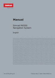
www.simrad-yachting.comA brand by Navico - Leader in Marine ElectronicsSupplied EquipmentThe following items are supplied with the <strong>MX525A</strong> DGPSSensor Kit (p/n 9525 200 81000):DescriptionPart Number<strong>MX525A</strong> DGPS Sensor 9525 200 81010with mounting kitMGL-4 Combo Antenna 721757Power/Data Cable assembly, 3 m. 3508 102 70150Installation Manual 727007The antenna coax cable for the MGL-4 antenna is notincluded in the kit and must be ordered separately.Several cable lengths are available in stock, please referto the antenna cable selection section on Page 8 for moredetails.MGL-4 ComboAntenna<strong>MX525A</strong> Black BoxSensorManual<strong>MX525A</strong>DGPS Receiver3-meter Power/Data CableInstallation Manual<strong>MX525A</strong> DGPS Sensor Kit6 | General
2 OperationGeneralThe <strong>MX525A</strong> sensor is an integrated GPS and beaconreceiver unit that is fully automatic and requiresminimal user intervention. It will automatically searchfor available satellites as soon as power is applied. Theinternal 2-channel beacon receiver continuously monitorsall beacon signals available in a particular location. Thefirst channel tracks the primary station while the secondchannel searches for other nearby beacons. Shouldit find a closer station it will automatically switch theprimary channel to the new station. The combinedperformance of the high-precision 12-channel GPS and2-channel beacon receiver provides a more accurateposition fix, usually within 2 meter or less.When controlled by an MX CDU, the operator can disablethe auto mode and manually select the beacon frequencydesired.The <strong>MX525A</strong> works with an MGL-4 (or -3) antenna (acombined GPS/H-Field Beacon antenna) for better onboardelectrical noise immunity.Satellite Bases Augmentation System(SBAS)In areas where land-based beacon stations are notavailable, the <strong>MX525A</strong> can be controlled (using the MXCDU) to track the Satellite Based Augmentation Systems(SBAS) like the WASS (US), EGNOS (European), MSAS(Japan) and GAGAN (India) satellites . These satellitestransmit DGPS correction data (just like the Coast Guardstations) using the GPS frequency. Refer to the MX CDUOperator Manual for more details. Turning this featureON in the MX CDU will initiate the <strong>MX525A</strong> to track anySBAS satellites that are in view. Please be aware thatthe SBAS system is not an IMO approved differentialcorrection system.Operation | 7
Receiver Autonomous IntegrityMonitoring (RAIM)RAIM is a special software algorithm in the <strong>MX525A</strong>program which provides another layer of safety becauseit gives the operator an alarm indication if the GPSsystem accuracy exceeds a predefined tolerance. Thisfeature requires at least five or more GPS satellites tooperate properly. If the position solution falls outside thistolerance (usually 100 meter) a “RAIM Unsafe” alarmwill be activated in the MX420 CDU. This means that theaccuracy of the position can not be guaranteed at thatpoint in time. The operator is advised to use the GPSfor navigation with caution until the RAIM indicator goesback to safe mode (R+).The RAIM availability is dependent on the number ofusable satellites in view. Planned outage of satellitesdue to maintenance or when certain satellites reach theirage of maturity may cause any of the GPS satellites tobecome unusable. If less than 5 satellites are availablea “RAIM Caution” (R?) icon will be displayed. If theGPS system error exceeds 100 meters “RAIM Unsafe”(R-) icon will be displayed. The operator should takecautionary measures during this mode.8 | Operation
3 Installation<strong>MX525A</strong> MountingThe <strong>MX525A</strong> console is not weather-resistant and mustbe located inside the equipment room or pilot housewhere it is dry and protected from the elements. Provideample clearance around it for good air circulation. Usethe supplied mounting bracket kit to mount it on avertical wall.Locate the <strong>MX525A</strong> within 3 meters from the MX CDUjunction box. Should there be a need to install the<strong>MX525A</strong> much farther away from the MX420 CDU, alonger cable assembly can be specially ordered from<strong>Simrad</strong>.The MGL-4 antenna is a weather resistant unit and shouldbe mounted in the open location as shown in the antennalocation diagram.Below is a list of power-data cable options available from<strong>Simrad</strong>:Part NumberDescription3508 102 70150 3 meter cable3508 102 70170 20 meter cable3508 102 70180 40 meter cableSpecial order only80 meter cable<strong>MX525A</strong> ConnectorsTwo connectors are located at the back of the unit,namely:••••Power-Data connector (10-pin male)RF (TNC female)The 10-pin connector provides the means to connectto external power and the data interface. Please referto the chart below for the pin-outs and wiring colorcode. The chart also compares the signal interface ofthe <strong>MX525A</strong> DGPS sensor against the MX421B-10 smartDGPS antenna. Please note the connection similaritiesInstallation | 9
etween them on pins 1 through 8.The RF (TNC-F) connector is used to connect the <strong>MX525A</strong>to a combined DGPS antenna (MGL-3).Pin #WireColor<strong>MX525A</strong>Wiring Comparison1 BLK Negative Ground2 RED +9 - 32 VDCMX421B-103 BLU MX Proprietary Message (MPM In (-)4 BRN MX Proprietary Message (MPM In (+)5 ORG GPS Out (-)6 GRN GPS Out (+)7 YEL Beacon Status Out (-)8 WHT Beacon Status Out (+)9 PRPL RTCM IN (+) 1 PPS (+)10 PRPL/GRYTNC COAX To MGL-3 ComboAntennaRTCM IN (-) 1 PPS (-)None10 | Installation
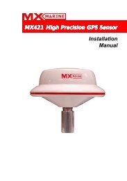
MGL-4 Antenna Mounting Guidelines•• Install the MGL-4 antenna where it has clear view ofthe sky around it.•• Locate the antenna for easy access and maintenance.•• Stay away from high-power energy sources such asradar, SSB, INMARSAT and other transmitting radioantennas by 5 meters or more.•• Locate the antenna at least 10 feet (about 3 meters)away from and out of the transmitting beam of radarand other high-power transmitters.•• Mount the antenna low to avoid excessive position andspeed errors while underway.•• Mount the antenna as far away as possible from largemetal structures.If you are not sure if the chosen antenna location isappropriate, you can mount the MGL-4 antennatemporarily and connect the coax cable to the <strong>MX525A</strong>.Using the MX CDU, Monitor the GPS signals under the“GPS Status” screen while you move the MGL-4 antennaaround.RADAR ANT.VHF or MFANT.5 m (min.)MGL-4(or MGL-3)ANT.MAINMAST10 m (min.)INMARSATANT.3 m1 m10 mmin.Mount the MGL-3 Antenna10 m (min.) forward of main mastMGL-4 Antenna location diagramInstallation | 11
Antenna MountingBracket MountThe MGL-4 antenna mounting thread is an industrystandard fitting for VHF antenna mounting (1.0 inch, 14TPI). This enables the antenna to be mounted on a widerange of mounting brackets, including the swivel joints,commonly used for angled surface. Refer to the figurebelow for bracket mounting illustration.Hand-tighten the antenna onto the bracket until snug. Donot overtighten.Secure with plastictie wraps(not supplied)1”-14 TPI StainlessSteel Mounting Bracket(not supplied)MGL-4 Bracket Mounting12 | Installation
Antenna Cable SelectionThe table below gives recommendation on coaxial cablesthat can be used for the MGL-4 GPS antenna. It isimportant to keep the attenuation in the cable as low aspossible. The maximum allowable cable and connectorloss is 15 dB.Coax cabletypeMax cablelength (m)Diameter(mm)Weight(kg/100m)RG58 15 5.0 2.6SAT45 45 5.5 2.6RG223 25 5.4 5.5RG214 45 10.8 18.5LMR400 80 10.3 13.3The chart below shows the antenna coax cables offeredby <strong>Simrad</strong>:Part numberDescription3508 100 95780 15 meter, SAT45 cable (TNC-TNC)3508 100 96010 20 meter, SAT45 cable (TNC-TNC)3508 100 95910 30 meter, SAT45 cable (TNC-TNC)3508 100 96020 45 meter, SAT45 cable (TNC-TNC)Special order>45 meter, Low-loss, Antenna cable(TNC-TNC)Power RequirementExternal power supplied to the <strong>MX525A</strong> must be within 9-32 VDC for best operation. To protect the circuitry in the<strong>MX525A</strong>, the voltage level must be within these limits.Negative grounding is required. The <strong>MX525A</strong> draws lessthan 300 mA at 12 VDC. An in-line fuse or circuit breakerrated at 2 amp. is recommended for overload protection.When the <strong>MX525A</strong> is connected to an MX CDU, the 12VDC antenna power is supplied by the CDU unit.Installation | 13
The red wire connects to the (+) DC power, while theblack wire is the negative return. Although the <strong>MX525A</strong>has a reverse polarity protection, it is prudent to makesure that proper polarity is observed before making theconnection.Reverse polarity connection may damage the unit.Power/Data Cable AssemblyBelow is a diagram showing the pins and wire colorcodingof the Power/Data cable assembly.10-Pin Female Connector3.0 metersPin#10987654321WirePrpl/GryPurpleWhiteYellowGreenOrangeBrownBlueRedBlackSignalExt. RTCM IN -Ext. RTCM IN +Beacon status Out +Beacon Status Out -GPS Out +GPS Out -MPM In +MPM In -+12-32VDCNegative GNDPower/Data Cable Assembly14 | Installation
<strong>MX525A</strong> Connector ConfigurationRefer to the diagram below for the POWER-DATAconnector located at the rear panel of the <strong>MX525A</strong>:RFPOWERDATA? ??? ?? ?? ?? ?TNCConnectorPin#10987654321WirePrpl/GryPurpleWhiteYellowGreenOrangeBrownBlueRedBlackSignalExt. RTCM IN -Ext. RTCM IN+Beacon status Out +Beacon status Out -GPS Out +GPS Out -MPM In+MPM In -+12-32VDCNegative GNDWhere:Pins 1 & 2:Pins 3 & 4:Pins 5 & 6:Pins 7 & 8:<strong>MX525A</strong> POWER-DATA ConnectorNegative GND and +12 VDC powerinput.MX proprietary message (MPM) inputport.GPS output to the MX420 or otherNMEA 0183 compatible devices.Beacon monitoring signal output. Sendsthe SNR, Signal and Frequency to theMX420/8 CDU. Connects to Cable B ofthe MX420/8 CDU.Pins 9 & 10: External RTCM Correction (Input).Installation | 15
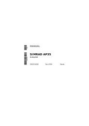
Data Interface to MX420/2 or MK12CDUUse the diagram below to interface the <strong>MX525A</strong> to anMX420/2 or MK12 CDU.MGL-4Combo AntennaCoax Cable<strong>MX525A</strong>ConsoleMX420/2 orMk12 CDUCable A(16) Red/Wht Red (+12 VDC)(1) Blk/Shield Blk (GND)(8) OrgGrn (GPS Out +)(9) Org/WhtOrg (GPS Out -)(10) Yel(11) Yel/Blk(4) Brn(5) Brn/Wht(6) Prpl(7) Prpl/Wht(12) Grn(13) Grn/Wht(14) Blu(15) Blu/Wht(17) Gry(18) Blk/Wht(3) Blk(2) RedBrn (MPM In +)Blu (MPM In -)In (A)In (B)NMEA1 I/OOut (A)Out (B)In (A)In (B)NMEA2 I/OOut (A)Out (B)NMEA2 Tx (RS-232)Ext. AlarmTerminal strip(User supplied)+12-32VDCSupply<strong>MX525A</strong> Interface to MX420/2 or MK12 CDUs16 | Installation
Data Interface to MX420/8 or MX420/AIS CDUUse the diagram below to interface the <strong>MX525A</strong> toan MX420/8 or MX420/AIS CDU. The external RTCMconnection is optional.MGL-4Combo AntennaCoax Cable<strong>MX525A</strong>ConsoleMX420/8 CDUCable ACable B(16) Red/Wht Red (+12 VDC)(1) Blk/Shield(8) Org(9) Org/Wht(10) Yel(11) Yel/Blk(4) Brn(5) Brn/Wht(6) Prpl(7) Prpl/Wht(12) Grn(13) Grn/Wht(14) Blu(15) Blu/Wht(17) Gry(18) Blk/Wht(3) Blk(2) RedBlk (GND)Grn (GPS Out +)Org (GPS Out -)Brn (LPM In +)Blu (LPM In -)In (A)In (B)NMEA1 I/OOut (A)Out (B)In (A)In (B) NMEA2 I/OOut (A)Out (B)NMEA2 Tx (RS-232)Ext. AlarmTerminal strip(User supplied)+12-32VDCSupply(4) Brn(5) Brn/WhtWhiteYellowPurplePurple/GreyExt. RTCM (+)Ext. RTCM (-)(Optional)<strong>MX525A</strong> Interface to MX420/8 or MX420/AIS CDUsInstallation | 17
MX 5xx CDUData Interface to MX5xx CDUThe standard power/data cable (P/N 3508 102 70150)for the <strong>MX525A</strong> and MX5xx CDU is pre-made with twomolded 10-Pin male connectors for an easy plug-andplayconnection to the back of the MX5xx CDU. If there isa need to extend (or cut) the standard cable, please referto the diagram below for the wire splice.P/N 3508 102 701503 MTR. CABLE ASSY.<strong>MX525A</strong>MX 5xx CDU<strong>MX525A</strong>REDBLKBLUBRNORGYELPRPLGRYREDBLKBLUBRNORGYELPRPLGRY<strong>MX525A</strong> Interface to MX5xx CDU’s18 | Installation
Data Interface to PC or othernavigation systemsThe diagram below shows the power and data outputconnections to the serial port of a PC or other navigationsystems using a dB9 connector and a terminal strip (userMGL-4Combo AntennaCoax Cable<strong>MX525A</strong>Console1 2 3 4 5 6 7 8 9Brn (MPM In +)Blu (MPM In -)Grn (GPS Out +)Org (GPS Out -)Red (+12 VDC)Blk (GND)9dB PC connector+12-32VDCSupplysupplied items).<strong>MX525A</strong> Interface to other navigation systemsInstallation | 19
<strong>MX525A</strong> Programming CableThe programming cable is used for upgrading thesoftware of the GPS and Beacon PCBs inside the <strong>MX525A</strong>Console. The diagram below shows the programmingcable diagram and equipment setup. Please note thatexternal 12 volt DC is required to power up the <strong>MX525A</strong>.Connect the red wire to +12 VDC and Black wire tonegative GND. The RS422-RS232 converter may bepowered from the PC serial port or from an external 12volt power supply.3 metersRS422+12-32 VDCRS232NEGREDBLK10-pin Male ConnectorBRNBLUGRNORGSecure cable with tie-wrapTD(A)TD(B)RD(A)RD(B)GND+12VB&B ElectronicsRS422-RS232ConverterModel 422LP9TB<strong>MX525A</strong>RS422-RS232ConverterCOM1PC12 VDC<strong>MX525A</strong> Programming cable diagram20 | Installation
4 SpecificationsGPS ReceiverType:....................................................... L1, C/A Code (SPS)1.575 GHz frequencyChannels:................................... 12 Channels, parallel tracking(10-channel when tracking WAAS/EGNOS/MSAS)Position Update Rate:..................1 Hz (default), 5 Hz (optional)Position accuracy:With differential corrections....................
Frequency offset tolerance: ......................................... + 5 HzAntenna type:............................................................ H-FieldMSK rates:..............................................50, 100 and 200 bpsEnvironmental<strong>MX525A</strong> ConsoleOperating Temperature:..................................... -30 to +55 °CStorage Temperature:........................................-40 to +85 °CHumidity:..................95% non-condensing, protected categoryMGL-3 AntennaOperating Temperature:..................................... -30 to +70 °CStorage Temperature:........................................-40 to +85 °CSplashproof:.......................... “Exposed Category” (IEC 60945)Electrical<strong>MX525A</strong> ConsoleOperating Voltage:.......................................... 10.5 to 32 VDCReverse Polarity Protection:..............................................YesOperating current: .............................< 230 mA at 12.0 VDC,Power Consumption:................................................
Power/Data Connector:... 3-meter, 10-wire Shielded Twisted PairAntenna Connector: ........................................... TNC (female)MGL-3Dimensions:............... 12.7 cm (L) x 12.7 cm. (W) x 7.6 cm. (H)Weight: ....................................................460 grams (1.0 lb.)Antenna Connector: ........................................... TNC (female)Mount:............................................................... 1 in.- 14 TPICertificationsBSH and Wheelmark IMO MSC 112(73) approvedIEC 60945 ed.3, CE, and FCC compliant<strong>Simrad</strong> reserves the right to make changes in itsproducts and specifications without notice.12.7 cm (5”)7.6 cm (3”)MGL-4 Combo Antenna1”-14 TPIMount13.5 cm<strong>MX525A</strong> ConsoleSpecifications | 23
24 | SpecificationsBlank page
5 Data OutputThe <strong>MX525A</strong> data output conforms to the NMEA0183 V3.0 at 4800 baud. Below is a list of the NMEAsentences output:NMEA 0183 V3.0: GGA, GLL, GSA, GSV, GST, RMC andVTGNMEA 0183 Data Output Sentences(1) GGA - Global Positioning System Fix DataTime, position and fix related data for a GPS receiver.$GPGGA,hhmmss,llll.llll,a,yyyyy.yyyy,a,x,xx,x.x,x.x,M,x.x,M,x.x,xxxx*hh
(2) GLL - Geographic Position - Latitude/LongitudeLatitude and Longitude of vessel position, time ofposition fix and status.$GPGLL,llll.llll,a,yyyyy.yyyy,a,hhmmss.ss,A,a*hh
16 ---HDOP17 ---VDOP(4) GSV - GPS Satellite in ViewNumber of satellites (SV) in view, PRN numbers,elevation, azimuth and SNR values. Four satellitesmaximum per transmission, additional satellite data sentin second or third message. Total number of messagesbeing transmitted and the number of the messagetransmitted are indicated in the first two fields.$GPGSV,x,x,xx,xx,xx,xxx,xx,....................,xx,xx,xxx,xx*hh1 2 3 4 5 6 7 8 9 10 11 12Notes: 1 -----Total number of messages, 1 to 32 ---- Message number, 1 to 33 ---- Total number of satellites in view4 ----- Satellite PRN number5 ----- Elevation, degrees, 90 degrees maximum6 ------Azimuth, degrees True, 000 to 3597 ------SNR (C/No) 00-99 dB, null when nottracking8 ------2nd and 3rd SV9,10,11,12 - 4th SV(5) RMC - Recommended Minimum Specific GPS DataTime, date, position, course and speed data provided bya GPS navigation receiver. This sentence is transmittedat intervals not exceeding 2 seconds. All data fieldsmust be provided: null fields used only when data istemporarily unavailable.$GPRMC,hhmmss.ss,A,llll.llll,a,yyyyy.yyyy,a,x.x,x.x,xxxxxx,x.x,a*hh1 2 3 4 5 6 7 8 9 10 11Notes: 1 ---- UTC of Position fix2 ---- Status: A = data validV = Navigation receiver warningData output | 27
3,4 -- Latitude, N/S5,6 -- Longitude, E/W7 ---- Speed over ground, knots8 ---- Course Over Ground, True9 ---- Date: dd/mm/yy10,11 - Magnetic variation, degrees E/W.Easterly variation (E) subtracts fromTrue course, Westerly variation (W) addsto True course.(6) GST - GNSS Pseudorange Error StatisticsThis message is used to support Receiver AutonomousIntegrity Monitoring (RAIM). Pseudorange measurementerror statistics can be translated in the position domainin order to give statistical measures of the quality of theposition solution.If only GPS, GLONASS, etc. is used for the reportedposition solution, the talker ID is GP, GL, etc., and theerror data pertains to the individual system. If satellitesfrom multiple systems are used to obtain the reportedposition solution, the talker ID is GN and the errorspertain to the combined solution.$GPGST,hhmmss.ss,x.x,x.x,x.x,x.x,x.x,x.x,x.x*hh1 2 3 4 5 6 7 8Notes: 1 ---- UTC time of the GGA or GNS fix associatedwith this sentence.2 ---- RMS value of the standard deviation of therange inputs to the navigation process.Range inputs include preudoranges &DGNSS corrections.3 ---- Standard deviation of semi-major axis oferror ellipse (meters)4 ---- Standard deviation of semi-minor axis oferror ellipse (meters)5 ---- Orientation of semi-major axis of errorellipse (degrees from true north)28 | Data output
6 ---- Standard deviation of latitude error(meters)7 ---- Standard deviation of longitude error(meters)8 ---- Standard deviation of altitude error(meters)(7) VTG - Course Over Ground and Ground SpeedThe actual course and speed relative to the ground.$GPVTG,x.x,T,x.x,M,x.x,N,x.x,K,a*hhNotes: 1,2 ---- Course over ground, degrees True2,3 ---- Course over ground, degrees Magnetic5,6 ---- Speed over ground, knots7,8 ---- Speed over ground, km/hr9 ------ Mode indicator: A = Autonomous mode(8) ZDA -Time and DateUTC, day, month, year and local time zoneNotes: 1 --- UTC1 2 3 4 5 6 7 8 9D = Differential modeE = Estimated (DR)M = Manual input modeS = Simulator modeN = Data not valid$GPZDA,hhmmss,xx,xx,xxxx,xx,xx*hh1 2 3 4 5 62, 3, 4 --- Day, month & year5 --- Local zone hours, 00 to + 13 hrs.6 --- Local zone in minutes, 00 to +59.Data output | 29
(9) GBS - GNSS Satellite Fault Detection (Modified MXversion)This message is used to support Receiver AutonomousIntegrity Monitoring (RAIM) feature in the MX420 CDU. Aspecial character flag was added for proper RAIM statusdetermination.$PMVXG,GBS,hhmmss.ss,x.x,x.x,x.x,xx,x.x,x.x,x.x,x*hh1 2 3 4 5 6 7 8 9Notes: 1 ----- UTC time of the GGA or GNS fixassociated with this sentence.2 ----- Expected error in Latitude (meters)3 ----- Expected error in Longitude (meters)4 ----- Expected error in Altitude (meters)5 ----- ID number of most likely failed satellite6 ----- Probability of missed detection for mostlikely failed satellite7 ----- Estimate of bias in meters on most likelyfailed satellite8 ----- Standard deviation of bias estimate9 ----- RAIM status mode; 0=safe, 1=caution,2=unsafe30 | Data output
How are we doing?Please help us to help you and our other valuedcustomers by sending us your evaluation of this manual.We need to know such things as:--------is the manual complete, or do you need more (or less)information?can you find the information you need easily?is the information easy to understand, or could we beclearer?are there any errors and, if so, where and what arethey?Be sure to reference the title and identification numberof this manual.Please email your comments to: tech.writing@navico.com.We look forward to finding out how we can improve ourinformation services.All of your comments and suggestions become theproperty of Navico Holding AS.Data output | 31
32 | Data outputBlank page
Doc.no.727007, Rev.A