Defects in nanocrystalline Nb films: Effect of sputtering temperature
Defects in nanocrystalline Nb films: Effect of sputtering temperature
Defects in nanocrystalline Nb films: Effect of sputtering temperature

You also want an ePaper? Increase the reach of your titles
YUMPU automatically turns print PDFs into web optimized ePapers that Google loves.
Applied Surface Science 252 (2006) 3245–3251www.elsevier.com/locate/apsusc<strong>Defects</strong> <strong>in</strong> nanocrystall<strong>in</strong>e <strong>Nb</strong> <strong>films</strong>: <strong>Effect</strong><strong>of</strong> sputter<strong>in</strong>g <strong>temperature</strong>J. Čížek a, *, O. Melikhova a , I. Procházka a , G. Brauer b , W. Anwand b ,A. Mücklich b , R. Kirchheim c , A. Pundt ca Department <strong>of</strong> Low-Temperature Physics, Faculty <strong>of</strong> Mathematics and Physics,Charles University, V Holešovičkách 2, CZ-180 00, Prague 8, Czech Republicb Institut für Ionenstrahlphysik und Materialforschung, Forschungszentrum Rossendorf, Dresden, Germanyc Institut für Materialphysik, Universität Gött<strong>in</strong>gen, GermanyAvailable onl<strong>in</strong>e 7 October 2005AbstractTh<strong>in</strong> niobium (<strong>Nb</strong>) <strong>films</strong> (thickness 350–400 nm) were prepared on (1 0 0)Si substrate <strong>in</strong> a UHV chamber us<strong>in</strong>g the cathodebeam sputter<strong>in</strong>g. The sputter<strong>in</strong>g <strong>temperature</strong> T s was varied from 40 up to 500 8C and the <strong>in</strong>fluence <strong>of</strong> the sputter<strong>in</strong>g <strong>temperature</strong>on the microstructure <strong>of</strong> th<strong>in</strong> <strong>Nb</strong> <strong>films</strong> was <strong>in</strong>vestigated. Defect studies <strong>of</strong> the th<strong>in</strong> <strong>Nb</strong> <strong>films</strong> sputtered at various <strong>temperature</strong>swere performed by slow positron implantation spectroscopy (SPIS) with measurement <strong>of</strong> the Doppler broaden<strong>in</strong>g <strong>of</strong> theannihilation l<strong>in</strong>e. SPIS was comb<strong>in</strong>ed with transmission electron microscopy (TEM) and X-ray diffraction (XRD). We havefound that the <strong>films</strong> sputtered at T s =408C exhibit elongated, column-like nanocrystall<strong>in</strong>e gra<strong>in</strong>s. No significant <strong>in</strong>crease <strong>of</strong>gra<strong>in</strong> size with T s (up to 500 8C) was observed by TEM. The th<strong>in</strong> <strong>Nb</strong> <strong>films</strong> sputtered at T s =408C conta<strong>in</strong> a high density <strong>of</strong>defects. It is demonstrated by shortened positron diffusion length and a high value <strong>of</strong> the S parameter for <strong>Nb</strong> layer compared tothe well-annealed (defect-free) bulk <strong>Nb</strong> reference sample. A drastic decrease <strong>of</strong> defect density was found <strong>in</strong> the <strong>films</strong> sputtered atT s 300 8C. It is reflected by a significant <strong>in</strong>crease <strong>of</strong> the positron diffusion length and a decrease <strong>of</strong> the S parameter for the <strong>Nb</strong>layer. The defect density <strong>in</strong> the <strong>Nb</strong> layer is, however, still substantially higher than <strong>in</strong> the well-annealed reference bulk <strong>Nb</strong>sample. Moreover, there is a layer at the <strong>in</strong>terface between the <strong>Nb</strong> film and the substrate with very high density <strong>of</strong> defectscomparable to that <strong>in</strong> the <strong>films</strong> sputtered at T s < 300 8C. All the <strong>Nb</strong> <strong>films</strong> studied exhibit a strong (1 1 0) texture. The <strong>films</strong>sputtered at T s < 300 8C are characterized by a compressive macroscopic <strong>in</strong>-plane stress due to lattice mismatch between thefilm and the substrate. Relaxation <strong>of</strong> the <strong>in</strong>-plane stress was observed <strong>in</strong> the <strong>films</strong> sputtered at T s 300 8C. The width <strong>of</strong> the XRDpr<strong>of</strong>iles <strong>of</strong> the <strong>films</strong> sputtered at T s 300 8C is significantly smaller compared to the <strong>films</strong> sputtered at lower <strong>temperature</strong>s. Thisis most probably due to a lower defect density which results <strong>in</strong> reduced microstra<strong>in</strong>s <strong>in</strong> the <strong>films</strong> sputtered at higher <strong>temperature</strong>s.# 2005 Elsevier B.V. All rights reserved.Keywords: Niobium <strong>films</strong>; Cathode beam sputter<strong>in</strong>g; Slow positron implantation spectroscopy; X-ray diffraction* Correspond<strong>in</strong>g author. Tel.: +420 2 2191 2788; fax: +420 2 2191 2567.E-mail address: jcizek@mbox.troja.mff.cuni.cz (J. Čížek).0169-4332/$ – see front matter # 2005 Elsevier B.V. All rights reserved.doi:10.1016/j.apsusc.2005.08.083
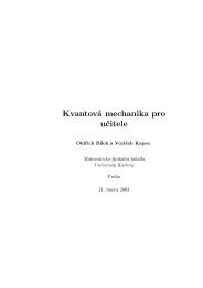
3246J. Čížek et al. / Applied Surface Science 252 (2006) 3245–32511. IntroductionThe growth mode <strong>of</strong> th<strong>in</strong> <strong>films</strong> prepared bysputter<strong>in</strong>g is <strong>in</strong>fluenced by the sputter<strong>in</strong>g rate (i.e.the number <strong>of</strong> atoms which hit the substrate per unit <strong>of</strong>time) and by the sputter<strong>in</strong>g <strong>temperature</strong> T s (the<strong>temperature</strong> <strong>of</strong> substrate). Higher T s leads to anenhanced mobility <strong>of</strong> the sputtered atoms <strong>in</strong> thesubstrate plane and long-range diffusion processesstart to play an important role <strong>in</strong> the growth <strong>of</strong> the film.The effect <strong>of</strong> T s is clearly visible on niobium (<strong>Nb</strong>)<strong>films</strong> [1]: polycrystall<strong>in</strong>e <strong>Nb</strong> <strong>films</strong> are produced bysputter<strong>in</strong>g at room <strong>temperature</strong>, while a high sputter<strong>in</strong>g<strong>temperature</strong> T s = 850 8C results <strong>in</strong> a formation <strong>of</strong>epitaxial <strong>films</strong>. One can expect that the sputter<strong>in</strong>g<strong>temperature</strong> <strong>in</strong>fluences not only the gra<strong>in</strong> size but alsothe density and type <strong>of</strong> lattice defects <strong>in</strong> th<strong>in</strong> <strong>films</strong>.Thus, it is highly desirable to perform defect studies <strong>of</strong>th<strong>in</strong> <strong>films</strong> sputtered at various T s . The characterization<strong>of</strong> th<strong>in</strong> <strong>films</strong> prepared by sputter<strong>in</strong>g is usuallyperformed by X-ray diffraction (XRD). The shape<strong>of</strong> the diffraction pr<strong>of</strong>ile is <strong>in</strong>fluenced by gra<strong>in</strong> size aswell as microstra<strong>in</strong>s which could orig<strong>in</strong>ate, e.g. fromdislocations. On the other hand, po<strong>in</strong>t defects (e.g.vacancies) can only hardly be detected by XRD. Forthese reasons positron annihilation spectroscopy(PAS) is very useful for defect studies <strong>of</strong> th<strong>in</strong> <strong>Nb</strong><strong>films</strong> because it exhibits a high sensitivity to openvolumepo<strong>in</strong>t defects like vacancies, vacancy clusters,etc. [2]. Hence, XRD and PAS represent <strong>in</strong> certa<strong>in</strong> waycomplementary techniques and their comb<strong>in</strong>ation <strong>in</strong><strong>in</strong>vestigations <strong>of</strong> th<strong>in</strong> <strong>films</strong> is very efficient.In the present work we <strong>in</strong>vestigated the microstructure<strong>of</strong> th<strong>in</strong> <strong>Nb</strong> <strong>films</strong> prepared at various T s . <strong>Defects</strong>tudies <strong>of</strong> the <strong>films</strong> were performed by slow positronimplantation spectroscopy (SPIS) with measurement <strong>of</strong>the Doppler broaden<strong>in</strong>g <strong>of</strong> the annihilation l<strong>in</strong>e. TheSPIS <strong>in</strong>vestigations were comb<strong>in</strong>ed with XRD studiesand direct observation <strong>of</strong> the microstructure bytransmission electron microscopy (TEM). The purpose<strong>of</strong> this work was to clarify the <strong>in</strong>fluence <strong>of</strong> T s on themicrostructure <strong>of</strong> th<strong>in</strong> <strong>Nb</strong> <strong>films</strong>.2. Experimental detailsTh<strong>in</strong> <strong>Nb</strong> <strong>films</strong> were prepared on polished (1 0 0)Sisubstrates <strong>in</strong> an UHV chamber us<strong>in</strong>g cathode beamsputter<strong>in</strong>g at sputter<strong>in</strong>g <strong>temperature</strong>s T s = 40, 100,200, 300, 400 and 500 8C. The desired T s wasstabilized dur<strong>in</strong>g sputter<strong>in</strong>g with<strong>in</strong> 1 8C. In addition,one <strong>Nb</strong> film was sputtered at T s =408C andsubsequently annealed at 500 8C for 1 h <strong>in</strong> UHV(10 10 mbar). The surface <strong>of</strong> all samples was coveredwith a 20 nm thick Pd cap <strong>in</strong> order to preventoxidation. The thickness <strong>of</strong> the <strong>films</strong> was measured byTEM and found to lie <strong>in</strong> the range 350–400 nm forvarious <strong>films</strong>. The SPIS studies were performed at amagnetically guided positron beam ‘‘SPONSOR’’ [3]with positron energies adjustable from 0.03 to 36 keV.Energy spectra <strong>of</strong> annihilation gamma rays weremeasured by a Ge detector with an energy resolution<strong>of</strong> 1.09 0.01 keV at 511 keV. The texture measurementswere carried out on a four-axis Philips X’pertMPD diffractometer us<strong>in</strong>g Co Ka radiation. XRDmeasurements <strong>of</strong> lattice constants were performed atHasylab (DESY) us<strong>in</strong>g synchrotron radiation withwavelength l = 1.13 Å. The <strong>in</strong>ter-planar distance wasmeasured <strong>in</strong> the out-<strong>of</strong>-plane direction (i.e. <strong>in</strong> thedirection perpendicular to the film surface, whichcorresponds to c =08) and <strong>in</strong> the directions tilted byc =458 and 608 with respect to normal to the surface.In such a way, we obta<strong>in</strong>ed <strong>in</strong>formation about stress <strong>in</strong>the studied <strong>films</strong>. Diffraction pr<strong>of</strong>iles were fitted by thePearson VII function. TEM studies were performedwith a Philips CM300SuperTWIN microscope operat<strong>in</strong>gat 300 kV. Th<strong>in</strong> foils for cross sectional TEMwere produced by conventional preparation us<strong>in</strong>gGatan precision ion polish<strong>in</strong>g system (PIPS).3. Results and discussionA bright field TEM image <strong>of</strong> the film sputtered atT s =408C is shown <strong>in</strong> Fig. 1a. The film exhibitselongated ‘‘column-like’’ gra<strong>in</strong>s. The width <strong>of</strong>columns does not exceed 100 nm. Typically it liesaround 50 nm. A high resolution image <strong>of</strong> a column isshown <strong>in</strong> Fig. 1b. The columns are divided horizontally(i.e. <strong>in</strong> direction perpendicular to film-grow<strong>in</strong>gdirection) <strong>in</strong>to two ‘‘generations’’ <strong>of</strong> sub-columns.The ‘‘first generation’’ sub-columns are situated closeto the Si substrate, while the ‘‘second generation’’ subcolumnsare situated close to the film surface. A brightfield TEM image <strong>of</strong> the film sputtered at T s = 500 8Cisshown <strong>in</strong> Fig. 2a. From comparison <strong>of</strong> Figs. 1a and 2a
J. Čížek et al. / Applied Surface Science 252 (2006) 3245–3251 3247Fig. 1. (a) A bright field TEM image <strong>of</strong> the film sputtered at T s =408C and (b) a high resolution image <strong>of</strong> a s<strong>in</strong>gle column-like gra<strong>in</strong> <strong>in</strong> the film.it is clear that there is basically no differencedetectable by TEM between the film sputtered at40 8C and at 500 8C. A high resolution TEM image <strong>of</strong>the film sputtered at 500 8C is shown <strong>in</strong> Fig. 2b.A strong 1 1 0 texture was found <strong>in</strong> all the studied<strong>films</strong>. Most <strong>of</strong> gra<strong>in</strong>s are oriented so that the {1 1 0}planes are situated parallel with the film surface.However, the lateral orientation <strong>of</strong> gra<strong>in</strong>s is random.The texture becomes better developed at higher T s .In order to illustrate the effect <strong>of</strong> T s on the X-raydiffraction pattern, the XRD pr<strong>of</strong>iles correspond<strong>in</strong>g to(1 1 0)<strong>Nb</strong> reflection for selected <strong>films</strong> sputtered atvarious T s are shown <strong>in</strong> Fig. 3a and b. The pr<strong>of</strong>ilesshown <strong>in</strong> Fig. 3a were measured <strong>in</strong> the directionc =08, i.e. the scatter<strong>in</strong>g vector is perpendicular tothe film surface. The XRD pr<strong>of</strong>iles plotted <strong>in</strong> Fig. 3bwere measured on tilted sample at position c =608,i.e. the angle <strong>in</strong>cluded by the scatter<strong>in</strong>g vector and thenormal to the film surface is 608. Thus, the <strong>in</strong>terplanardistance determ<strong>in</strong>ed from position <strong>of</strong> thereflections <strong>in</strong> Fig. 3a and b, respectively, correspondto the distance between the {1 1 0} planes <strong>in</strong> the out<strong>of</strong>-planedirection and <strong>in</strong> the direction tilted by 608with respect to normal to the film surface. Thedistance d 110 between the {1 1 0} planes <strong>in</strong> bulk <strong>Nb</strong>is <strong>in</strong>dicated <strong>in</strong> Fig. 3a and b by a dashed l<strong>in</strong>e. One cansee from Fig. 3a that d 110 <strong>in</strong> the direction c =08 ishigher than that for bulk <strong>Nb</strong> <strong>in</strong> all the <strong>films</strong> studied.On the other hand, d 110 <strong>in</strong> the direction c =608 isslightly smaller than <strong>in</strong> bulk <strong>Nb</strong>. It <strong>in</strong>dicates anexistence <strong>of</strong> compressive <strong>in</strong>-plane stresses <strong>in</strong> the <strong>films</strong>caused by a lattice mismatch between the film and theSi substrate. The magnitude <strong>of</strong> the compressive stressdecreases with <strong>in</strong>creas<strong>in</strong>g T s , which is reflected by ashift <strong>of</strong> the reflections towards the positions for bulk<strong>Nb</strong>. One can see from Fig. 3a that there is a significantFig. 2. (a) A bright field TEM image <strong>of</strong> the film sputtered at T s = 500 8C and (b) a high resolution image <strong>of</strong> a s<strong>in</strong>gle column-like gra<strong>in</strong> <strong>in</strong> the film.
3248J. Čížek et al. / Applied Surface Science 252 (2006) 3245–3251Fig. 3. XRD pr<strong>of</strong>iles for selected <strong>films</strong> measured at position (a) c =08 and (b) c =608. Thicker solid l<strong>in</strong>e, T s =408C; dotted l<strong>in</strong>e, T s = 200 8C;dashed l<strong>in</strong>e, T s = 300 8C; th<strong>in</strong> solid l<strong>in</strong>e, T s = 500 8C; dash-dotted l<strong>in</strong>e, T s =408C with subsequent anneal<strong>in</strong>g at 500 8C for 1 h. The d 110 <strong>in</strong>terplanardistance <strong>in</strong> the bulk <strong>Nb</strong> is <strong>in</strong>dicated by the vertical-dashed l<strong>in</strong>es.change <strong>of</strong> the position <strong>of</strong> the (1 1 0) reflection forT s 300 8C. Thus, start<strong>in</strong>g from T s = 300 8C thecompressive stresses <strong>in</strong> the <strong>films</strong> are partially relaxed.Not only the position but also the width <strong>of</strong> thereflections depends strongly on T s . The broaden<strong>in</strong>g <strong>of</strong>XRD pr<strong>of</strong>iles is caused either by small gra<strong>in</strong> size or bymicrostra<strong>in</strong>s <strong>in</strong>duced by local elastic field <strong>of</strong> certa<strong>in</strong>defects, e.g. misfit dislocations. From Fig. 3a itisclear that the sample prepared at T s =5008C exhibitsthe narrowest XRD pr<strong>of</strong>ile. On the other hand, thehighest width <strong>of</strong> the XRD pr<strong>of</strong>ile was found on thefilm sputtered at T s =408C. As no difference <strong>in</strong> gra<strong>in</strong>size between these two samples has been observed byTEM, we conclude that the narrow<strong>in</strong>g <strong>of</strong> XRD pr<strong>of</strong>ilefor the film sputtered at T s =5008C is due to adecrease <strong>of</strong> defect density. The <strong>in</strong>crease <strong>of</strong> T s from 40to 200 8C leads to a decrease <strong>of</strong> width <strong>of</strong> XRD pr<strong>of</strong>ilescaused by a decrease <strong>of</strong> defect density. However, therelaxation <strong>of</strong> compressive stresses at T s =3008Cwhich leads to a shift <strong>of</strong> the peak position isaccompanied by an <strong>in</strong>crease <strong>of</strong> the width <strong>of</strong> thereflection, see Fig. 3a. It could be due to <strong>in</strong>troduction<strong>of</strong> misfit dislocations which accommodate thestresses caused by the lattice mismatch. Further<strong>in</strong>crease <strong>of</strong> T s from 300 to 500 8C leads aga<strong>in</strong> to asignificant narrow<strong>in</strong>g <strong>of</strong> XRD pr<strong>of</strong>iles due to decrease<strong>of</strong> defect concentration <strong>in</strong> the film. Note that the <strong>films</strong>puttered at T s =408C and subjected to subsequentanneal<strong>in</strong>g at 500 8C is characterized by relaxation <strong>of</strong>the stresses, i.e. a shift <strong>of</strong> the peak position towardsthat for bulk <strong>Nb</strong>, however, the width <strong>of</strong> the pr<strong>of</strong>ilerema<strong>in</strong>s large. It <strong>in</strong>dicates that defect density <strong>in</strong> thisfilm is comparable with the film sputtered atT s =408C.The reflection measured at c =08 for the <strong>films</strong>puttered at T s =408C is asymmetric. It can be wellseen <strong>in</strong> Fig. 4a where it is plotted <strong>in</strong> a f<strong>in</strong>er scale. Theshape <strong>of</strong> the pr<strong>of</strong>ile <strong>in</strong>dicates that it is a superpositionFig. 4. (a) XRD pr<strong>of</strong>ile for the film sputtered at T s =408C, measured <strong>in</strong> position c =08 and (b) XRD pr<strong>of</strong>ile for the film sputtered at T s = 300 8C,measured <strong>in</strong> position c =08. The pr<strong>of</strong>ile is a superposition <strong>of</strong> several reflections shown by the dotted l<strong>in</strong>es.
J. Čížek et al. / Applied Surface Science 252 (2006) 3245–3251 3249<strong>of</strong> several reflections, namely: (i) the (1 1 0) reflectionfrom the ‘‘first generation’’ sub-columns <strong>in</strong> <strong>Nb</strong> layer,(ii) the (1 1 0) reflection from the ‘‘second generation’’sub-columns <strong>in</strong> <strong>Nb</strong> layer and (iii) a weak andbroad (1 1 1) reflection from the Pd cap. Note that it isnot possible to fit the XRD pr<strong>of</strong>ile properly without theassumption <strong>of</strong> different distances d 110 <strong>in</strong> the ‘‘firstgeneration’’ and <strong>in</strong> the ‘‘second generation’’ subcolumns.The same result was obta<strong>in</strong>ed on a thicker(1.1 mm) <strong>Nb</strong> film sputtered under the same conditions(see ref. [4] for more detailed discussion). Theasymmetry <strong>of</strong> XRD pr<strong>of</strong>iles disappears at T s 300 8C8C and the pr<strong>of</strong>iles are then well-fitted by a s<strong>in</strong>gle(1 1 0) reflection from the <strong>Nb</strong> layer and the reflectionfrom Pd cap. As an example, the XRD pr<strong>of</strong>ile for thefilm sputtered at T s = 300 8C is shown <strong>in</strong> Fig. 3b.Additionally, the <strong>in</strong>ter-planar distance d 110(<strong>Nb</strong>(1 1 0) reflection) <strong>in</strong> the direction c =608 andthe distance d 200 (<strong>Nb</strong>(2 0 0) reflection) <strong>in</strong> thedirection c =458 were measured. Both the d 110and d 200 distances for the two generations <strong>of</strong> subcolumnslie <strong>in</strong> these directions too close to each otherto separate their reflections <strong>in</strong> XRD spectrum.The lattice constants a calculated from the <strong>in</strong>terplanardistance <strong>in</strong> the directions c =08,458 and 608 areplotted <strong>in</strong> Fig. 5a as a function <strong>of</strong> T s . The lattice constantfor bulk <strong>Nb</strong> [5] is shown <strong>in</strong> the figure by a dashed l<strong>in</strong>e.Below T s = 300 8C, the <strong>in</strong>ter-planar distance <strong>in</strong> the two‘‘generations’’ <strong>of</strong> sub-columns differs <strong>in</strong> the directionc =08. The ‘‘first generation’’ sub-columns exhibit ahigher d 110 <strong>in</strong> this direction than the ‘‘secondgeneration’’ sub-columns. On the other hand, aboveT s = 300 8C, there is no significant difference betweend 110 <strong>in</strong> both ‘‘generations’’ <strong>of</strong> sub-columns and thereis only a s<strong>in</strong>gle value <strong>of</strong> a for c =08. One can see <strong>in</strong>Fig. 5a that a <strong>in</strong> the direction c =08 lies significantlyabove that for bulk <strong>Nb</strong>. A progressive decrease <strong>of</strong> atakes place from T s = 40–200 8C, while at higherT s > 300 8C it becomes approximately constant. Thevalues <strong>of</strong> a <strong>in</strong> the direction c =608 are lower than <strong>in</strong> thebulk <strong>Nb</strong>. It testifies the existence <strong>of</strong> compressivestresses <strong>in</strong> the <strong>in</strong>-plane direction <strong>in</strong> all the <strong>films</strong> studied.Only moderate changes <strong>of</strong> a with T s can be seen <strong>in</strong> thedirections c =458 and 608. The ma<strong>in</strong> feature is adecrease <strong>of</strong> a at T s = 300 8C. Anneal<strong>in</strong>g <strong>of</strong> the film at500 8C after sputter<strong>in</strong>g (T s =408C) leads to asubstantial decrease <strong>of</strong> a, see Fig. 5a, which becomeseven lower than that for the film sputtered atT s = 500 8C. Thus, anneal<strong>in</strong>g <strong>of</strong> the as-sputtered <strong>films</strong>seems to be an effective way how to relax thecompressive stresses.The dependence <strong>of</strong> the S parameter on positronenergy E for selected <strong>Nb</strong> <strong>films</strong> is plotted <strong>in</strong> Fig. 5b. Alocal m<strong>in</strong>imum <strong>of</strong> S at E = 1 keV is due to positronannihilations <strong>in</strong> the Pd cup. It was confirmed bymeasurement <strong>of</strong> a reference Pd film. Subsequent<strong>in</strong>crease <strong>of</strong> S is caused by an <strong>in</strong>creas<strong>in</strong>g fraction <strong>of</strong>positrons annihilat<strong>in</strong>g <strong>in</strong>side the <strong>Nb</strong> layer. In theenergy range from 5 to 7 keV, the contribution <strong>of</strong>positron annihilations <strong>in</strong>side the <strong>Nb</strong> layer is maximaland S exhibits a plateau-like behavior. At higherenergies, positrons start to penetrate <strong>in</strong>to the SiFig. 5. (a) The lattice constant a determ<strong>in</strong>ed from <strong>in</strong>ter-planar distances <strong>in</strong> various directions as a function <strong>of</strong> T s . Full circles, direction c =08,‘‘first generation’’ sub-columns; open circles, direction c =08, ‘‘second generation’’ sub-columns; full squares, direction c =08, both‘‘generations’’ <strong>of</strong> sub-columns (T s 300 8C); full triangles, direction c =458; open triangles, direction c =458, the gray symbols correspondsto the film sputtered at T s =408C and subjected to subsequent anneal<strong>in</strong>g at 500 8C; gray circle, direction c =458; gray triangle oriented-up,c =458; gray triangle oriented-down, c =608 and (b) dependencies <strong>of</strong> the S parameter on positron energy E for selected <strong>films</strong>. The solid l<strong>in</strong>esshow the fit performed by VEPFIT.
3250J. Čížek et al. / Applied Surface Science 252 (2006) 3245–3251Fig. 6. Results <strong>of</strong> fit <strong>of</strong> the S(E) curves (a) dependence <strong>of</strong> fitted S on T s ; full circles, S for the <strong>Nb</strong> layer; open circles, S for the layer with misfitdislocations situated close to the <strong>in</strong>terface between the <strong>films</strong> and the substrate; full triangle, S for the <strong>Nb</strong> layer for the film sputtered at T s =408Cand subjected to subsequent anneal<strong>in</strong>g at 500 8C; open triangle, S for the layer with misfit dislocations for the film sputtered at T s =408C andsubjected to subsequent anneal<strong>in</strong>g at 500 8C and (b) dependence <strong>of</strong> positron diffusion length on T s ; full circles, <strong>Nb</strong> layer; open circles, the layerwith misfit dislocations, the triangles denote the results for the film sputtered at T s =408C and subjected to subsequent anneal<strong>in</strong>g at 500 8C; fulltriangle, <strong>Nb</strong> layer; open triangle, the layer with misfit dislocations.substrate which leads to further <strong>in</strong>crease <strong>of</strong> S. As onecan see <strong>in</strong> Fig. 5b, there is not much differencebetween the S(E) curves for T s = 40 and 200 8C as wellas for the film sputtered at T s =408C and subjected toadditional anneal<strong>in</strong>g at 500 8C. On the other hand, theshape <strong>of</strong> the S(E) curves has changed remarkably forthe film sputtered at T s = 300 and 500 8C. The S(E)curves were fitted by the VEPFIT s<strong>of</strong>tware package[6] (see the solid l<strong>in</strong>es <strong>in</strong> Fig. 5b). For T s < 300 8C, theS(E) curves were well-fitted us<strong>in</strong>g a three-layer model:Pd cap, <strong>Nb</strong> layer and Si substrate. However, thisapproach failed for the <strong>films</strong> sputtered at T s > 300 8C.In order to create a model which fits satisfactorily theS(E) curves for the <strong>films</strong> sputtered at higher<strong>temperature</strong>s it was necessary to assume the existence<strong>of</strong> an additional layer with a high density <strong>of</strong> defectssituated close to the <strong>in</strong>terface between the film and Sisubstrate. Such a layer could conta<strong>in</strong> predom<strong>in</strong>antlymisfit dislocations which accumulate the latticemismatch between the film and the substrate. Thedependence <strong>of</strong> the fitted S parameter for <strong>Nb</strong> layer on T sis plotted <strong>in</strong> Fig. 6a. For T s 300 8C, the S parameterfor the defected layer situated close to the film<strong>in</strong>terface with substrate is plotted <strong>in</strong> Fig. 6a as well.The fitted positron diffusion length L for the <strong>Nb</strong> layer(for T s 300 8C also for the layer with defects) isplotted <strong>in</strong> Fig. 6b as a function <strong>of</strong> T s . The S parameterlies well above that for the reference defect-free bulk<strong>Nb</strong> at all T s . It <strong>in</strong>dicates that a significant fraction <strong>of</strong>positrons annihilate from the trapped state at defects.Clearly, there is a pronounced change <strong>of</strong> S as well as Lat T s =3008C. The XRD studies have revealed thatrelaxation <strong>of</strong> the compressive stresses occurs atT s = 300 8C. This process leads probably to an<strong>in</strong>troduction <strong>of</strong> misfit dislocations and to the formation<strong>of</strong> the defect layer because the lattice mismatchbetween the film and the substrate is no morecompensated by the elastic stra<strong>in</strong>s. Thus, a layer withhigh density <strong>of</strong> misfit dislocations is formed close tothe <strong>in</strong>terface between the film and the substrate, whilethe defect density <strong>in</strong> the rest <strong>of</strong> the film is reduced as<strong>in</strong>dicated by a decrease <strong>of</strong> S and <strong>in</strong>crease <strong>of</strong> L. One cansee <strong>in</strong> Fig. 6b that the positron diffusion length <strong>in</strong> thedefected layer is comparable with that <strong>in</strong> the <strong>films</strong>sputtered at T s < 300 8C and it does not change withT s . The positron diffusion length for the rema<strong>in</strong><strong>in</strong>g <strong>Nb</strong>layer exhibits a moderate <strong>in</strong>crease also at T s > 300 8C,accompanied by a decrease <strong>of</strong> correspond<strong>in</strong>g Sparameter. It <strong>in</strong>dicates a further reduction <strong>of</strong> thedefect density <strong>in</strong> the <strong>films</strong>.4. ConclusionsThe <strong>in</strong>fluence <strong>of</strong> the sputter<strong>in</strong>g <strong>temperature</strong> T s(varied from 40 to 500 8C) on the microstructure <strong>of</strong>th<strong>in</strong> <strong>Nb</strong> <strong>films</strong> was studied. The <strong>films</strong> are characterizedby column-like gra<strong>in</strong>s (width < 100 nm) and compressive<strong>in</strong>-plane stresses. It was found that the gra<strong>in</strong>size is basically <strong>in</strong>dependent on T s . A partialrelaxation <strong>of</strong> the stresses occurs at T s = 300 8C andis demonstrated by a shift <strong>of</strong> XRD reflections. SPIS
J. Čížek et al. / Applied Surface Science 252 (2006) 3245–3251 3251studies have shown that the stress relaxation isaccompanied by an <strong>in</strong>troduction <strong>of</strong> misfit dislocations<strong>in</strong> a layer situated close to the <strong>in</strong>terface between thefilm and the substrate, while the defect density <strong>in</strong> therema<strong>in</strong><strong>in</strong>g part <strong>of</strong> the film decreases.AcknowledgementsThis work was supported by The Czech ScienceFoundation (project no. 202/05/0074), The M<strong>in</strong>istry <strong>of</strong>Education, Youth and Sports <strong>of</strong> The Czech Republic(projects nos. 1K03025 and MS 0021620834) and TheAlexander von Humboldt Foundation.References[1] U. Laudahn, A. Pundt, M. Bicker, U.V. Hülsen, U. Geyer, T.Wagner, R. Kirchheim, J. Alloys Compd. 293–295 (1999)490.[2] P. Hautojärvi, C. Corbel, <strong>in</strong>: A. Dupasquier, A.P. Mills, Jr.(Eds.), Positron Spectroscopy <strong>of</strong> Solids, IOS, Amsterdam, 1995,p. 491.[3] W. Anwand, H.-R. Kissener, G. Brauer, Acta Phys. Pol. A 88(1995) 7.[4] J. Čížek, I. Procházka, G. Brauer, W. Anwand, A. Mücklich, R.Kirchheim, A. Pundt, this volume.[5] ICDD (International Centrum for Diffraction Data) powderdiffraction pattern database PDF-2.[6] A. van Ween, H. Schut, M. Clement, J. de Nijs, A. Kruseman,M. Ijpma, Appl. Surf. Sci. 85 (1995) 216.