DWM 1000-2000 SERIES Technical Datasheet
DWM 1000-2000 SERIES Technical Datasheet
DWM 1000-2000 SERIES Technical Datasheet

Create successful ePaper yourself
Turn your PDF publications into a flip-book with our unique Google optimized e-Paper software.
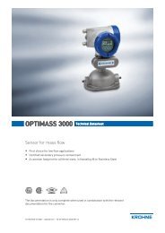
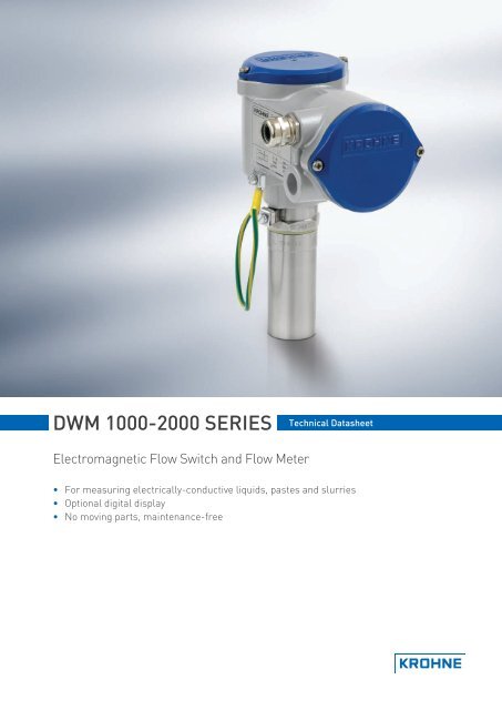
<strong>DWM</strong> <strong>1000</strong>-<strong>2000</strong> <strong>SERIES</strong><strong>Technical</strong> <strong>Datasheet</strong>Electromagnetic Flow Switch and Flow Meter• For measuring electrically-conductive liquids, pastes and slurries• Optional digital display• No moving parts, maintenance-free
nnnnnnnnnnnnnnnnnnnnnnnnnnnnnnnnnnnn <strong>DWM</strong> <strong>1000</strong>-<strong>2000</strong> <strong>SERIES</strong>Variants<strong>DWM</strong> <strong>1000</strong>The <strong>DWM</strong> <strong>1000</strong> flow switch is an insertion-type, twowire system. The switching point is adjustable overa full-scale range of 0.1...9.9 m/s or 0.3...32.5 ft/s.Amplifier relays are also available for a selection ofAC and DC voltages.A welding socket is supplied as standard forwelding the <strong>DWM</strong> <strong>1000</strong> directly onto process pipes.It is suitable for pipe diameters DN50...400. Anoptional spool piece can be used to install theinstrument without a welding operation.<strong>DWM</strong> <strong>2000</strong>The <strong>DWM</strong> <strong>2000</strong> flow meter is an insertion-typeinstrument. Full scale range is a adjustable from1...8 m/s or 3.3...26.2 ft/s.The <strong>DWM</strong> <strong>2000</strong> has an optional liquid crystaldisplay. Other remote display options are available(C95 CI).A welding socket is supplied as standard forwelding the <strong>DWM</strong> <strong>2000</strong> directly onto process pipes.It is suitable for pipe diameters DN50...400. Anoptional spool piece can be used to install theinstrument without a welding operation.www.krohne.com 3
<strong>DWM</strong> <strong>1000</strong>-<strong>2000</strong> <strong>SERIES</strong> nnnnnnnnnnnnnnnnnnnnnnnnnnnnnnnnnnnnnOptionsLCD IndicatorThe <strong>DWM</strong> <strong>2000</strong> D flow meter is equipped with atwo-line, 16-character LCD. It indicates flowvelocity on the first line and flow rate on thesecond. It can also be used to calibrate the<strong>DWM</strong> <strong>2000</strong> onsite.This can be retrofitted to all <strong>DWM</strong> <strong>2000</strong> variants,except those with the IP68 stainless steel housingoption.IP68 stainless steel housingThe IP68 stainless steel housing has been designedfor immersed applications. It is a sealed unit andall calibration is carried out before delivery.<strong>DWM</strong> <strong>1000</strong> and <strong>2000</strong> instruments with the IP68stainless steel housing option can also be orderedwith a long sensor.Long sensorThe <strong>DWM</strong> <strong>1000</strong> L and <strong>2000</strong> L are ideal for flowcontrol in large diameter pipes or open channels.They are a suitable alternative to insertionturbines. The sensor is either 500 mm / 20" or<strong>1000</strong> mm / 40" long: it can be supplied up to 3 m /120" long on request. It has these additionalfeatures:• Security chain• Optional welding socket• Optional isolation valve4www.krohne.com
nnnnnnnnnnnnnnnnnnnnnnnnnnnnnnnnnnnn <strong>DWM</strong> <strong>1000</strong>-<strong>2000</strong> <strong>SERIES</strong>Spooling pieceSpooling pieces are available for pipe diametersDN25...50 or 1...2". These have a standard length of200 mm / 7.9".FT Tuchenhagen connectionAn option developed for hygienic applications.Tuchenhagen VARIVENT ® housings are supplied ondemand with <strong>DWM</strong> <strong>1000</strong> FT and <strong>2000</strong> FTinstruments.www.krohne.com 5
<strong>DWM</strong> <strong>1000</strong>-<strong>2000</strong> <strong>SERIES</strong> nnnnnnnnnnnnnnnnnnnnnnnnnnnnnnnnnnnnn<strong>Technical</strong> dataFunctions<strong>DWM</strong> <strong>1000</strong> <strong>DWM</strong> <strong>2000</strong>Description 2-wire flow switch Flow meter with 4…20 mA outputFunctionUser interfaceFor monitoring flow velocity in pipes or open channelsOptions Flashing LED None; 2-line LCD indicator with 4-buttonkeypadInterface languages - English, French or GermanDisplay units, 1st line - m/sDisplay units, 2nd line (optional) - m³/hMeasurement accuracyRepeatability ±1% of the switching point ±1% of the measured valueAccuracywhen v > 1 m/s or 3.3 ft/s ±5% of the switching point ±5% of the measured value(± 2% if calibrated onsite)when v < 1 m/s or 3.3 ft/s±3 cm/s / ±1.2 in./s±2% of the switching pointReference temperature +20°C ±5°C / +70°F ±10°FReference pressureReference relative humidity 60% ±15%1013 mbar abs. ±20 mbar / 14.69 psig ±0.29 psigFull-scale range 0.1…9.9 m/s /0.3…32.5 ft/s, adjustable thresholdHysteresis 8%, when flow velocity decreases -±3cm/s / ±1.2 in./s±2% of the measured value1, 2, 3, 4, 5, 6, 7, or 8 m/s /3.3, 6.6, 9.9,13.1, 16.4, 19.6, 22.9,or 26.2 ft/s, programmable6www.krohne.com
nnnnnnnnnnnnnnnnnnnnnnnnnnnnnnnnnnnn <strong>DWM</strong> <strong>1000</strong>-<strong>2000</strong> <strong>SERIES</strong>Operating conditionsAmbient temperatureProcess temperaturewithout stainless steel housing(IP68) optionwith stainless steel housing(IP68) optionMax. allowable operatingpressureElectrical conductivityProtection category acc. to EN 60529standard variant IP 66with LCD indicator IP 55with FT option IP 66<strong>DWM</strong> <strong>1000</strong> <strong>DWM</strong> <strong>2000</strong>-25…+60°C / -13…+140°F-25…+150°C / -13…+300°F-25…+60°C / -13…+140°F25 bar / 360 psig≥20 µS/cmwith long sensor option IP 66with stainless steel housing IP 68(IP68) optionElectromagnetic compatibility (EMC),to CE EN 50081-1; EN 50082-289/336/EEC (EMC)72/73/EEC (Low Voltage Directive)Installation conditionsMinimum inlet runMinimum outlet runPipe material10 x nominal diameter, depending on the flow profile5 x nominal diameter, depending on the flow profileElectrically conductive materials, refer to the handbook for other materialswww.krohne.com 7
29-4-2010GAZZETTA UFFICIALE DELLA REPUBBLICA ITALIANA Serie generale - n. 99videosorveglianza e che sia riconducibile a quanto disposto dall’art. 37 del Codice, deveessere preventivamente notificato a questa Autorità.La mancata o incompleta notificazione ai sensi degli artt. 37 e 38 del Codice è punita con lasanzione amministrativa prevista dall’art. 163.3.3. Misure di sicurezza da applicare ai dati personali trattati mediantesistemi di videosorveglianza e soggetti preposti3.3.1. Misure di sicurezzaI dati raccolti mediante sistemi di videosorveglianza devono essere protetti con idonee epreventive misure di sicurezza, riducendo al minimo i rischi di distruzione, di perdita,anche accidentale, di accesso non autorizzato, di trattamento non consentito o nonconforme alle finalità della raccolta, anche in relazione alla trasmissione delle immagini(artt. 31 e ss. del Codice).Devono quindi essere adottate specifiche misure tecniche ed organizzative che consentanoal titolare di verificare l’attività espletata da parte di chi accede alle immagini o controlla isistemi di ripresa (se soggetto distinto dal titolare medesimo, nel caso in cui questo siapersona fisica).E’ inevitabile che -in considerazione dell’ampio spettro di utilizzazione di sistemi divideosorveglianza, anche in relazione ai soggetti e alle finalità perseguite nonché dellavarietà dei sistemi tecnologici utilizzati- le misure minime di sicurezza possano variareanche significativamente. E’ tuttavia necessario che le stesse siano quanto meno rispettosedei principi che seguono:a) in presenza di differenti competenze specificatamente attribuite ai singoli operatoridevono essere configurati diversi livelli di visibilità e trattamento delle immagini (v.punto 3.3.2). Laddove tecnicamente possibile, in base alle caratteristiche dei sistemiutilizzati, i predetti soggetti, designati incaricati o, eventualmente, responsabili deltrattamento, devono essere in possesso di credenziali di autenticazione che permettanodi effettuare, a seconda dei compiti attribuiti ad ognuno, unicamente le operazioni dipropria competenza;b) laddove i sistemi siano configurati per la registrazione e successiva conservazione delleimmagini rilevate, deve essere altresì attentamente limitata la possibilità, per i soggettiabilitati, di visionare non solo in sincronia con la ripresa, ma anche in tempo differito,le immagini registrate e di effettuare sulle medesime operazioni di cancellazione oduplicazione;c) per quanto riguarda il periodo di conservazione delle immagini devono esserepredisposte misure tecniche od organizzative per la cancellazione, anche in formaautomatica, delle registrazioni, allo scadere del termine previsto (v. punto 3.4);d) nel caso di interventi derivanti da esigenze di manutenzione, occorre adottarespecifiche cautele; in particolare, i soggetti preposti alle predette operazioni possonoaccedere alle immagini solo se ciò si renda indispensabile al fine di effettuare eventualiverifiche tecniche ed in presenza dei soggetti dotati di credenziali di autenticazioneabilitanti alla visione delle immagini;— 72 —
nnnnnnnnnnnnnnnnnnnnnnnnnnnnnnnnnnnn <strong>DWM</strong> <strong>1000</strong>-<strong>2000</strong> <strong>SERIES</strong>Power supply<strong>DWM</strong> <strong>1000</strong> <strong>DWM</strong> <strong>2000</strong>Instrument terminal 48…250 VAC or VDC 12 / 24 VDCRelay options for instrument 230 / 110 / 48 VAC; 110 / 48 VDC -terminalPower consumption 200 mA max. 50 mA max.Protective earthing load 1
<strong>DWM</strong> <strong>1000</strong>-<strong>2000</strong> <strong>SERIES</strong> nnnnnnnnnnnnnnnnnnnnnnnnnnnnnnnnnnnnnDimensions and WeightStandard sub-variants1 <strong>DWM</strong> <strong>1000</strong> or <strong>DWM</strong> <strong>2000</strong> with optional welding socket2 <strong>DWM</strong> <strong>2000</strong> D (with LCD indicator) with optional welding socket3 <strong>DWM</strong> <strong>1000</strong> or <strong>DWM</strong> <strong>2000</strong> with spool piece for inline connectionNote:• PG13.5 cable glands are supplied as standard• LCD indicators can be retrofitted to all <strong>DWM</strong> <strong>2000</strong>s with aluminium housings10www.krohne.com
nnnnnnnnnnnnnnnnnnnnnnnnnnnnnnnnnnnn <strong>DWM</strong> <strong>1000</strong>-<strong>2000</strong> <strong>SERIES</strong>Standard sub-variants without spool piece: Dimensions and Weight in mm and kgWithout LCDindicatorWith LCDindicator1 the tolerance is +0/-0.2 mmDimensions [mm]a b c d e f g j k L p160 80 80 Ø28 90 132 G1 95 122 86 Ø391163 86 80 Ø28 90 164 G1 95 122 86 Ø391Weight[kg]1.92.4Standard sub-variants without spool piece: Dimensions and Weight in inches and lbsWithout LCDindicatorWith LCDindicator1 the tolerance is +0/-0.008"Dimensions [inches]a b c d e f g j k L p6.3 3.1 3.1 Ø1.1 3.5 5.2 G1 3.7 4.8 3.4 Ø1.516.4 3.4 3.1 Ø1.1 3.5 6.5 G1 3.7 4.8 3.4 Ø1.51Weight[lbs]4.25.3Standard sub-variants with spool piece: Dimensions and Weight in mm and kgWith spool piece,PN40With spool piece,ANSI 150 lbsWith spool piece,ANSI 300 lbsDimensions [mm]ND a b c k L2 m nWeight[kg]DN25…50 160 80 80 122 200 226 92 8.91…2" 160 80 80 122 200 226 92 8.91…2" 160 80 80 122 200 226 92 8.9Standard sub-variants with spool piece: Dimensions and Weight in inches and lbsWith spool piece,PN40With spool piece,ANSI 150 lbsWith spool piece,ANSI 300 lbsDimensions [inches]ND a b c k L2 m nWeight[lbs]DN25…50 6.3 3.1 3.1 4.8 7.9 8.9 3.6 29.21…2" 6.3 3.1 3.1 4.8 7.9 8.9 3.6 29.21…2" 6.3 3.1 3.1 4.8 7.9 8.9 3.6 29.2www.krohne.com 11
<strong>DWM</strong> <strong>1000</strong>-<strong>2000</strong> <strong>SERIES</strong> nnnnnnnnnnnnnnnnnnnnnnnnnnnnnnnnnnnnnLong sub-variants1 <strong>DWM</strong> <strong>1000</strong> L or <strong>DWM</strong> <strong>2000</strong> L with safety chain, optional G 1½ isolation valve and optional welding socket or NPT 1½ adaptor2 <strong>DWM</strong> <strong>2000</strong> L with LCD indicator, safety chain, optional G 1½ isolation valve and optional welding socket or NPT 1½ adaptorNote:• PG13.5 cable glands are supplied as standard• A safety chain is supplied as standard with <strong>DWM</strong> <strong>1000</strong> L and <strong>DWM</strong> <strong>2000</strong> L instruments• LCD indicators can be retrofitted to all <strong>DWM</strong> <strong>2000</strong>s with aluminium housings12www.krohne.com
nnnnnnnnnnnnnnnnnnnnnnnnnnnnnnnnnnnn <strong>DWM</strong> <strong>1000</strong>-<strong>2000</strong> <strong>SERIES</strong>Dimensions and Weight in mm and kgWithoutindicatorWith LCDindicatorDimensions [mm]a b c d f g i j k L p r s t u v160 80 80 Ø601163 86 80 Ø601Weight[kg]132 2 Ø28 95 122 3 28 16 75 95 60 - 3.6164 4 Ø28 95 122 3 28 16 75 95 60 36 4.11 Tolerance: +0/-0.2 mm2 G1½ or NPT 1½. A screw-on NPT 1½ adaptor is also available for the optional G 1½ isolation valve.3 Standard lengths are 500 or <strong>1000</strong> mm. Up to 3000 mm on request.4 G1½ or NPT 1½. A screw-on NPT 1½ adaptor is also available for the optional G 1½ isolation valve.Dimensions and Weight in inches and lbsWithoutindicatorWith LCDindicatorDimensions [inches]a b c d f g i j k L p r s t u v6.3 3.1 3.1 Ø2.416.4 3.4 3.1 Ø2.41Weight[lbs]5.2 2 Ø1.1 3.7 4.8 3 1.1 0.6 3.0 3.7 2.4 - 7.96.5 4 Ø1.1 3.7 4.8 3 1.1 0.6 3.0 3.7 2.4 1.4 9.01 Tolerance: +0/-0.008"2 G1½ or NPT 1½. A screw-on NPT 1½ adaptor is also available for the optional G 1½ isolation valve.3 Standard lengths are 20 or 40". Up to 120" on request.4 G1½ or NPT 1½. A screw-on NPT 1½ adaptor is also available for the optional G 1½ isolation valve.www.krohne.com 13
<strong>DWM</strong> <strong>1000</strong>-<strong>2000</strong> <strong>SERIES</strong> nnnnnnnnnnnnnnnnnnnnnnnnnnnnnnnnnnnnnIP68 housing sub-variants1 <strong>DWM</strong> <strong>1000</strong> IP68 or <strong>DWM</strong> <strong>2000</strong> IP68 with optional welding socket2 <strong>DWM</strong> <strong>1000</strong> IP68 L or <strong>DWM</strong> <strong>2000</strong> IP68 L with optional G 1½ isolation valve and optional welding socket or NPT 1½ adaptorNote:• For immersed applications• PG13.5 cable glands are supplied as standard• A safety chain is supplied as standard with <strong>DWM</strong> <strong>1000</strong> L and <strong>DWM</strong> <strong>2000</strong> L instruments14www.krohne.com
nnnnnnnnnnnnnnnnnnnnnnnnnnnnnnnnnnnn <strong>DWM</strong> <strong>1000</strong>-<strong>2000</strong> <strong>SERIES</strong>Dimensions and Weight in mm and kgDimensions [mm]Weight [kg]StandardvariantLongvarianta b d e f g i L p r s t u v126 Ø89 Ø391126 Ø89 Ø60290 195 G1 Ø28 86 - - - - - - 5.7- 195 3 Ø28 4 28 16 75 95 60 36 8.41 Tolerance: +0/-0.2 mm2 Tolerance: +0/-0.2 mm3 G1½ or NPT 1½. A screw-on NPT 1½ adaptor is also available for the optional G 1½ isolation valve.4 Standard lengths are 500 or <strong>1000</strong> mm. Up to 3000 mm on request.Dimensions and Weight in inches and lbsStandardvariantLongvariantDimensions [inches]a b d e f g i L p r s t u v5.0 Ø3.5 Ø1.515.0 Ø3.5 Ø2.41Weight [lbs]3.5 7.7 G1 Ø1.1 3.4 - - - - - - 12.6- 7.7 2 Ø1.1 3 1.1 0.6 3.0 3.7 2.4 1.4 18.51 Tolerance: +0/-0.008"2 G1½ or NPT 1½. A screw-on NPT 1½ adaptor is also available for the optional G 1½ isolation valve.3 Standard lengths are 20 or 40". Up to 120" on request.www.krohne.com 15
<strong>DWM</strong> <strong>1000</strong>-<strong>2000</strong> <strong>SERIES</strong> nnnnnnnnnnnnnnnnnnnnnnnnnnnnnnnnnnnnnFT sub-variants1 <strong>DWM</strong> <strong>1000</strong> FT or <strong>DWM</strong> <strong>2000</strong> FT with a Tuchenhagen VARIVENT ® process connection2 <strong>DWM</strong> <strong>2000</strong> FT with an LCD indicator and a Tuchenhagen VARIVENT ® process connectionNote:• PG13.5 cable glands are supplied as standard• LCD indicators can be retrofitted to all <strong>DWM</strong> <strong>2000</strong>s with aluminium housings16www.krohne.com
nnnnnnnnnnnnnnnnnnnnnnnnnnnnnnnnnnnn <strong>DWM</strong> <strong>1000</strong>-<strong>2000</strong> <strong>SERIES</strong>Dimensions and Weight in mm and kgDimensions [mm]Without LCDindicatorWith LCDindicatora b c f j k L Weight [kg]160 80 80 185 95 122 38 2.3163 86 80 185 95 122 38 2.8Dimensions and Weight in inches and lbsDimensions [inches]Without LCDindicatorWith LCDindicatora b c f j k L Weight [lbs]6.3 3.1 3.1 7.3 3.7 4.8 1.5 5.16.4 3.4 3.1 7.3 3.7 4.8 1.5 6.2www.krohne.com 17
<strong>DWM</strong> <strong>1000</strong>-<strong>2000</strong> <strong>SERIES</strong> nnnnnnnnnnnnnnnnnnnnnnnnnnnnnnnnnnnnn$$$18www.krohne.com
nnnnnnnnnnnnnnnnnnnnnnnnnnnnnnnnnnnn <strong>DWM</strong> <strong>1000</strong>-<strong>2000</strong> <strong>SERIES</strong>$$$www.krohne.com 19