Type GH505 DC Magnetic Shoe Brake - 23 - Duke Brakes
Type GH505 DC Magnetic Shoe Brake - 23 - Duke Brakes
Type GH505 DC Magnetic Shoe Brake - 23 - Duke Brakes
- No tags were found...

You also want an ePaper? Increase the reach of your titles
YUMPU automatically turns print PDFs into web optimized ePapers that Google loves.
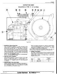
ItemNo.Description Of PartNo.Req.RENEWAL PARTS(Refer to Fig. 2, Page 2)ItemPart No.Description Of PartNo.PUBLICATION NO. 17228No.Req.Part No.18 Angle Bracket ……………………... 2 79-15572-51 Locknut 1½ - 6 ……………………. 1 15-6735/8-11 X 1.25 Hex Head Bolt ......... 4 11-35582 Spring ……………………………… 1 69-1987 195/8 Helical Washer ........................ 4 916-1363Z3 Spring Pin .3125 X 2.25” Long ..... 1 13-3186-13 20 Stop Block ..................................... 2 19-972-6Stop Plate ......................................19-3220-9.093 thickness ...............................4 Pull Rod (includes items 2 & 3) ..... 1 61-1008 21*2 19-3220-11.102 thickness ...............................19-3220-12.105 thickness ...............................5 Locknut ……………………….……. 1 915-1682Z 22 Gasket ........................................... 2 32-467-11Wedge Adj Screw Assembly……... 1 54-11507-46<strong>23</strong> Inner <strong>Shoe</strong> Lever (includes item 7) 1 24-3304-8(includes item 5).…………………..724 Base (includes items 22, 26, 27, 1 17-8047Adjusting Wedge …………….……. 1 54-27648Inner Armature …………………….Sounding Pin ……………………...Sounding Pin Bushing …………….11148-636-413-3485-329-2762-32528, 29) ………………………………<strong>Brake</strong> Wheel (give completenameplate data) ……………………1 …………..9 Pin ……….…….............................. 1 13-1181-16 26 Screw 5/8-11 X .625” Long ........... 4 11-2051-210Outer Armature ……………………Sounding Pin ……………………...Sounding Pin Bushing …………….11148-636-1213-3485-329-2762-327 Lock Bracket ………………………. 4 79-4180-2811 Rubber Guard …………………….. 1 73-1017-6 28 Retainer ......................................... 4 55-154812 Spring Pin .3125 X 1.75” Long 1 13-3186-12 29 Gasket ……………………………… 2 32-467-613Torque Adjusting Screw …………. 1 11-4625-6(includes items 12 & 14) ………….30 Outer <strong>Shoe</strong> Lever …………………. 1 24-3305-41431 <strong>Shoe</strong> Lining (for riveted shoe only 2 48-1818-6Gland ………………………………. 1 49-2201-2Groov-Pin (rivet) …………………... 80 13-476215 Torque Spring …………………….. 1 69-1692 32 Clamp ……………………………… 4 55-103916 Coil (Give No. On Coil) …………... 1 ………… 33 Self-Locking Bolt 5/8-11 X 2.75” … 4 11-3046-417 Self-Locking Screw 5/8”-11 X 1.25 4 11-4642 34 <strong>Shoe</strong> (w/ riveted lining) …………… 2 48-633-4Angle Brkt Bushing (not shown) 4 29-5535-4 35 Spherical Washer .......................... 1 16-1598-536 Hex Jam Nut 1-1/2-6 ……………… 1 915-<strong>23</strong>82Z* Choose the plate thickness which gives the minimum gap between armature item 10, the stop block item 20, and the base item 24.RENEWAL OF BRAKE SHOE LININGS(Linings Fastened with Groov-Pins)1. After removing the old lining and groov-pins,clamp the new lining so it lies closely in the shoe.2. Drill through the lining from the rear of the shoewith no. 13 (.185) drill.3. Counter-bore 9/16” to dimensions shown in thesketch to the right. Bottom of counter-bore to be135° included angle. (number of holes requiredper table below)<strong>Brake</strong> SizeNo. Req’dPer <strong>Shoe</strong>BRAKE LININGS FASTENED WITH GROOV-PINGroov-PinPart No. Hole In Lining Hole in <strong>Shoe</strong> Counter-Bore Lining<strong>23</strong>” 48 13-4762 # 13 (.185”) drill3/16” Ream and 20° Cts’k to.210-.220 DiameterPROCEDURE FOR REMOVAL OF A SHOE(Refer to Fig. 1 page 1)9/16” Diameter DepthPer Above Sketch1. Back off locknut “U” and nut “P” on the pull rod“A”. or loosen locknut “T” and turn screw “C”clockwise to lift the wedge to relieve the pressurebetween the chosen shoe and wheel.2. Remove screws “K” from the shoe beingremoved.3. Slide the shoe out sideways4. Re-assemble new shoe into groove in shoelever. Do not tighten screws at this time.5. Press the shoe against the wheel and tightenscrews “K”.6. Readjust brake.MADE IN U.S.A PAGE 3
PUBLICATION NO. 17228PROCEDURE FOR REMOVAL OF A SHOE LEVER(Refer to Fig. 1, Page 1)1. If removal of the outer shoe lever “N” isrequired, loosen locknut “U” and back off nut“P” until the pull rod “A” may be lifted uparound the pivot in the outer armature “F”.2. Refer to shoe retainer “M”. Both sides of theshoe lever are equipped with a lock bracket,screw, and retainer plate. Bend back tab ofthe lock bracket. Remove screw and retainerplate. When re-installing and after tighteningthe screw, bend the tab of the lock bracketagainst the flat of the screw.3. With the retaining plate removed, slide theouter shoe lever “N” to either side of thebrake.4. To remove the inner shoe lever “L”, loosenlocknut “T” and turn screw “C” clockwise untilthe pressure of the shoe against the wheel isrelieved. Refer to shoe retainer “M”. Bothsides of the shoe lever are equipped with alock bracket, screw, and retainer plate. Bendback tab of the lock bracket. Remove screwand retainer plate. When re-installing andafter tightening the screw, bend the tab of thelock bracket against the flat of the screw.5. With the retaining plate removed, slide theouter shoe lever “L” to either side of thebrake.REPLACEMENT OF A COIL(Refer to Fig. 1, Page 1)1. Turn torque adjuster “G” counter clockwiseuntil the torque spring is loose.2. Disconnect thee pull rod end from the outerarmature “F”.3. Remove screws “H” from base.4. Lift the outer armature “F” out of the pocketin the base and pull outward.5. Remove the screws “J” used to attached thecoil to the base pedestal and slide coil frombase pedestal.6. Set the new coil on the pedestal and installmounting screws “J”. Do not tighten at thistime.7. Set the armature “F” back into position. Thespring gland of the torque adjuster must becentered in the hole of the inner armature”D”. Assemble angle bracket and screws “H”and “R” with screws hand tight only.8. Attach pull rod “A” to armature “F”.9. Pull armatures “F” and “D” togethermagnetically or by using a clamp. Tightenscrews “H” and the base such that aclearance of 0.25 ± 0.015 will be maintainedbetween the armature “F” and bracket “S”.The clearance should be uniform. Removeclamp (if used).10. Adjust the torque spring and shoe positionsas described in the installation instructions.PROCEDURE FOR RE-ADJUSTMENT FOR LINING WEAR(Refer to Fig. 1, Page 1)Periodic checks should be made on theinstallation and when the sounding pins depressmore than 1/64” below surface, adjustmentsshould be made to compensate for normal liningwear. This check and the adjustments should bemade when the wheel is at normal operatingtemperature to allow for thermal expansion of thewheel. Re-inspect after several operations.1. Loosen the locknut “U” and tighten nut“P” on the outer end of pull rod “A” untilthe sounding pin in the outer armatureis flush with the surface when it ispressed.2. Loosen locknut “T”. Turn screw “C”counter-clockwise to move the wedgedownward until the inner armaturesounding pin is flush when it is pressedinward.3. Tighten locknuts “U” and “T”.It is recommended the brake shoe linings bereplaced when the lining thickness at thecenter of the shoe has decreased to .125”for riveted construction and .062 for bondedconstruction. Use genuine OEM liningmaterial only to insure brake maintainsrated torque.(See paragraph 14, Page 2)MADE IN U.S.A PAGE 4