5193SD, 5193SDT Addressable Photoelectric Smoke ... - Syscom
5193SD, 5193SDT Addressable Photoelectric Smoke ... - Syscom
5193SD, 5193SDT Addressable Photoelectric Smoke ... - Syscom
You also want an ePaper? Increase the reach of your titles
YUMPU automatically turns print PDFs into web optimized ePapers that Google loves.
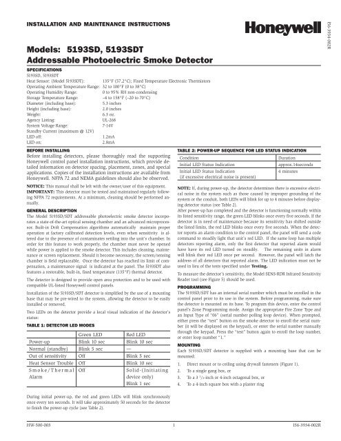
INSTALLATION AND MAINTENANCE INSTRUCTIONSModels: <strong>5193SD</strong>, <strong>5193SD</strong>T<strong>Addressable</strong> <strong>Photoelectric</strong> <strong>Smoke</strong> DetectorSPECIFICATIONS<strong>5193SD</strong>, <strong>5193SD</strong>THeat Sensor: (Model <strong>5193SD</strong>T): 135°F (57.2°C); Fixed Temperature Electronic ThermistorsOperating Ambient Temperature Range: 32 to 100°F (0 to 38°C)Operating Humidity Range:0 to 95% RH non-condensingStorage Temperature Range:–4 to 158°F (–20 to 70°C)Diameter (including base):5.3 inchesHeight (including base):2.0 inchesWeight:6.3 oz.Agency Listing:UL-268System Voltage Range: 7-14VStandby Current (maximum @ 12V)LED off:1.2mALED on:2.8mABEFORE INSTALLINGBefore installing detectors, please thoroughly read the supportingHoneywell control panel installation instructions, which provide detailedinformation on detector spacing, placement, zones, and specialapplications. Copies of the installation instructions are available fromHoneywell. NFPA 72 and NEMA guidelines should also be observed.NOTICE: This manual shall be left with the owner/user of this equipment.IMPORTANT: This detector must be tested and maintained regularly followingNFPA 72 requirements. At a minimum, cleaning should be performed annually.GENERAL DESCRIPTIONThe Model <strong>5193SD</strong>/SDT addressable photoelectric smoke detector incorporatesa state-of-the-art optical sensing chamber and an advanced microprocessor.Built-in Drift Compensation algorithms automatically maintain properoperation at factory calibrated detection levels, even when sensitivity is altereddue to the presence of contaminates settling into the unit’s chamber. Inorder for this feature to work properly, the chamber must never be openedwhile power is applied to the smoke detector. This includes cleaning, maintenanceor screen replacement. Should it become necessary, the screen/sensingchamber is field replaceable. Once the detector has reached its limit of compensation,a maintenance signal is indicated at the panel. The <strong>5193SD</strong>T alsofeatures a restorable, built-in, fixed temperature (135°F) thermal detector.The detector is designed to provide open area protection and to be used withcompatible UL-listed Honeywell control panels.Installation of the <strong>5193SD</strong>/SDT detector is simplified by the use of a mountingbase that may be pre-wired to the system, allowing the detector to be easilyinstalled or removed.Two LEDs on the detector provide a local visual indication of the detector’sstatus:TABLE 1: DETECTOR LED MODESGreen LED Red LEDPower-up Blink 10 sec Blink 10 secNormal (standby) Blink 5 sec —Out of sensitivity Off Blink 5 secHeat Sensor Trouble Off Blink 10 secS m o k e / T h e r m a lAlarmOffSolid-(Initiatingdevice only)Blink 1 secTABLE 2: POWER-UP SEQUENCE FOR LED STATUS INDICATIONConditionInitial LED Status IndicationInitial LED Status Indication(if excessive electrical noise is present)Durationapprox.14seconds4 minutesNOTE: If, during power-up, the detector determines there is excessive electricalnoise in the system such as those caused by improper grounding of thesystem or the conduit, both LEDs will blink for up to 4 minutes before displayingdetector status (see Table 2).After power-up has completed and the detector is functioning normally withinits listed sensitivity range, the green LED blinks once every five seconds. If thedetector is in need of maintenance because its sensitivity has shifted outsidethe listed limits, the red LED blinks once every five seconds. When the detectorreports an alarm condition to the control panel, the panel will send a codecommand to steadily light that unit’s red LED. If the same loop has multipledetectors reporting alarm, only the first detector that reported alarm wouldhave have its red LED turned on steadily. The remaining units in alarmwill blink their red LED once per second. However, the panel will latch theaddress of all detectors that reported alarm. The LED indication must not beused in lieu of the tests specified under Testing.To measure the detector’s sensitivity, the Model SENS-RDR Infrared SensitivityReader tool (see Figure 5) should be used.PROGRAMMINGThe <strong>5193SD</strong>/SDT has an internal serial number which must be enrolled in thecontrol panel prior to its use in the system. Before programming, make surethe detector is mounted on its base. To program this device, enter the controlpanel’s Zone Programming mode. Assign the appropriate Fire Zone Type andan Input Type of “06” (serial number polling loop device). When prompted,either press the “test” button on the smoke detector to enroll the serial number(it will be displayed on the keypad), or enter the serial number manuallythrough the keypad. Press the “test” button again to enroll the loop number,or enter loop number “1.”MOUNTINGEach <strong>5193SD</strong>/SDT detector is supplied with a mounting base that can bemounted:1. Direct mount or to ceiling using drywall fasteners (Figure 1).2. To a single gang box, or3. To a 3 1 /2-inch or 4-inch octagonal box, or4. To a 4-inch square box with a plaster ringI56-3934-002RDuring initial power-up, the red and green LEDs will blink synchronouslyonce every ten seconds. It will take approximately 50 seconds for the detectorto finish the power-up cycle (see Table 2).HW-500-003 1 I56-3934-002R
FIGURE 1: MOUNTING OF DETECTORINSTALLATIONWARNINGRemove power from alarm control unit or initiating device circuits before installingdetectors.S0121-00TAMPER-RESISTANT FEATUREThe <strong>5193SD</strong>/SDT detector includes a tamper-resistant feature that preventsremoval from the mounting base without the use of a tool. To engage the tamper-resistantfeature, cut the small plastic tab located on the mounting base(Figure 2), and then install the detector. To remove the detector from the baseonce it has been made tamper resistant, use a small screwdriver to depress thesquare tamper release tab, located on the skirt of the mounting base, and turnthe detector counterclockwise.FIGURE 2: TAMPER-RESISTANT FEATUREDIRECT MOUNTHOLESNOTE: To install units so that corresponding LEDs are lined up, refer to the“Green LED” indicator on the base.1. Wire the mounting base screw terminals per Figure 3.2. Place detector on the base and rotate clockwise. The detector will dropinto the base and lock into place with a “click”.3. After all detectors have been installed, apply power to the alarm controlunit or initiating device circuits.4. Test each detector as described in Testing.5. Reset all the detectors at the system control panel.6. Notify the proper authorities that the system is in operation.TESTINGDetectors must be tested after installation and following maintenance.NOTE: Before testing, notify the proper authorities that maintenance is beingperformed and the system will be temporarily out of service. Disable the zoneor system undergoing maintenance to prevent any unwanted alarms.Ensure proper wiring and power is applied. After power up, allow 50seconds for the detector to stabilize before testing.TEST <strong>5193SD</strong>/SDT DETECTOR AS FOLLOWS:A.Test SwitchFIGURE 4: RECESSED TEST SWITCH OPENING AND SENS-RDR POSITIONPOSITION SENS-RDRAT AN ANGLE ON THEOVAL AREA OR AT THECHAMBER OPENINGBY THE WORD “PAINT”TAMPERRELEASE TABSNAP OFF TABFOR TAMPER LOCKS0226-00WIRING INSTALLATION GUIDELINESAll wiring must be installed in compliance with the National Electrical Code,applicable state and local codes, and any special requirements of the localAuthority Having Jurisdiction.Proper wire gauges should be used. The conductors used to connect smokedetectors to the alarm control panel and accessory devices should be colorcodedto reduce the likelihood of wiring errors. Improper connections canprevent a system from responding properly in the event of a fire.The screw terminals in the mounting base will accept 14–22 gauge wire. Forbest system performance, all wiring should be installed in separate groundedconduit; do not mix fire alarm system wiring in the same conduit as any otherelectrical wiring. Twisted pair may be used to provide additional protectionagainst extraneous electrical interference.Wire connections are made by stripping approximately 1 /4-inch of insulationfrom the end of the feed wire, inserting it into the proper base terminal, andtightening the screw to secure the wire in place.LEDRECESSED TEST SWITCHFIGURE 5: POSITION OF READERORPUSH RECESSEDSWITCH WITH A0.18″ MAX.DIAMETER TOOLS0135-01S0227-00WIRING DIAGRAMFIGURE 3: WIRING DIAGRAM, <strong>5193SD</strong>/SDT+–CONTROLPANEL+–+–S0133-011. An opening for the recessed test switch is located on the detector housing(See Figure 4).2. Insert a small screwdriver or allen wrench (0.18˝ max.) into the testswitch opening; push and hold.3. If the detector is within the listed sensitivity limits, the detector’s redLED should light within five seconds. An alarm should be annunciated atthe system’s control or console within 5 seconds.B. <strong>Smoke</strong> Entry TestCanned aerosol simulated smoke (canned smoke agent) may be used forsmoke entry testing of the smoke detector. Tested and approved aerosolsmoke products are the <strong>Smoke</strong> Detector Tester model 25S available fromHome Safeguard Industries and Chekkit <strong>Smoke</strong> Detector Tester modelsCHEK02 and CHEK06 available from SDi. When used properly, thecanned smoke agent will cause the smoke detector to go into alarm.HW-500-003 2 I56-3934-002R
Refer to the manufacturer’s published instructions for proper use of thecanned smoke agent.C. Direct Heat Method (<strong>5193SD</strong>T only)Using a 1000-1500 watt hair dryer, direct the heat toward either of thethermistors. Hold the heat source about 12 inches from the detector toavoid damage to the plastic.D. Auto-maintenance Feature: Test detector alarm operation from thecontrol panel if applicable (refer to control panel test procedure).If a detector fails any of the above test methods, its wiring should be checkedand it should be cleaned as outlined in the Maintenance section. If thedetector still fails, it should be replaced.Notify the proper authorities when the system is back in service.MaintenanceNOTE: Before performing maintenance on the detector, notify the properauthorities that maintenance is being performed and the system will be temporarilyout of service. Disable the zone or system undergoing maintenanceto prevent any unwanted alarms. Power must be removed from the panelbefore performing maintenance of any kind.1. Remove the detector cover by turning counterclockwise.2. Vacuum the cover or use canned air to remove any dust or debris.3. Remove the top half of the screen/sensing chamber by lifting straight up(Figure 6).4. Vacuum or use canned air to remove any dust or particles that are presenton both chamber halves.5. Replace the top half of the screen/sensing chamber by aligning the arrowon the screen/sensing chamber with the arrow on the housing. Pressdown firmly until the screen/sensing chamber is fully seated.6. Replace the detector cover by placing it over the screen/sensing chamberand turning it clockwise until it snaps into place.7. Reinstall the detector and test. (See the Testing section.)8. Notify the proper authorities when the system is back in service.FIGURE 6: REMOVING/REPLACING SCREEN/SENSING CHAMBERREMOVABLEDETECTORCOVERSCREEN/SENSINGCHAMBER(TOP HALF)DETECTORHOUSING S0136-00CAUTION<strong>Smoke</strong> detectors are not to be used with detector guards unless the combinationhas been evaluated and found suitable for that purpose.Do NOT Install Detectors in the Following Areas: In or near areas where particles of combustion are normally presentsuch as kitchens; in garages (vehicle exhaust); near furnaces, hot waterheaters, or gas space heaters.In very cold or very hot areas.In wet or excessively humid areas, or next to bathrooms with showers.In dusty, dirty, or insect-infested areas. Near fresh air inlets or returns or excessively drafty areas. Air conditioners,heaters, fans, and fresh air intakes and returns can drive smokeaway from the detector.Consult NFPA 72, the local Authority Having Jurisdiction (AHJ), and/or applicablecodes for specific information regarding the spacing and placementof smoke detectors.CAUTIONDust covers are an effective way to limit the entry of dust into the smoke detectorsensing chamber. However, they may not completely prevent airbornedust particles from entering the detector. Therefore, Honeywell recommendsthe removal of detectors before beginning construction or other dust producingactivity. When returning the system to service, be sure to remove the dustcovers from any detectors that were left in place during construction.For the latest warranty information, please go to: www.security.honeywell.com/hsc/resources/waPlease refer to insert for the Limitations of Fire Alarm SystemsFCC STATEMENTThis device complies with part 15 of the FCC Rules. Operation is subject to the following two conditions: (1) This device may not cause harmful interference, and (2) this device mustaccept any interference received, including interference that may cause undesired operation.Note: This equipment has been tested and found to comply with the limits for a Class B digital device, pursuant to Part 15 of the FCC Rules. These limits are designed to providereasonable protection against harmful interference in a residential installation. This equipment generates, uses and can radiate radio frequency energy and, if not installed and usedin accordance with the instructions, may cause harmful interference to radio communications. However, there is no guarantee that interference will not occur in a particular installation.If this equipment does cause harmful interference to radio or television reception, which can be determined by turning the equipment off and on, the user is encouraged totry to correct the interference by one or more of the following measures:– Reorient or relocate the receiving antenna.– Increase the separation between the equipment and receiver.– Connect the equipment into an outlet on a circuit different from that to which the receiver is connected.– Consult the dealer or an experienced radio/TV technician for help.HW-500-003 3 I56-3934-002R
2 Corporate Center Drive, Melville, NY 11747Copyright © 2008 Honeywell International Inc.www.honeywell.com/securityHW-500-003 4 I56-3934-002R©2008 Honeywell


