Challenges of Megapixel Camera Module Assembly and Test
Challenges of Megapixel Camera Module Assembly and Test
Challenges of Megapixel Camera Module Assembly and Test
- No tags were found...

You also want an ePaper? Increase the reach of your titles
YUMPU automatically turns print PDFs into web optimized ePapers that Google loves.
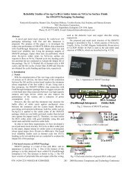
<strong>Challenges</strong> <strong>of</strong> <strong>Megapixel</strong> <strong>Camera</strong> <strong>Module</strong> <strong>Assembly</strong> <strong>and</strong> <strong>Test</strong>Asif Chowdhury 1 , Robert Darveaux 1 , Jay Tome 1 , Ron Schoonejongen 1 , Mitch Reifel 1 , Archie De Guzman 1 , Sung Soon Park 2 ,Yong Woo Kim 2 , Hyung Wook Kim 2 ,1 Amkor Technology, Inc.1900 S. Price Rd.Ch<strong>and</strong>ler, AZ 85236achow@amkor.com480-821-2408 x59492 Amkor Technology KoreaKoreaAbstractDriven by the market growth <strong>of</strong> mobile phones withcamera, production <strong>of</strong> image sensor devices has increaseddramatically in recent years. From 2004 an increasingnumber <strong>of</strong> these mobile phones contain megapixel cameras.The packaging <strong>of</strong> an image sensor in a camera modulepresents several unique engineering challenges. <strong>Megapixel</strong>camera module assembly poses further challenges due tomore stringent particle control criteria. For particle control,special attention has to be given on facilities control,equipment <strong>and</strong> material selection, process flow, disciplineamong line personnel <strong>and</strong> continuous particle reductioneffort. Other material, process <strong>and</strong> equipment selectioncriteria for megapixel module are also discussed. <strong>Test</strong> formegapixel camera module also has its own challenges. Thispaper discusses these challenges <strong>and</strong> methods to meet them.Introduction<strong>Megapixel</strong> image sensors are defined as image sensorswith more than a million individual sensors or pixels. Table1 shows different image sensor display formats. SXGA <strong>and</strong>UXGA are examples <strong>of</strong> megapixel sensors. Some examples<strong>of</strong> megapixel camera modules are shown in Figure 1.Figure 1. Examples <strong>of</strong> megapixel camera moduleImage sensor devices are used in various applicationssuch as surveillance, digital still cameras, PC cameras,medical instruments, bar code readers, PDAs, Toys,automotive <strong>and</strong> mobile phones. <strong>Megapixel</strong> image sensorsare primarily used in digital still cameras but becomingwidely adopted in mobile phones as well. Today digital stillcameras primarily uses image sensors with 3 megapixel orgreater. For mobile phones the most common format todayDesignatorNamePixel ArrayNumber <strong>of</strong> PixelsCIFCommon Intermediate Format352 x 288101,376VGAVideo Graphics Array640 x 480307,200SVGASuper Video Graphics Array800 x 600480,000XGAExtended Graphics Array1024 x 768786,432SXGASuper Extended Graphics Array(or 1.3 Mega Pixel)1280 x 10241,310,720CUXGAUltra Extended Graphics Array(or 2 Mega Pixel)1600 x 12001,920,000Table 1. Common display formats0-7803-8906-9/05/$20.00 ©2005 IEEE 1390 2005 Electronic Components <strong>and</strong> Technology Conference
To keep device sizes relatively small, the pixel sizes aresmaller for megapixel sensors as shown in Figure 4.Currently most megapixel CMOS image sensors have pixelsizes ranging from 3.0 micron to 3.5 micron whilemegapixel CCD sensors have pixel sizes in theneighborhood <strong>of</strong> 2.8 microns. The maximum allowableparticle size on a die is typically equal to one pixel.Hence, for megapixel camera module assembly, particlecontrol strategies must improve.%9080706050403020100Particle on die Particle on glass OthersFigure 5. Defect pareto <strong>of</strong> a 1.3 megapixel camera module.There are numerous sources for particles in theassembly line. Particles can be generated due to poorfacilities control, from material selected for assembly, fromequipment, inadequate cleaning steps during process flow,too many people in the line, etc. Figure 6 shows someexamples <strong>of</strong> particle on image sensor die. Continuousparticle reduction must become a st<strong>and</strong>ard practice byassembly engineers. The next few sections discuss each <strong>of</strong>these in detail from the viewpoint <strong>of</strong> particle reductioneffort. They also cover additional criteria for each sectionwhich are required for megapixel camera module assembly.Facilities ControlTable 3 shows clean room requirement by assembly processstep. The portion <strong>of</strong> the assembly process where the die isexposed is most sensitive to particle. Until the module isencased with the lens system, assembly is typically done inclass 100 environment. Focus <strong>and</strong> barrel lock isrecommended to be done in class 1000 environment whileremainder <strong>of</strong> the assembly process can be done in class100K. The actual clean room particle count must bechecked on a regular interval <strong>and</strong> at strategic places withinthe clean room. For example particle detector should beplaced close to the die attach <strong>and</strong> wire bond process areawhere the die is exposed to the environment. This willprovide data on actual particle control level at those criticalprocess areas. Figure 7 shows a class 100 clean room withvarious particle check point strategically selected based onprocess location. Table 4 shows the actual particle count inthose locations.ProcessClean Room ClassWafer / Glass MountWafer De-tapeWafer / Glass SawDie AttachDie Attach CureWire Bond100Glass AttachGlass Attach CureMount AttachMount Attach CureBarrel InsertBackgrind 1,000FocusBarrel Lock10,000Image <strong>Test</strong>Screen PrintPick <strong>and</strong> PlaceReflow100,000Laser MarkSingulationFlex AttachTable 3. Typical facilities requirementFigure 6. Examples <strong>of</strong> particle defects on image sensor die.The environment inside all equipment should bemonitored <strong>and</strong> steps should be taken for particle reduction.It is possible that while the clean room particle count iswell under control, the particles inside some <strong>of</strong> theseequipment are outside the spec <strong>of</strong> class 100 clean room.Proper airflow inside the equipment is key in reducingparticles. Keeping covers <strong>of</strong> the equipment open or takingthem <strong>of</strong>f completely can help reduce particle level insidethe machines. Figure 8 shows a picture <strong>of</strong> assemblyequipment in operation with the cover open.<strong>Assembly</strong> line layout is also another area where specialattention should be given. Smooth laminar airflow insidethe clean room is important in reducing particle count. Forexample adequate space between equipments, workbenches13922005 Electronic Components <strong>and</strong> Technology Conference
Air shower#6#5#4Pass BoxAir lockMount attach#7Wafer sawDie attachWire Bond#1 #2 #3#Particle check pointsFigure 7. Example <strong>of</strong> strategic locations for particle check point inside class 100 clean roomOver 0.3 0.3 umum(Reference)Over 0.5 0.5 umumPoint 1 4 3Point 2 0 0Point 3 11 8Point 4 9 2Point 5 22 16Point 6 4 3Point 7 0 0Criteria(0.5um base)100 classTable 4. Actual particle count data at each <strong>of</strong> the particle check points shown in Figure 7.a) All moving parts should be away from the actualexposed die area so that particle generated doesnot l<strong>and</strong> on die surface.b) Equipments with its own de-ionized airflowsystem will help reduce particle.c) Incoming air should come through a filtrationsystem ensure clean air coming in.d) Substrate strip indexing should be done on rollersinstead <strong>of</strong> on rails to reduce friction whichgenerates particle.Figure 8. Equipment shown with cover open to allowimproved airflow.<strong>and</strong> shelves must be allowed. A camera module assemblyfloor equipment layout will look sparse compared to that <strong>of</strong>a st<strong>and</strong>ard packaging assembly floor. All workbenches <strong>and</strong>shelves should have adequate ventilation in the form <strong>of</strong>perforation to allow airflow.Equipment SelectionEquipment material <strong>and</strong> design can inherently generateparticles during operation. All h<strong>and</strong>ling area <strong>and</strong> movingparts <strong>of</strong> the equipment should be made such that particlegeneration due to friction is reduced both from a design <strong>and</strong>material selection view point. Examples are given below.In the last two years, a few <strong>of</strong> the well known assemblyequipment suppliers have come up with equipmentspecifically for image sensor assembly. These equipmentinherently generate lesser particle by.<strong>Megapixel</strong> module assembly may require equipmentwith tighter process control specifications. For example,megapixel modules require a tighter optical center to sensorcenter alignment. The current requirement is +/-50 micronsto +/-75 microns for VGA designs. The requirement formegapixel design is +/-25 micron to +/-50 microns, whichrequires advanced assembly equipment as well as tighterprocess control.13932005 Electronic Components <strong>and</strong> Technology Conference
Materials SelectionSeveral <strong>of</strong> the packaging materials used in cameramodules are st<strong>and</strong>ard. Among the st<strong>and</strong>ard materials aresilicon die, gold wire, laminate substrate, ceramic substrate,flex circuit, passive components, <strong>and</strong> connectors.However, there are several materials which are somewhatunique to camera modules when compared to other ICadhesives, mount, lens barrel, lens elements, <strong>and</strong> IR glassfilter. The detail material properties <strong>and</strong> selection criteriahave been discussed in the earlier paper published inSMTA [2]. A general discussion is provided below onsome <strong>of</strong> the unique material selection criteria especiallywith respect the issue <strong>of</strong> particle contamination.In case <strong>of</strong> adhesives, out-gassing properties areimportant in terms <strong>of</strong> potential cause <strong>of</strong> contamination.Adhesives with higher out-gassing may contaminate thesensor surface or the IR glass during the cure process.Table 5 shows comparisons <strong>of</strong> adhesives materials for lensbarrel, mount <strong>and</strong> lens attach in terms <strong>of</strong> their cureconditions <strong>and</strong> out gassing properties.For the mount <strong>and</strong> the lens barrel, the common plasticmaterials used are Liquid Crystal Polymer (LCP),Polyphenelyene Sulfide (PPS), Polyphenelyene Oxide(PPO) <strong>and</strong> Polycarbonate/Acrylonitrile Butadiene Styrene(PC/ABS). Part <strong>of</strong> the process is to screw the lens barrelinto the mount. For fixed focus modules the lens barrel isscrewed or unscrewed during the focus test depending onthe test methodology. Choosing the right materialcombination between the mount <strong>and</strong> the lens barrel willreduce particle generation during this barrel insertion <strong>and</strong>focus test process. Another key criteria for selecting theright material for mount <strong>and</strong> lens barrel is its ability towithst<strong>and</strong> the adhesive cure temperature. Temperatureunder deflection under a certain load for each <strong>of</strong> thesematerials is shown in Table 6. It is seen that LCP <strong>and</strong> PPShave relatively higher temperature <strong>of</strong> deflection comparedto that <strong>of</strong> PPO <strong>and</strong> PC/ABS. For this reason, LCP <strong>and</strong> PPSare being widely used for mount <strong>and</strong> lens barrel. A test wasdone on mount <strong>and</strong> barrel each made <strong>of</strong> LCP <strong>and</strong> PPSmaterial. Simulated focus operation was performed on each<strong>of</strong> these mounts <strong>and</strong> barrels <strong>and</strong> then the IR glass waschecked for particles. It was observed that LCP materialproduced no particle on the IR glass while PPS produced asmall percentage <strong>of</strong> particles. Table 7 <strong>and</strong> Figure 9summarize the results.Similar tests should be done before choosing lenselement material as well. Examples <strong>of</strong> lens elementc<strong>and</strong>idates with their processability <strong>and</strong> maximum servicetemperature are shown in Table 8. Among the plasticmaterials, Zeonex is being widely used for its goodworkability <strong>and</strong> relatively high service temperature.In the case <strong>of</strong> IR filter, particles can be generated fromthe IR coat material. Depending on the coat material <strong>and</strong>process, it may produce flakes during process conditions<strong>and</strong> also during reliability test conditions. IR filter fromeach supplier should be tested under the conditionscorresponding to the actual process <strong>and</strong> reliability testconditions to ensure integrity <strong>of</strong> the coat material.Figure 9. Particle related performance for PPS (left picture)<strong>and</strong> LCP (right) as materials for mount <strong>and</strong> barrel.<strong>Assembly</strong> ProcessThe assembly process flow for a camera module isshown in Figure 10. The process is broken into 5 separateflows for wafer, substrate, mount, flex circuit, <strong>and</strong> module.Details <strong>of</strong> camera module process flow have been describedin the paper published in 2004 SMTA [2]. For fixed focusmegapixel camera module the process flow is no different.For auto focus modules the focus <strong>and</strong> lock is obviously notrequired.Careful consideration must be given to cleaning <strong>and</strong>inspection steps within the process flow. All jigs, fixtures,carrier frames, <strong>and</strong> trays must be cleaned prior to use in theclass 100 clean room environment. Use <strong>of</strong> ultrasonic wetcleaning process is common. Among the 5 separate flowsshown in figure 10, flows for wafer, substrate <strong>and</strong> mountare most critical from a particle related defect st<strong>and</strong> point.This is due the fact that the sensor die is exposed duringthese process steps. These sub-processes are also done inclass 100 clean room environment except for the mark <strong>and</strong>singulation process.For the wafer flow, particles can be generated duringbackgrinding process from the backgrinding tape that isattached on the top surface <strong>of</strong> the die. St<strong>and</strong>ardbackgrinding tape can be used if the wafer goes through awet cleaning process before die attach. The st<strong>and</strong>ard wetcleaning during the saw process is adequate. Si particlescan be a major source <strong>of</strong> particle contamination during thewafer saw process. The st<strong>and</strong>ard wet cleaning during thesaw process may not be adequate for removing Si dust.Two steps can be taken to reduce Si partcile contaminationfrom the saw process. First, the saw process must beoptimized to reduce Si dust accumulation on the wafer. Forexample it has been observed that a two pass saw showsless Si dust related contamination vs. st<strong>and</strong>ard one pass sawprocess. Secondly, a separate wet cleaning process afterwafer saw can further reduce any Si particle contamination.Sawn wafers should be inspected to ensure cleanlinessbefore die attach process.As mentioned in the material section, use <strong>of</strong> laminatesubstrate for camera module is increasing. These substratesmust be cleaned using a wet ultrasonic cleaning process13952005 Electronic Components <strong>and</strong> Technology Conference
Wafer FlowWafer MountBackgrindDe-tapeWafer MountWafer SawWafer CleanInspectionFlex Circuit FlowFlex Circuit FlowScreen PrintPick & PlaceReflowSingulateSubstrate FlowSubstrate CleanDie AttachCureDry/wet CleanWire BondDry/wet CleanInspectionMount AttachCleanInspectionCureBarrel InsertLaser MarkSingulate<strong>Module</strong> FlowImage <strong>Test</strong>Functional <strong>Test</strong>FocusBarrel LockFlex AttachO/S <strong>Test</strong>Pack / ShipFigure 10. Typical process flowMount FlowGlass MountGlass SawDry/wet CleanGlass AttachCureDry/wet CleanInspectionbefore die attach. After die attach process the units shouldbe cleaned again. Dry cleaning can be done with ionizedair-blow <strong>and</strong> vacuum pull on each sensor attached tosubstrate. This should be done with the substrate inverted(die down configuration) so that particles will fall <strong>of</strong>f easily.Fig 11 shows a semi-auto dry cleaning equipment usedafter die attach process.Wet cleaning is usually done in an inert environmentusing ultrasonics. Similar cleaning processing should berepeated after the wirebond process as well. On the mountFigure 11. Semi-auto dry cleaning equipment usingdeionized airblow <strong>and</strong> vacuum.1396flow, the IR glass saw process should use a similar cleaningprocess as the wafer saw process. After the IR glass isattached to the mount, the mount sub-assembly is attachedto the substrate sub-assembly which has the sensor dieattached <strong>and</strong> wirebonded. Before the mount attach, themount should also be cleaned <strong>and</strong> inspected. Wet cleaningafter wirebond <strong>and</strong> before mount attach can significantlyreduce particle <strong>and</strong> improve yield.The remainder <strong>of</strong> the module flow <strong>and</strong> flex attach flow isdone in class 100K room. At this point the camera moduleis much less susceptible to particle defect as sensor die <strong>and</strong>the IR filter are already encased.Cleaning frequency <strong>and</strong> methodology <strong>of</strong> equipment inclean room should be optimized. For example if adhesivecure ovens are not cleaned regularly, they can be a largesource <strong>of</strong> particle contamination.Process flow shown in Figure 10 has many inspection stepsto ensure module cleanliness. As process conditions areimproved (proven by higher assembly yield), some <strong>of</strong> theinspection steps can be eliminated or reduced to a samplingbasis.The listed processes all have specific requirements thatimpact the size <strong>and</strong> / or optical performance <strong>of</strong> the cameramodule. Some <strong>of</strong> these requirements exceed currentmanufacturer’s st<strong>and</strong>ard capability. Hence, advanceddevelopment with latest state-<strong>of</strong>-the-art equipment isrequired. Some <strong>of</strong> the critical process capabilityrequirements are shown in Table 9.Process Attribute Requirementwafer thickness 150µmBackgrindtotal thicknessvariation< 10µmdamage to microlenson diezerox,y placement +/- 25µmDieAttachdie tilt +/- 0.2 degreesoutgassingzeroWireBondmin die / mount space 300µmx,y placement +/- 50µmMountAttach overall optical tilt +/- 0.5 degreesoutgassingzeroFlexAttachMax lens temperature 85CTable 9. Typical process capability.Tilt control is critical for megapixel modules. Most <strong>of</strong>the digital still cameras <strong>and</strong> digital SLR cameras have roomfor self-alignment <strong>and</strong> tilt adjusting capability. <strong>Camera</strong>modules in cell phones do not have the room to do this.Whereas VGA modules require about
educe tilt is by changing material from paste type to filmtype. Tape has better inherent tilt performance compared tothat <strong>of</strong> paste. Table 10 lists comparison data <strong>of</strong> a 8mm x8mm die tilt for film <strong>and</strong> paste die attach materials. Itshows a magnitude <strong>of</strong> tilt improvement for film adhesivematerial. However tilt performance using paste die attach iswell within the spec limit <strong>of</strong>
BeforeIR FilterIR FilterTape.Ejector Pin.AfterFigure 13. Routing area <strong>of</strong> laminate substrate canpotentially generate particles.IR FilterIR FilterTape.Ejector Pin.Figure 16a. Tape is stretched to ensure gap between IRfilters.Around 2.5milFigure 14. Ultrasonic cleaning equipment for laminatesubstrates.Figure 16b. Resultant gap <strong>of</strong> 2.5 mils between adjacent IRglass after tape stretch.Figure 15. Magazine h<strong>and</strong>ling was changed from vertical tohorizontal for improving particle on die.sheets are mounted on to saw tape <strong>and</strong> then sawn intoindividual sizes. Then the sawn IR filters are attached intothe mount or lens holder. It was observed that even thoughthe glass piece parts were completely sawn, they werestill touching the adjacent IR glass piece parts <strong>and</strong> weregenerating particles during the pick-up operation. Thecorrective action was to exp<strong>and</strong> the tape after the sawoperation to ensure gap between adjacent IR glass filters.This is illustrated in Figures 16a <strong>and</strong> 16b. A second steptaken was to reverse the IR glass attach (on mount)sequence as shown in figure 17. The purpose is to ensurethat no particle falls on the IR glass that is already attached.1398Figure 17. IR glass attach sequence was reversed to reducethe potential <strong>of</strong> particle on die.To reduce particle caused by sticky tape, 2 steps weretaken as follows.2005 Electronic Components <strong>and</strong> Technology Conference
<strong>and</strong> processing speed will be necessary to keep the test timeshort, especially for very high megapixelResolutionPixel ArrayTotal number<strong>of</strong> pixels<strong>Test</strong> TimeFactorVGA 640x480 307200 11.3 megapixel 1280x1024 1310720 42.0 megapixel 1600x1200 1920000 6Table 12. <strong>Test</strong> time factors for 1.3 <strong>and</strong> 2.0 megapixelcompared to VGA camera modules.modules. Secondly, due to the smaller pixel size <strong>and</strong> highernumber <strong>of</strong> pixels, the test pass-fail criteria is more stringent.This issue goes back to the particle control criteria. The testyield can be improved by tighter control <strong>of</strong> particle.There is no industry st<strong>and</strong>ard for focus <strong>and</strong> test method.Details <strong>of</strong> the basics <strong>of</strong> focus <strong>and</strong> test methodology hasbeen described in the paper published in 2004 SMTAconference [2].ReliabilityThere are no industry st<strong>and</strong>ards for reliability testrequirements for camera module in general. The passingcriteria is also defined by each image sensor manufacturer.These are discussed in detail in the SMTA conferencepaper [2].ItemsSubstrateMaterail DescriptionLaminate PCBFlexible Circuit PropritearyDie attachadhesiveAblstik 2035SCGlass attach &mount attach Ablstik 8387BadhesiveUV adhesive Loctite 190024 (3106)Mount <strong>and</strong> lensbarrelLCPIR glass PropritearyWire1.0 MIL(25.40UM) GOLD WIRESolder paste F10 SN63-90M4 (TYPE 4)Capacitor 4 piecesFluxConnector PropritearyCHEMICAL, RMA 615 PEN FLUXTable 13. Material description for 1.3 megapixel cameramodule.A reliability test was done to qualify a 1.3 megapixelcamera module. The camera module shown in Figure 3 wasmanufactured (but one die was used instead <strong>of</strong> 2 die) usingthe process shown in Figure 10. The module was a 32 pin8mm x 8mm package. Materials for the 1.3 megapixelcamera module are listed in Table 13. Table 141400summarizes the passing criteria <strong>and</strong> test results showingthat all samples passed the reliability requirements.ReliabilityitemTemp CycleHigh Temp. &HumidityStorageLow Temp. &HumidityStorageCondition-40℃ -> 85℃( each30 min, 24 cycles)-40 ℃ / 96 Hr(natural dry, for 3hours)1.5m drop, 1 X 6SampleSize45 eaResultPASS80 ℃ / 80% / 72 Hr 45 ea PASS45 ea PASSDrop <strong>Test</strong>plane5 ea PASSVibration20 ~ 2000 Hz, 3 axis(X,Y,Z)5 ea PASSFPC & PCBAdhesiveStrengthPeeling <strong>Test</strong>: 0.8 Kg 5 ea PASSHolderAdhesive3 Kg 5 ea PASSStrengthLens Torque 0.4 Kg 5 ea PASSTable 14. Reliability test conditions, passing criteria <strong>and</strong>results.Conclusions1) Cross-section <strong>of</strong> a typical megapixel camera modulewith 3 element lens was shown. The design can varydepending on types <strong>of</strong> modules required by end market.2) The need for improved particle control for megapixelcamera module was identified.3) It is critical to monitor <strong>and</strong> control actual cleanliness <strong>of</strong>class 100 clean room. The layout <strong>of</strong> the clean room isalso important. Inside <strong>of</strong> equipment must also be keptclean <strong>and</strong> methods for doing this were described.4) Equipment design <strong>and</strong> selection is key for improvedparticle control.5) Material selection criteria to reduce particle generationwere discussed.6) Need for wet <strong>and</strong> dry cleaning <strong>and</strong> inspection duringthe assembly process was described.7) Engineering discipline is a key element to maintain <strong>and</strong>control low particle in the clean room.8) Continuous particle reduction effort must be an integralpart <strong>of</strong> the assembly process.9) Example <strong>of</strong> a methodology <strong>of</strong> particle sourceidentification, <strong>and</strong> process modification to reduce thesedefects was shown.10) Optical selection for megapixel module was brieflydiscussed.11) <strong>Test</strong> for megapixel module may follow similarmethodology as that <strong>of</strong> VGA module but test time can2005 Electronic Components <strong>and</strong> Technology Conference
e longer. Pass/fail criteria is also more stringent formegapixel image sensors.12) There is no industry st<strong>and</strong>ard for reliabilityrequirements for megapixel camera module.13) Reliability results <strong>of</strong> a 1.3 megapixel camera modulewere provided.AcknowlegementThe authors would like to acknowledge all the members<strong>of</strong> the Amkor Technology Korea <strong>and</strong> Amkor TechnologyTaiwan teams for contributing to this paper.References[1] Shellcase, IC Packaging Technology Expo, January,2003.[2] Robert Darveaux, et al , “<strong>Camera</strong> <strong>Module</strong> PackagingTechnology”, Proceedings <strong>of</strong> 2004 SMTA InternationalConference, pp. 27-38.14012005 Electronic Components <strong>and</strong> Technology Conference