Kipp and Zonen CMP Series - Campbell Scientific
Kipp and Zonen CMP Series - Campbell Scientific
Kipp and Zonen CMP Series - Campbell Scientific
Create successful ePaper yourself
Turn your PDF publications into a flip-book with our unique Google optimized e-Paper software.
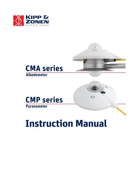
CMA seriesAlbedometer<strong>CMP</strong> seriesPyranometerInstruction Manual
IMPORTANT USER INFORMATIONReading this entire manual is recommended for full underst<strong>and</strong>ing ofthe use of this product.Should you have any comments on this manual we will be pleased toreceive them at:<strong>Kipp</strong> & <strong>Zonen</strong> B.V.Delftechpark 36, 2628 XH Delft, The Netherl<strong>and</strong>sor P.O. Box 507, 2600 AM Delft, The Netherl<strong>and</strong>sT : +31 (0)15 2755210F : +31 (0)15 2620351E : info@kippzonen.comW : www.kippzonen.com<strong>Kipp</strong> & <strong>Zonen</strong> reserves the right to make changes to the specificationswithout prior notice.WARRANTY AND LIABILITY<strong>Kipp</strong> & <strong>Zonen</strong> guarantees that the product delivered has beenthoroughly tested to ensure that it meets its published specifications.The warranty included in the conditions of delivery is valid only if theproduct has been installed <strong>and</strong> used according to the instructionssupplied by <strong>Kipp</strong> & <strong>Zonen</strong>.<strong>Kipp</strong> & <strong>Zonen</strong> shall in no event be liable for incidental or consequentialdamages, including without limitation, lost profits, loss of income, loss ofbusiness opportunities, loss of use <strong>and</strong> other related exposures,however used, rising from the faulty <strong>and</strong> incorrect use of the product.User made modifications can affect the validity of the CE declaration.COPYRIGHT © 2006 KIPP & ZONENAll rights are reserved. No part of this publication may be reproduced,stored in a retrieval system or transmitted in any form or by any means,without permission in written form from the company.Manual version: 0806Page 1
Declaration of ConformityAccording to EC guideline 89/336/EEC 73/23/EECWe<strong>Kipp</strong> & <strong>Zonen</strong> B.V.Delftechpark 362628 XH DelftThe Netherl<strong>and</strong>sDeclare under our sole responsibility that the productsType: <strong>CMP</strong> 3 / <strong>CMP</strong> 6 / <strong>CMP</strong> 11 / <strong>CMP</strong> 21 / <strong>CMP</strong> 22Name:Pyranometer<strong>and</strong>Type: CMA 6 / CMA 11Name:Albedometerto which this declaration relates are in conformity with the followingst<strong>and</strong>ardsImissions EN 50082-1 Group st<strong>and</strong>ardEmissions EN 50081-1 Group st<strong>and</strong>ardEN 55022Safety st<strong>and</strong>ard IEC 1010-1Following the provisions of the directive.B.A.H. DieterinkPresidentKIPP & ZONEN B.V.Page 2
<strong>CMP</strong>/CMA series manualTable of ContentsIMPORTANT USER INFORMATION ....................................................................................................... 1Declaration of Conformity ......................................................................................................................... 2Table of Contents ..................................................................................................................................... 31. Introduction .................................................................................................................................... 52. Installation <strong>and</strong> operation............................................................................................................... 62.1. Delivery.......................................................................................................................................... 62.2. Mechanical installation................................................................................................................... 62.2.1. Installation for measurement of global radiation ........................................................................ 62.2.2. Installation for measurement of radiation on inclined surfaces.................................................. 82.2.3. Installation for measurement of reflected radiation.................................................................... 82.2.4. Installation for measurement of diffuse radiation ....................................................................... 92.2.5. Installation for measurement of albedo...................................................................................... 92.2.6. Underwater use.......................................................................................................................... 92.3. Electrical installation .................................................................................................................... 102.4. Operation ..................................................................................................................................... 112.5. Measurement uncertainty ............................................................................................................ 112.6. Maintenance ................................................................................................................................ 133. Principle components of pyranometers ....................................................................................... 143.1. Dome ........................................................................................................................................... 143.2. Detector ....................................................................................................................................... 153.3. Housing........................................................................................................................................ 153.4. Drying cartridge............................................................................................................................ 153.5. Cable <strong>and</strong> connector.................................................................................................................... 154. Pyranometer physical properties .................................................................................................164.1. Spectral range.............................................................................................................................. 164.2. Sensitivity..................................................................................................................................... 164.3. Impedance ................................................................................................................................... 164.4. Response time............................................................................................................................. 164.5. Non-linearity................................................................................................................................. 174.6. Temperature dependence ........................................................................................................... 174.7. Tilt error........................................................................................................................................ 174.8. Zero offset A ................................................................................................................................ 174.9. Zero offset B ............................................................................................................................... 184.10. Operating temperature ............................................................................................................. 184.11. Field of view ............................................................................................................................. 184.12. Directional response ................................................................................................................ 184.13. Maximum irradiance................................................................................................................. 184.14. Non-stability.............................................................................................................................. 194.15. Spectral selectivity ................................................................................................................... 194.16. Environmental .......................................................................................................................... 194.17. Uncertainty ............................................................................................................................... 195. Calibration.................................................................................................................................... 205.1. Calibration principle ..................................................................................................................... 205.2. Calibration procedure at <strong>Kipp</strong> & <strong>Zonen</strong> ....................................................................................... 205.2.1. The calibration facility............................................................................................................... 205.2.2. Calibration procedure............................................................................................................... 205.2.3. Calculation................................................................................................................................ 215.2.4. Zero offset ................................................................................................................................ 215.3. Traceability to World Radiometric Reference .............................................................................. 215.4. Recalibration................................................................................................................................ 216. <strong>CMP</strong>/CMA models ....................................................................................................................... 236.1. <strong>CMP</strong> 6 / CMA 6............................................................................................................................ 236.2. <strong>CMP</strong> 11 / CMA 11........................................................................................................................ 23Page 3
<strong>CMP</strong>/CMA series manual6.3. <strong>CMP</strong> 21 ........................................................................................................................................ 246.4. <strong>CMP</strong> 22 ........................................................................................................................................ 246.5. <strong>CMP</strong> / CMA series performance specifications ........................................................................... 256.6. <strong>CMP</strong> / CMA series general specifications ................................................................................... 267. Frequently asked questions......................................................................................................... 278. Trouble shooting .......................................................................................................................... 28Appendix I Radiometric terminology....................................................................................................... 29Appendix II 10k thermistor specifications ............................................................................................... 30Appendix III Pt-100 specifications .......................................................................................................... 31Appendix IV classification According to WMO Guide 1996.................................................................... 32Appendix V List of World <strong>and</strong> Regional Radiation Centres.................................................................... 33Appendix VI Recalibration service.......................................................................................................... 34Page 4
<strong>CMP</strong>/CMA series manual1. IntroductionDear customer, thank you for purchasing a <strong>Kipp</strong> & <strong>Zonen</strong> instrument. Please read this manual <strong>and</strong> theseparate instruction sheet for a full underst<strong>and</strong>ing of the use of your pyranometer or albedometer.A <strong>CMP</strong> series pyranometer or CMA series albedometer is a high quality radiometer designed formeasuring short-wave irradiance on a plane surface (radiant flux, W/m 2 ) which results from the sum ofdirect solar radiation <strong>and</strong> the diffuse radiation incident from the hemisphere above the instrument.According to International St<strong>and</strong>ard ISO 9060 <strong>and</strong> the World Meteorological Organisation (WMO) apyranometer is the designated type of instrument for the measurement of global or diffuse solarradiation. All pyranometers <strong>and</strong> albedometers within the <strong>CMP</strong>/CMA series are compliant with one ofthe classes specified by the international st<strong>and</strong>ards.This manual, together with the instruction sheet, gives information related to installation, maintenance,calibration, product specifications <strong>and</strong> applications of the <strong>CMP</strong>/CMA series. Note that the smaller <strong>CMP</strong>3 pyranometer with a single glass dome is largely excluded from this manual due to the differentconstruction. However, the general definitions <strong>and</strong> principles also apply to this model.If any questions should remain, please feel free to contact your <strong>Kipp</strong> & <strong>Zonen</strong> dealer or e-mailinfo@kippzonen.comFor information about other <strong>Kipp</strong> & <strong>Zonen</strong> products or to check for any update of this manual, go towww.kippzonen.comPage 5
<strong>CMP</strong>/CMA series manual2. Installation <strong>and</strong> operation2.1. DeliveryCheck the contents of the shipment for completeness (see below) <strong>and</strong> note whether any damage hasoccurred during transport. If there is damage, a claim should be filed with the carrier immediately. Inthis case, or if the contents are incomplete, your dealer should be notified in order to facilitate therepair or replacement of the instrument.Contents of delivery:1. Radiometer2. Sun shield3. Cable with connector4. Test reports5. Instruction sheet6. Radiometer fixing kit7. 2 x desiccant bags8. Product documentation CDAlthough all <strong>CMP</strong>/CMA radiometers are weatherproof <strong>and</strong> suitable for harsh environmental conditions,they have some delicate mechanical parts. Please keep the original packaging for safe transport of theradiometer to the measurement site or for use when returning the radiometer for calibration.The calibration certificate supplied with the instrument is valid for 1 year from the date of first use bythe customer, subject to the variations in performance due to specific operating conditions that aregiven in the instrument specifications. The calibration certificate is dated relative to the time ofmanufacture, or recalibration, but the instrument does not undergo any sensitivity changes when keptin the original packing <strong>and</strong> not exposed to light. From the moment the instrument is taken from itspackaging <strong>and</strong> exposed to irradiance the sensitivity will deviate slightly with time. See the 'non-stability'performance (maximum sensitivity change per year) given in the radiometer specification list.2.2. Mechanical installationThe mechanical installation of the radiometer depends upon the measuring purpose. Differentmeasuring methods will be explained in the next paragraphs.2.2.1. Installation for measurement of global radiationThe following steps must be carefully taken for optimal performance of the instrument.1. DesiccantCheck the condition of the desiccant <strong>and</strong> replace if necessary, for example after a long storage period.2. LocationIdeally the site for the radiometer should be free from any obstructions to the horizon above the planeof the sensing element. If this is not possible, the site should be chosen in such a way that anyobstruction over the azimuth range between earliest sunrise <strong>and</strong> latest sunset should have anelevation not exceeding 5 o (the apparent sun diameter is 0.5 o ).Page 6
<strong>CMP</strong>/CMA series manualThis is important for an accurate measurement of the direct solar radiation. The diffuse solar radiationis less influenced by obstructions near the horizon. For instance, an obstruction with an elevation of 5 oover the whole azimuth range of 360 o decreases the downward diffuse solar radiation by only 0.8%.The radiometer should be readily accessible for cleaning the outer dome <strong>and</strong> inspecting the desiccantIt is evident that the radiometer should be located in such a way that a shadow will not be cast upon itat any time (for example by masts or ventilation ducts). Note that hot exhaust gas (> 100 o C) willproduce some radiation in the spectral range of the radiometer <strong>and</strong> cause an offset in themeasurements. The radiometer should be distant from light-coloured walls or other objects likely toreflect sunlight onto it, or emitting short-wave radiation.3. MountingThe <strong>CMP</strong> pyranometer is provided with two holes for 5 mm bolts. Two each of stainless steel bolts,washers, nuts <strong>and</strong> nylon insulation rings are provided in the fixing kit. The pyranometer should first besecured lightly with the bolts to a solid <strong>and</strong> stable mounting st<strong>and</strong> or platform as shown in Figure 1.After recalibration the nylon insulators must be replaced with new ones to prevent corrosion.The mounting st<strong>and</strong> temperature can vary over a wider range than the air temperature. Temperaturefluctuations of the pyranometer body can produce offset signals, therefore it is recommended to isolatethe pyranometer thermally from the mounting st<strong>and</strong> by placing it on its levelling screws. Ensure thatthere is a good electrical contact with earth to conduct away currents in the cable shield induced bylightning.Note:Figure 1 Pyranometer installationAfter recalibration <strong>and</strong>/or reinstallation the nylon insulators must be replaced with new ones tomaintain durability.4. OrientationIn principle no special orientation of the instrument is required, although the World MeteorologicalOrganisation (WMO) recommends that the signal lead is pointed towards the nearest pole, to minimiseheating of the electrical connections.Page 7
<strong>CMP</strong>/CMA series manual5. Level pyranometerAccurate measurement of the global radiation requires proper levelling of the thermopile surface. Levelthe instrument by turning the two levelling screws to bring the bubble of the spirit level centrally withinthe marked ring. For easy levelling, first use the screw nearest to the spirit level. When thepyranometer is placed horizontally using the bubble level, or when it is mounted with its base directlyon a horizontal plane, the thermopile is horizontal within 0.1 o .6. Secure pyranometerSecure the pyranometer tightly with the two stainless steel bolts. Ensure that the pyranometermaintains the correct levelled position!7. Fit cable <strong>and</strong> sun shieldLocate the cable plug correctly in the radiometer socket (it only fits one way) <strong>and</strong> screw the pluglocking ring h<strong>and</strong>-tight. Finally, clip on the sun shield to prevent excessive heating of the radiometerbody. The bubble level is visible through the top of the sun shield for routine checks.2.2.2. Installation for measurement of radiation on inclined surfacesIt is advised to pre-adjust the levelling screws on a horizontal surface for easy orientation of theinstrument parallel to the inclined surface. Because the temperature of the mounting st<strong>and</strong> is expectedto rise considerably (more than 10 o C above air temperature), the body must be thermally isolated bythe levelling screws from the st<strong>and</strong>. This will promote a thermal equilibrium between domes <strong>and</strong> body<strong>and</strong> decrease zero offset signals.2.2.3. Installation for measurement of reflected radiationIn the inverted position the pyranometer measures reflectedglobal radiation. According to the WMO the height should be 1m to 2 m above a uniform surface covered by short grass.The mounting device should not interfere significantly with thefield of view of the instrument. The upper plate preventsexcessive heating of the pyranometer body by the solarradiation <strong>and</strong>, if large enough, it keeps the lower screen free ofprecipitation. The lower glare screen prevents directillumination of the domes by the sun at sunrise <strong>and</strong> sunset <strong>and</strong>is available as an accessory kit for the <strong>CMP</strong> series.Offset signals generated in the pyranometer by thermal effectsare a factor of 5 more significant in the measurement ofreflected radiation due to the lower irradiance level. The mastshown in Figure 2 intercepts a fraction D/2πS. of the radiationcoming from the ground. In the most unfavourable situation(sun at zenith) the pyranometer shadow decreases the signalby a factor R 2 /H 2 .Figure 2 Mast constructionA rule of thumb is:A black shadow with radius = 0.1 H on the field below decreases the signal by1% <strong>and</strong> 99% of thesignal will originate from an area with radius 10 H.Page 8
<strong>CMP</strong>/CMA series manual2.2.4. Installation for measurement of diffuse radiationFor measuring sky radiation, the direct solar radiation isintercepted by a small disk or sphere. The shadow of the diskmust cover the pyranometer domes completely. However, tofollow the sun's apparent motion, a power-driven tracking deviceis necessary as shown in Figure 3.This can be done using a <strong>Kipp</strong> & <strong>Zonen</strong> sun tracker, such as themodel 2 AP, designed to track the sun accurately under allweather conditions. More information about the combination ofpyranometer <strong>and</strong> tracker is given in the sun tracker manual.Alternatively, a static shadow ring can be used to intercept thedirect solar radiation; but it is less accurate <strong>and</strong> may requireperiodic manual adjustment. At times the shadow ring alsointercepts a proportion of the diffuse sky radiation. Therefore,corrections for this to the recorded data are necessary.Figure 3 2AP Sun Tracker withshaded pyranometer<strong>Kipp</strong> & <strong>Zonen</strong> produces a universal shadow ring, model CM 121, which is suitable for use at alllatitudes. In the CM 121 manual, installation instructions <strong>and</strong> correction factors are given.2.2.5. Installation for measurement of albedoAn albedometer measures both the global solar radiation <strong>and</strong> thereflected radiation form the surface below. It can be configuredfrom two <strong>CMP</strong> series pyranometers <strong>and</strong> a suitable mountingplate, or by using a CMA series integrated albedometer.The requirements for installation of the upper <strong>and</strong> lowerpyranometers are the same as in paragraphs 2.2.1 <strong>and</strong> 2.2.3 forglobal <strong>and</strong> reflected radiation. A typical arrangement is shown inFigure 4. According to the WMO the height should be 1 m to 2 mabove a uniform surface covered by short grass.Installation of the CMA series differs slightly because there areno levelling screws. The integrated mounting rod is fixed to themast. CMA has an integrated lower glare screen to preventdirect illumination of the domes by the sun at sunrise <strong>and</strong> sunset.The mast shown intercepts a fraction D/2πS of the radiation thatis coming from the ground. In the most unfavourable situation(sun at zenith) the pyranometer shadow decreases the signal bya factor R 2 /H 2 .Figure 4 Albedo configuration2.2.6. Underwater useThe <strong>CMP</strong>/CMA radiometers are in principle watertight according to the IP 67 st<strong>and</strong>ard. However, thehemispherical air cavity under the dome(s) acts as a negative lens. The parallel beam of direct solarradiation becomes divergent after the passage of the outer dome. Consequently the intensity at thesensor is lower than outside the dome(s). The calibrated sensitivity figure is not valid in this case <strong>and</strong>must be derived empirically.Page 9
<strong>CMP</strong>/CMA series manual2.3. Electrical installationAs st<strong>and</strong>ard the <strong>CMP</strong>/CMA is supplied with a waterproof connector pre-wired to 10 m cable with anumber of leads <strong>and</strong> a shield covered with a black sleeve. The number of connector pins <strong>and</strong> cableleads depends upon the model of radiometer <strong>and</strong> whether a temperature sensor is fitted (<strong>and</strong> whichtype). The colour code of the wires <strong>and</strong> the connector pin numbers are shown on the instruction sheet.Longer cables are available as options.Preferably, secure the radiometer with its levelling screws or mounting rod to a metal support with agood connection to earth (e.g. by using a lightning conductor).The shield of the cable is connected to the aluminium radiometer housing through the connector body.The shield at the cable end may be connected to ground at the readout equipment. Lightning caninduce high voltages in the shield but these will be led off at the pyranometer <strong>and</strong> data logger.<strong>Kipp</strong> & <strong>Zonen</strong> pyranometer cables are of low noise type, but bending the cable produces small voltagespikes, a tribo-electric <strong>and</strong> capacitance effect. Therefore, the cable must be firmly secured to minimisespurious responses during stormy weather.The impedance of the readout equipment loads the temperature compensation circuit <strong>and</strong> thethermopile. It can increase the temperature dependency of the pyranometer. The sensitivity is affectedmore than 0.1% when the load resistance is less than 100 kΩ. For this reason we recommend the useof readout equipment with an input impedance of 1 MΩ or more. The solar integrators, data loggers<strong>and</strong> chart recorders from <strong>Kipp</strong> & <strong>Zonen</strong> meet these requirements.Long cables may be used, but the cable resistance must be smaller than 0.1% of the impedance of thereadout equipment. It is evident that the use of attenuator circuits to modify the calibration factor is notrecommended because the temperature response will also be affected.A high input bias current at the readout equipment can produce several micro-Volts across theimpedance of the pyranometer <strong>and</strong> cable. The zero offset can be verified by replacing the pyranometerimpedance at the readout equipment input terminals with a resistor.The pyranometer can also be connected to a computer or data acquisition system. A low voltageanalogue input must be available. The resolution of the Analogue-to-Digital Converter (ADC) mustallow a system sensitivity of about 1 bit per W/m 2 . More resolution is not necessary during outdoorsolar radiation measurements, because pyranometers exhibit offsets up to ± 2 W/m 2 due to lack ofthermal equilibrium.For amplification of the pyranometer signal <strong>Kipp</strong> & <strong>Zonen</strong> offers the AMPBOX signal amplifier. Thisamplifier will convert the micro-Volt output from the pyranometer into a st<strong>and</strong>ard 4 – 20 mA signal. Theuse of the AMPBOX amplifier is recommended for applications with long cables (> 100 m), electricallynoisy environments or data loggers with a current-loop input. The AMPBOX can be factory adjusted tosuit the sensitivity of an individual radiometer to produce a defined range, typically 4 – 20 mArepresents 0 – 1600 W/m 2 . The CMA series have two independent signal outputs, so two AMPBOXamplifiers are required.Page 10
<strong>CMP</strong>/CMA series manual2.4. OperationAfter completing the installation the radiometer will be ready for operation.The irradiance value (E ↓Solar ) can be simply calculated by dividing the output signal (U emf ) of thepyranometer by its sensitivity (S ensitivity ) as shown in Formula 1.For calculation of the solar irradiance (global or reflected) the following formula must be applied:E =↓ SolarUSemfensitivityFormula 1E ↓Solar = Solar radiation [W/m 2 ]U emf = Output of radiometer [µV]S ensitivity = Sensitivity of radiometer [µV/W/m 2 ]To be certain that the quality of the data is of a high st<strong>and</strong>ard, care must be taken with daily maintenanceof the radiometer. Once a voltage measurement is taken, nothing can be done to retrospectively improvethe quality of that measurement.2.5. Measurement uncertaintyWhen a pyranometer is in operation, the performance of it is correlated to a number of parameters,such as temperature, level of irradiance, angle of incidence, etc. Normally, the supplied sensitivityfigure is used to calculate the irradiances. If the conditions differ significantly from calibrationconditions, uncertainty in the calculated irradiances must be expected.For a secondary st<strong>and</strong>ard instrument (the highest quality) the WMO expects maximum errors in thehourly radiation totals of 3%. In the daily total an error of 2% is expected, because some responsevariations cancel each other out if the integration period is long. <strong>Kipp</strong> & <strong>Zonen</strong> expects maximumuncertainty of 2% for hourly totals <strong>and</strong> 1% for daily totals for the <strong>CMP</strong> 22 pyranometer. Many years ofexperience has shown that pyranometer performance can be improved concerning zero offset type A byusing a well designed ventilation system. The <strong>Kipp</strong> & <strong>Zonen</strong> CV 2 ventilation unit is recommended tominimise this small remaining error.For the <strong>CMP</strong> 22 the effect of each parameter on the sensitivity can be shown separately.The non-linearity error, the sensitivity variation with irradiance, is the same for any <strong>CMP</strong> 22 <strong>and</strong> isshown in Figure 5 for a range from 0 to 1000 W/m 2 referred to the calibration at 500 W/m 2 .Figure 5 Non-linearity sensitivity variation of a <strong>CMP</strong> 22Page 11
<strong>CMP</strong>/CMA series manualThe temperature dependence of the sensitivity is a function of the individual <strong>CMP</strong> 22. For a given<strong>CMP</strong> 22 the response lies in the region between the curved lines in Figure 6. The temperaturedependence of each <strong>CMP</strong> 21 <strong>and</strong> <strong>CMP</strong> 22 pyranometer is characterised <strong>and</strong> supplied with theinstrument. Each <strong>CMP</strong> 21 <strong>and</strong> <strong>CMP</strong> 22 has a built-in temperature sensor to allow corrections to beapplied if required.Figure 6 Typical temperature dependency of a <strong>CMP</strong> 22The directional error is the summation of the azimuth <strong>and</strong> zenith error <strong>and</strong> is commonly given in %.Figure 7 shows the maximum relative zenith error in any azimuth direction for the <strong>CMP</strong> 22. Thedirectional error of each <strong>CMP</strong> 21 <strong>and</strong> <strong>CMP</strong> 22 pyranometer is characterised <strong>and</strong> supplied with theinstrument.Figure 7 Relative directional error of a <strong>CMP</strong> 22Page 12
<strong>CMP</strong>/CMA series manual2.6. MaintenanceOnce installed the radiometer needs little maintenance. The outer dome(s) must be cleaned <strong>and</strong>inspected regularly, ideally every morning. On clear windless nights the outer dome temperature ofhorizontally placed radiometers will decrease, even to the dew point temperature of the air, due toinfrared radiation exchange with the cold sky. (The effective sky temperature can be 30°C lower thanthe ground temperature). In this case dew, glazed frost or hoar frost can be precipitated on the top ofthe outer dome <strong>and</strong> can stay there for several hours in the morning. An ice cap on the dome is a strongdiffuser <strong>and</strong> increases the pyranometer signal drastically, up to 50% in the first hours after sunrise.Hoar frost disappears due to solar radiation during the morning, but should be wiped of as soon aspossible manually.The dome of the pyranometer can be ventilated continuously by a heated blower to keep the domeabove dew point temperature. The need for heating strongly depends upon local climatologicalcircumstances. Generally, heating is advised during cold seasons when frost <strong>and</strong> dew can be expected.The <strong>Kipp</strong> & <strong>Zonen</strong> CV 2 ventilation unit is specially designed for unattended operation under mostweather conditions <strong>and</strong> has a choice of heating levels.Note that the CMA albedometers <strong>and</strong> the <strong>CMP</strong> 3 pyranometer cannot be used with the CV 2 ventilationunit.A periodic check is to ensure that the radiometer is level <strong>and</strong> that the silica gel desiccant is stillcoloured orange. When the orange silica gel in the drying cartridge is turned completely transparent(normally after several months), it must be replaced by fresh silica gel as supplied in the small refillpacks. The content of one pack is sufficient for one complete refill. At the same time check that theradiometer mounting is secure <strong>and</strong> that the cable is in good condition.Some tips when changing the dessicant:- Make sure the surfaces of the radiometer <strong>and</strong> the drying cartridge that touch the rubber o-ring areclean (corrosion can do a lot of harm here <strong>and</strong> dirt, in combination with water, can cause this);- The rubber o-ring is coated with a silicon grease to improve the seal. If the rubber o-ring looks dryapply some grease to it (Vaseline will also do);- Check that the drying cartridge is tightly threaded into the radiometer body.It is very difficult to make the radiometers hermetically sealed; so, due to pressure differences betweenthe inside <strong>and</strong> the outside of the instrument, there will always be some exchange of (humid) air.The radiometer sensitivity changes with time <strong>and</strong> with exposure to radiation. Calibration every twoyears is advised. Further information about <strong>Kipp</strong> & <strong>Zonen</strong> recalibration services can be found inAppendix VI.Page 13
<strong>CMP</strong>/CMA series manual3. Principle components of pyranometersThe detector of the <strong>Kipp</strong> & <strong>Zonen</strong> <strong>CMP</strong>/CMA series pyranometer is based on a passive thermalsensing element called a thermopile. Although the detector construction differs from model to model,the fundamental working principle is applicable to all <strong>CMP</strong>/CMA series radiometers.The thermopile responds to the total power absorbed by the black surface coating, which is a nonspectrallyselective paint, <strong>and</strong> warm up. The heat generated flows through a thermal resistance to theheat-sink (the pyranometer body). The temperature difference across the thermal resistance of thedetector is converted into a voltage as a linear function of the absorbed solar irradiance.The rise of temperature is easily affected by wind, rain <strong>and</strong> thermal radiation losses to the environment('cold' sky). Therefore the detector is shielded by two domes (the entry-level <strong>CMP</strong> 3 has only one dometo reduce size <strong>and</strong> cost). These domes allow equal transmittance of the direct solar component forevery position of the sun on the celestial sphere. A drying cartridge (dessicator) in the radiometerhousing is filled with silica gel <strong>and</strong> prevents dew on the inner sides of the domes, which can cool downconsiderably on clear windless nights.Figure 8 Construction details of a pyranometer3.1. DomeThe dome material of the radiometer defines the spectral measurement range of the instrument. Ingeneral about 97 – 98% of the solar radiation spectrum will be transmitted through the domes <strong>and</strong> willbe absorbed by the detector. The solar irradiance can come from any direction within the hemisphereabove the radiometer <strong>and</strong> therefore the domes are designed to minimize errors in measurement at allincident angles.<strong>CMP</strong>/CMA series radiometers, except the <strong>CMP</strong>/CM 3, have two high optical grade hemisphericaldomes, one inner dome <strong>and</strong> one outer dome. In the chapter ‘pyranometer physical properties’ thephysical relation between dome <strong>and</strong> pyranometer performance will be explained.For each particular model the specific dome material <strong>and</strong> spectral range is shown in the chaptercontaining the instrument specifications.Page 14
<strong>CMP</strong>/CMA series manual3.2. DetectorThe thermopile sensing element is made up of a large number of thermocouple junction pairsconnected electrically in series. The absorption of thermal radiation by one of the thermocouplejunctions, called the active (or ‘hot’) junction, increases its temperature. The differential temperaturebetween the active junction <strong>and</strong> a reference (‘cold’) junction kept at a fixed temperature produces anelectromotive force directly proportional to the differential temperature created. This is a thermoelectriceffect. The sensitivity of a pyranometer depends on the individual physical properties of the thermopile<strong>and</strong> construction. The sensitivity of each thermopile is unique <strong>and</strong> therefore each radiometer hasunique calibration factor, even with the same radiometer model.On the top surface of the sensor a black paint is deposited which has a very rough structure containingmany micro-cavities that effectively ‘’trap’’ more than 97% of the incident radiation in a broad spectralrange. Furthermore, the spectral selectivity is less than 2%. This means that within the spectral rangeof the pyranometer, the absorption for each wavelength is equal to within 2%. The black paintedsensing element forms the detector. Considering the long-term stability of the instrument, the blackpaint is one of the most crucial <strong>and</strong> delicate parts of the pyranometer. <strong>Kipp</strong> & <strong>Zonen</strong> black paint givesthe best possible stability over a long period of time under all meteorological circumstances.3.3. HousingThe radiometer housing accommodates all fundamental pyranometer parts. The anodized Aluminiumparts are light weight <strong>and</strong> give a high mechanical <strong>and</strong> thermal stability to the instrument. Due to its finemechanical construction all pyranometers are virtually sealed <strong>and</strong> comply to the international st<strong>and</strong>ardIP 67. Each pyranometer model can be leveled by using the bubble level <strong>and</strong> two leveling feet. Forease of maintenance the bubble level is situated next to the dome of the instrument <strong>and</strong> due to thespecial shape of the sun shield it is visible from above. The sun shield acts to protects all the externalparts from radiation <strong>and</strong> to reduce solar heating of the housing.3.4. Drying cartridgeIn case moisture enters the radiometer body the silica-gel desiccant regulates the humidity level insidethe pyranometer. Initially the desiccant will have an orange color. After some time it becomes saturatedwith moisture <strong>and</strong> the colour will change to become clear (transparent). At this time the contents of thedrying cartridge should be replaced with fresh, unsaturated orange colored desiccant as soon aspossible. Replacement desiccant is available through <strong>Kipp</strong> & <strong>Zonen</strong> distributors.3.5. Cable <strong>and</strong> connectorFor ease of installation <strong>and</strong> replacement during recalibration of the radiometer, the <strong>CMP</strong>/CMA seriesare provided with a weather proof signal cable connector.<strong>Kipp</strong> & <strong>Zonen</strong> radiometers use a custom-made cable that is selected as a low noise type particularlysuited to h<strong>and</strong>le the low voltage output of the thermopile or of a temperature sensor.The shield of the cable is connected to the metal body of the connector <strong>and</strong> preferably should beconnected to ground at the readout equipment. Cables come pre-wired to the connector plug in arange of lengths.Page 15
<strong>CMP</strong>/CMA series manual4. Pyranometer physical properties4.1. Spectral rangeThe spectrum of the solar radiation reaching the Earth’s surface is in the wavelength range between280 nm <strong>and</strong> 4000 nm, extending from ultraviolet (UV) to the far infrared (FIR) as shown in Figure 9.Due to the excellent physical properties of the glass dome <strong>and</strong> black absorber paint, <strong>Kipp</strong> & <strong>Zonen</strong><strong>CMP</strong>/CMA series radiometers are equally sensitive in a wide spectral range. 97-98% of the totalenergy will be absorbed by the thermal detector. The <strong>CMP</strong> 22 pyranometer has a wider spectral rangedue to the quartz domes used in its construction.Figure 9 Solar irradiance spectrum at the Earth’s surface <strong>and</strong> pyranometer response4.2. SensitivityThe radiometer thermopile sensitivity is mainly determined by the physical properties of the detectoritself. The thermoelectric power, thermal conductivity of the junctions <strong>and</strong> the overall dimensions of thesensing element are related to its sensitivity.4.3. ImpedanceThe radiometer impedance is defined as the total electrical impedance at the radiometer outputconnector fitted to the housing. It arises from the electrical resistance in the thermal junctions, wires<strong>and</strong> passive electronics within the radiometer.4.4. Response timeAny measuring device requires a certain time to react to a change in the parameter being measured.The radiometer requires time to respond to change in the incident radiation. The response time isnormally quoted as the time for the output to reach 95% (sometimes 63%) of the final value following astep-change in irradiance. It is determined by the physical properties of the thermopile <strong>and</strong> theradiometer construction. <strong>CMP</strong>/CMA series radiometers have a fast response, which makes themsuitable for measuring solar radiation under variable weather conditions.Page 16
<strong>CMP</strong>/CMA series manual4.5. Non-linearityThe non-linearity of a radiometer is the percentage deviation in the sensitivity over an irradiance rangefrom 0 to 1000 W . m -2 compared to the sensitivity calibration irradiance of 500 W . m -2 . The non-linearityeffect is due to convective <strong>and</strong> radiative heat losses at the black absorber surface which make theconditional thermal equilibrium of the radiometer non-linear.4.6. Temperature dependenceThe sensitivity change of the radiometer with ambient temperature change is related to the thermodynamicsof the radiometer construction. The temperature dependence is given as percent deviationwith respect to the calibrated sensitivity at +20°C. Some of the <strong>CMP</strong>/CMA series radiometer modelshave passive electrical compensation circuits to minimise this effect. Each <strong>CMP</strong> 21 <strong>and</strong> <strong>CMP</strong> 22pyranometer is supplied with an individual test certificate stating the temperature dependency in therange from -20°C to +50°C, at 10°C intervals. The <strong>CMP</strong> 21 <strong>and</strong> <strong>CMP</strong> 22 are fitted as st<strong>and</strong>ard with aninternal temperature sensor to allow sensitivity corrections to be applied if desired.4.7. Tilt errorThis is the deviation from the sensitivity at 0° tilt (exactly horizontal) over the range from 0° to 90° tiltunder 1000 W . m -2 normal incidence irradiance. The tilt response is proportional to the incidentradiation. The error could be corrected for, in applications where it is necessary to install thepyranometer on an inclined surface, but is usually insignificant.4.8. Zero offset ABy physical laws any object having a certain temperature will exchange radiation with its surroundings.The domes of upward facing radiometers will exchange radiation primarily with the relatively coldatmosphere. In general, the atmosphere will be cooler than the ambient temperature at the Earth’ssurface. For example, a clear sky can have an effective temperature up to 50°C cooler, whereas anovercast sky will have roughly the same temperature as the Earth’s surface. Due to this thepyranometer domes will ‘lose’ energy to the colder atmosphere by means of radiative transfer. Thiscauses the dome to become cooler than the rest of the instrument. This temperature differencebetween the detector <strong>and</strong> the instrument housing will generate a small negative output signal which iscommonly called Zero Offset type A. This effect is minimized by using an inner dome. This inner domeacts as a ‘radiation buffer’. The above is illustrated in Figure 10.This effect can be minimized by applying appropriateventilation of the instrument. The CV 2 ventilation unit isspecially designed for the <strong>CMP</strong> series, except <strong>CMP</strong> 3.Figure 10 Zero Offset type APage 17
<strong>CMP</strong>/CMA series manual4.9. Zero offset BProportionally to the ambient temperature the instrument temperature varies <strong>and</strong> causes heat currentsinside the instrument. This will cause an offset commonly called Zero Offset type B. It is quantified asthe response in W/m 2 to a 5 K/hr change in ambient temperature.4.10. Operating temperatureThe operating temperature range of the radiometer is determined by the physical properties of theindividual parts. Within the specified temperature range <strong>Kipp</strong> & <strong>Zonen</strong> radiometers can be operatedsafely. Outside this temperature range special precautions should be taken to prevent any physicaldamage or performance loss of the radiometer. Please contact your distributor for further informationregarding operation in unusually harsh temperature conditions.4.11. Field of viewThe field of view is defined as the unobstructed open viewing angle of the radiometer. ISO <strong>and</strong> WMOrequire that a pyranometer for the measurement of global solar radiation has a field of view of 180° inall directions (i.e. a hemisphere). The inherent field of view of the instrument should not be confusedwith the clear field of view of the installation location.4.12. Directional responseRadiation incident on a flat horizontal surface originatingfrom a point source with a defined zenith position will havean intensity value proportional to the cosine of the zenithangle of incidence. This is sometimes called the ‘cosinelaw’or ‘cosine-response’ <strong>and</strong> is illustrated in figure 11.Ideally a pyranometer has a directional response which isexactly the same as the cosine-law. However, in apyranometer the directional response is influenced by thequality, dimensions <strong>and</strong> construction of the domes. Themaximum deviation from the ideal cosine-response of thepyranometer is given up to 80° angle of incidence withrespect to 1000 W/m 2 irradiance at normal incidence (0°).Figure 11 Solar zenith angle4.13. Maximum irradianceThe maximum irradiance is defined as the total irradiance level beyond which physical damage mayoccur to the instrument.Page 18
<strong>CMP</strong>/CMA series manual5. Calibration5.1. Calibration principleAn ideal radiometer gives voltage output that is proportional to the absolute irradiance level. Thisrelationship can be expressed as a constant ratio called ‘sensitivity’ (S ensitivity ).The sensitivity figure of a particular radiometer is unique. It is determined in the manufacturer'slaboratory by comparison against a reference radiometer of similar type. The reference radiometer iscalibrated outdoors regularly at the World Radiation Centre (WRC) at Davos, Switzerl<strong>and</strong>. The spectralcontent of the laboratory calibration lamp differs from the outdoor solar spectrum at the WorldRadiation Centre. However, this has no consequences for the transfer of calibration, because st<strong>and</strong>ard<strong>and</strong> test radiometers have the same black coating <strong>and</strong> domes.The supplied sensitivity figure is valid for the following conditions:• An ambient temperature of +20°C.• For a horizontal radiometer <strong>and</strong> for a tilted radiometer.• Normal incident radiation of 500 W/m 2 .For any other condition the sensitivity figure can be used within uncertainty b<strong>and</strong>s given in thespecifications for each model.A summary of calibration methods is also found in the WMO guide of 1996.5.2. Calibration procedure at <strong>Kipp</strong> & <strong>Zonen</strong>5.2.1. The calibration facilityThe indoor calibration procedure, according to ISO 9847 Appendix III, is based on a side-by-sidecomparison with a reference radiometer under a stable artificial sun. <strong>Kipp</strong> & <strong>Zonen</strong> uses a 150 WMetal-Halide high-pressure gas discharge lamp with voltage stabilisation. Behind the lamp is a reflectorwith a diameter of 16.2 cm. The reflector is 110 cm above the radiometers producing a vertical beam.The irradiance at the radiometers is approximately 500 W/m².To minimise stray light from the walls <strong>and</strong> the operator, the light is restricted to a small cone around thetwo radiometers. The unknown radiometer 'a' <strong>and</strong> the reference radiometer 'b' are placed side by sideon a small table. The table can rotate to interchange the positions (1 <strong>and</strong> 2) of the radiometers. Thelamp is centred on the rotating axis of this table. Actually there is no normal incidence of the radiation,but the angle of incidence is the same for both radiometers (3°) so this cannot give rise to errors. Thetwo radiometers are not levelled with the screws, but placed on their bases. The effect of the smallbeam tilt is negligible (compare cos. 3° = 0.9986 <strong>and</strong> cos. 4° = 0.9976).5.2.2. Calibration procedureAfter illuminating for 30 seconds, the output voltages of both radiometers are integrated over 30seconds. Next, both radiometers are covered. After 30 seconds the zero offset signals of bothradiometers are integrated, again over a period of 30 seconds. The irradiance at position 1 (radiometer'a') may be slightly different from that at position 2 (radiometer 'b') due to asymmetry in the lamp optics,etc. Therefore the radiometers are interchanged by rotating the table <strong>and</strong> the whole procedure isrepeated.Page 20
<strong>CMP</strong>/CMA series manual5.2.3. CalculationThe sensitivity of the unknown pyranometer is calculated with formula 2:Sa=A + A'⋅B + B'sbFormula 2S b = Sensitivity of the reference radiometer at +20 °C.A = Output of test radiometer at position 1A’ = Output of test radiometer at position 2B = Output of reference radiometer at position 2B’ = Output of reference radiometer at position 1S a = Sensitivity of the test radiometer at +20 °C.Output = mean value at 100% response minus zero offset signal5.2.4. Zero offsetThe lamp housing <strong>and</strong> beam restrictors heat up <strong>and</strong> emit long-wave infrared radiation, which heats upthe outer glass dome <strong>and</strong>, indirectly, the inner one. When the radiometers are shaded, there stillremains a small signal of up to +20 µV due to long-wave infrared radiation from the inner dome to thesensor. This zero offset is decreasing with a time constant (1/e) of several minutes.A zero offset is also embodied in the response due to illumination. To correct for this unwantedresponse, the zero offset read after 60 seconds of shading is subtracted.5.3. Traceability to World Radiometric ReferenceReference radiometers, which are calibrated annually by the World Radiation Centre in Davos, areused for the calibration of radiometers manufactured by <strong>Kipp</strong> & <strong>Zonen</strong>. The reference radiometers arefully characterized, i.e. linearity, temperature dependence <strong>and</strong> directional response are recorded.<strong>Kipp</strong> & <strong>Zonen</strong> keeps two reference radiometers for each radiometer model. These referenceradiometers are sent alternate years to WRC for calibration, so production <strong>and</strong> calibration in Delft cancarry on without interruption.5.4. RecalibrationRadiometer sensitivity changes with time <strong>and</strong> with exposure to radiation. Periodic calibration every twoyears is advised.Accurate calibrations can be done outdoors under clear conditions by comparison with a referencepyrheliometer. Many national or regional weather services have calibration facilities. Their st<strong>and</strong>ardpyrheliometer is compared with the World Radiometric Reference at Davos, Switzerl<strong>and</strong>. Thisembodies several absolute cavity (black body) pyrheliometers. Information about regional calibrationcentres can be found in appendix V.Page 21
<strong>CMP</strong>/CMA series manualThere are several procedures for transferring calibration from a narrow field of view instrument(pyrheliometer) to a wide field of view instrument (pyranometer). For example the direct component ofthe solar radiation is eliminated temporarily from the pyranometer by shading the whole outer dome ofthe instrument with a disk. There is however no thermal equilibrium with this method <strong>and</strong> somepyranometer models show zero-offset drift.There is another procedure, during which the unknown pyranometer remains in its normal operatingcondition. This 'component' method involves measuring the direct component with a pyrheliometer <strong>and</strong>the diffuse component with a disk shaded pyranometer. As, during a clear day, the diffuse radiation isonly about 10% of the global radiation, the sensitivity of the second pyranometer does not need to beknown very accurately. Both procedures are suitable to obtain a working st<strong>and</strong>ard pyranometer. Thelatter is extensively described in international st<strong>and</strong>ard ISO 9846.Transfer from the working st<strong>and</strong>ard pyranometer to other pyranometers can be done in sunlight. Thepyranometers must be mounted side by side so that each views the same sky dome. It is desirable tointegrate, or average, the outputs over a period of time <strong>and</strong> then compute the calibration constants onthe basis of these averages. This reduces the errors due to changing parameters during the day.Transfer from another pyranometer in the laboratory is only possible when both pyranometers are ofthe same type <strong>and</strong> have the same glass domes <strong>and</strong> optical coatings. <strong>Kipp</strong> & <strong>Zonen</strong> can recalibratepyranometers according to this method.Page 22
<strong>CMP</strong>/CMA series manual6. <strong>CMP</strong>/CMA modelsThe <strong>CMP</strong> series offers 5 different models in the range from <strong>CMP</strong> 3 up to <strong>CMP</strong> 22. The mechanicalconstruction of the <strong>CMP</strong> 3 differs from the others in that it has a single dome, smaller housingdimensions <strong>and</strong> no drying cartridge (the housing is completely sealed). Features <strong>and</strong> specification ofthe double dome pyranometers in the range from <strong>CMP</strong> 6 to <strong>CMP</strong> 22 are specified in this chapter. The<strong>CMP</strong>/CMA series is designed for measuring the irradiance (radiant-flux, W/m 2 ) on a plane surface,which results from the direct solar irradiance <strong>and</strong> from the diffuse radiation incident from thehemisphere above.A <strong>CMP</strong>/CMA radiometer includes an integrated bubble level, refillable drying cartridge, white snap-onsun shield, <strong>and</strong> a shielded signal output cable with connector. In addition, the CMA seriesalbedometers also have an integrated conical lower glare shield to prevent illumination of the lowerglass dome at sunrise <strong>and</strong> sunset. The albedometers are equipped with a mounting rod for attachmentto a mast. All albedometers are supplied with a calibration certificate indicating both the upper <strong>and</strong>lower sensor sensitivities.The <strong>CMP</strong> series (except <strong>CMP</strong> 3) can be used in conjunction with the <strong>Kipp</strong> & <strong>Zonen</strong> CV 2 ventilationunit for enhanced measurement performance <strong>and</strong> overall reduced instrument maintenance.For measuring the diffuse component of solar radiation only, the direct solar component can beshielded statically from the <strong>CMP</strong> pyranometers by the <strong>Kipp</strong> & <strong>Zonen</strong> shadow ring CM 121, <strong>and</strong> fullyautomatically by the 2 AP sun tracker with shading system.6.1. <strong>CMP</strong> 6 / CMA 6Fully compliant with all ISO-9060 specification criteria for an ISO First Class pyranometer, the<strong>CMP</strong>/CMA 6 features a sixty-four junction (connected in series) thermocouple sensing element. Thesensing element is coated with a highly stable carbon based inorganic coating, which delivers excellentspectral absorption <strong>and</strong> long-term stability characteristics. The detector is housed under two concentricglass domes which are 2 mm thick.The albedo version is constructed around two <strong>CMP</strong> 6 pyranometer sensors <strong>and</strong> also complies with theISO classification. Both sensors are contained in a single housing <strong>and</strong> have individual sensitivities.6.2. <strong>CMP</strong> 11 / CMA 11Fully compliant with all ISO-9060 specification criteria for an ISO Secondary St<strong>and</strong>ard pyranometer,the <strong>CMP</strong> 11 features a 32 junction (connected in series) thermocouple sensing element which hasfaster response than the <strong>CMP</strong> 6 / CMA 6. Passive temperature compensation is included for improvedtemperature dependence of sensitivity <strong>and</strong> non-linearity is reduced. The sensing element is housedunder two higher quality concentric glass domes which are 2 mm thick <strong>and</strong> provide improveddirectional error. The radiometric leveling is more accurate than in <strong>CMP</strong> 6 / CMA 6.CMA 11 is constructed around two <strong>CMP</strong> 11 pyranometer sensors. Both sensors are contained in asingle housing <strong>and</strong> have individual sensitivities.Page 23
<strong>CMP</strong>/CMA series manual6.3. <strong>CMP</strong> 21<strong>CMP</strong> 21 is a high precision scientific pyranometer based upon the <strong>CMP</strong> 11 but with individualoptimisation <strong>and</strong> characterisation <strong>and</strong> an integrated housing temperature sensor. <strong>CMP</strong> exceeds theISO-9060 specification criteria for an ISO Secondary St<strong>and</strong>ard pyranometerThe special features of the <strong>CMP</strong> 21 are:• Individually optimised <strong>and</strong> characterised temperature dependence.• Individually characterised directional response.• Integrated housing temperature sensor.6.4. <strong>CMP</strong> 22<strong>CMP</strong> 22 is a high precision scientific pyranometer base upon the <strong>CMP</strong> 21 but with strictly selectedquartz domes which are 4 mm thick. <strong>CMP</strong> 22 has an extended spectral range to match pyrheliometerswith quartz windows. Because of the high optical quality <strong>and</strong> higher refractive index of the quartzdomes the directional error is reduced to less than 5 W/m 2 .The zero offset behaviour is fundamentally improved in two ways:The zero offset caused by changing instrument temperature is negligible, because of the very wellbalanced thermopile construction.The zero offset due to the difference between sensor <strong>and</strong> dome temperature (e.g. Far InfraredRadiation absorption or emission by the outer dome) is minimised using an improved thermal couplingof sensor <strong>and</strong> top of dome. Thicker domes, both of 4mm, <strong>and</strong> the 50% higher thermal conductivity ofquartz, compared to glass, improve this thermal coupling.<strong>CMP</strong> 22 features are:• Negligible thermal gradient zero-offset.• Lowest zero-offset due to FIR radiation.• Broadened spectral range 200 – 3600 nm.• Directional error < 5 W/m 2 .• Lowest temperature dependency of sensitivity.Like the <strong>CMP</strong> 11 <strong>and</strong> <strong>CMP</strong> 21 pyranometers, the <strong>CMP</strong> 22 complies with the specifications for the bestof three classes of pyranometer, ‘High quality’, as defined in the 'Guide to meteorological Instruments<strong>and</strong> Methods of Observation', sixth edition, 1996, of the World Meteorological Organisation (*WMO)Geneva, Switzerl<strong>and</strong>. Most specifications of the <strong>CMP</strong> 22 are twice as good as required.* The WMO classification is adapted from the international st<strong>and</strong>ard ISO 9060 (1990). Herein ‘highquality’ class is referred to as ‘secondary st<strong>and</strong>ard’.Page 24
<strong>CMP</strong>/CMA series manual6.5. <strong>CMP</strong> / CMA series performance specificationsSpecification Unit <strong>CMP</strong> 6/ CMA 6 <strong>CMP</strong> 11 / CMA 11 <strong>CMP</strong> 21 <strong>CMP</strong> 22 DefinitionSpectral range µm 310 - 2800 310 - 2800 310 - 2800 200 - 3600 50 % response pointSensitivity µV/W/m² 5 to 18 7 to 14 7 to 14 7 to 14 Signal output for 1 W/m² irradianceImpedance Ω 20 to 200 10 to 100 10 to 100 10 to 100 At instrument housing connectorResponse times< 18 < 5 < 5 < 5 95% of final value< 6 < 1.7 < 1.7 < 1.7 63 % of final valueNon-linearity % < 1 < 0.2 < 0.2 < 0.2 From 0 to 1000 W/m² irradianceTemperature dependence ofsensitivity%< 4 < 1 < 1* < 0.5*Variation in range - 10 °C to + 40 °Cfrom value at + 20 °C*(- 20 °C to + 50 °C)Tilt error % < 1 < 0.2 < 0.2 < 0.2 Deviation when facing downwardsZero offset A W/m² < 15 < 7 < 7 < 3 At 0 to - 200 W/m² of IR net radiationZero offset B W/m² < 4 < 2 < 2 < 1 At 5 K/h temperature change rateOperating temperature °C -40 to +80 -40 to +80 -40 to +80 -40 to +80 Storage temperature is the sameField of view 180º 180º 180º 180º HemisphericalDirectional error W/m 2 < 20 < 10 < 10 < 5 At 80° with 1000 W/m² irradianceMaximum irradiance W/m 2 2000 4000 4000 4000 Level above which damage may occurNon-stability % < 1 < 0.5 < 0.5 < 0.5 Variation in sensitivity per yearHumidity % RH 0 - 100 0 - 100 0 - 100 0 - 100 Relative HumidityUncertainty in daily total % < 5 < 2 < 2 < 1 95 % confidence levelPage 25
<strong>CMP</strong>/CMA series manual6.6. <strong>CMP</strong> / CMA series general specificationsPage 26
<strong>CMP</strong>/CMA series manual7. Frequently asked questionsThe most frequently asked questions are listed below. For an update refer to the <strong>Kipp</strong> & <strong>Zonen</strong> websiteat www.kippzonen.com Negative output during night-time measurements?This error is related to Zero Offset type A. Normally this zero offset is present when the inner dome hasa different temperature from the cold junctions of the sensor. Practically this is always the case whenthere is a clear sky. Because of the low effective sky temperature (< 0°C) the Earth’s surface emitsroughly 100 W/m 2 of long-wave infrared radiation upwards. The outer glass dome of a pyranometeralso has this emission <strong>and</strong> is cooling down several degrees below air temperature (the emissivity ofglass for the particular wavelength region is nearly 1).The emitted heat is attracted from the body (by conduction in the dome), from the air (by wind) <strong>and</strong>from the inner dome (through infrared radiation). The inner dome is cooling down too <strong>and</strong> will attractheat from the body by conduction <strong>and</strong> from the sensor by the net infrared radiation. The latter heat flowis opposite to the heat flow from absorbed solar radiation <strong>and</strong> causes the well-known zero depressionat night. This negative zero offset is also present on a clear day but is hidden in the solar radiationsignal.Zero Offset type A can be checked by placing a light <strong>and</strong> IR reflecting cap over the pyranometer. Theresponse to solar radiation will decay with a time constant (1/e) of 1 second, but the dome temperaturewill go to equilibrium with a time constant of several minutes. So after half a minute the remainingsignal represents mainly Zero Offset type A.Good ventilation of domes <strong>and</strong> body is the solution to minimising zero offsets. <strong>Kipp</strong> & <strong>Zonen</strong> advisesthe CV 2 ventilation unit for optimal ventilation <strong>and</strong> suppression of zero offset type A. Using the CV 2zero offset type A will decrease by ~ 50%. Maximum <strong>and</strong> minimum irradiation quantities?Due to possible reflection from clouds the global irradiance at sea level can rise above the extraterrestrialdirect irradiance of 1367 W/m 2 at the top of the atmosphere. Values up to 1500 W/m 2 havebeen reported.Because the clouds move, this irradiance value mostly appears as short events of a few minutesduration. What is the primary entry point for humidity?The drying cartridge seal <strong>and</strong> the silicon glue of the domes are not fully airtight. Is the pyranometer sensitivity affected by the length of the signal cable?With longer cable lengths the impedance increases, however it does not affect the radiometersensitivity for the following reason. The impedance of the voltage measurement device is at least10000 times more than the impedance of the pyranometer plus cable. Therefore the current that goesthrough the readout cable is negligible <strong>and</strong> won’t generate an offset. However, the loading may affectthe temperature compensation circuit to some extent.Page 27
<strong>CMP</strong>/CMA series manual8. Trouble shootingThe following contains a procedure for checking the instrument in case it appears that it does notfunction as it should.Trouble shooting:Output signal fails or shows improbable results:• Check the wires are properly connected to the readout equipment.• Check the instrument location. Are there any obstructions that cast a shadow on the instrumentby blocking the direct sun during some part of the day?• Check the dome, it should be clear <strong>and</strong> clean. If water is deposited on the inside, please changethe desiccant. If too much water is deposited internally the drying cartridge should be removed<strong>and</strong> the instrument warmed to dry it.• Check instrument impedance (see specifications for expected values).• Check data logger or integrator offset by connecting a dummy load (100 Ohm resistor). Thisshould give a “zero” reading.• Check levelling (bubble inside ring)If water or ice is deposited on the dome, clean it. Probably water droplets will evaporate in less thanone hour under sunlight.Any visible damage or malfunction should be reported to your distributor, who will suggest appropriateaction.Page 28
<strong>CMP</strong>/CMA series manualAppendix I Radiometric terminologyTermExplanationAlbedoThe portion of incoming radiation which is reflected by a surfaceAzimuth angle Angle in horizontal direction (0-360°)Angle of incidenceCosine responseDiffuse solar irradianceDirect solar irradianceIncident angle from zenith (vertical)Detector response according to the cosine lawSolar radiation, scattered by water vapor, dust <strong>and</strong> other particles asit passes through the atmosphereRadiation that has travelled a straight path from the sunGlobal solar irradiance Total irradiance falling on a horizontal surface (Diffuse + Direct ⋅ cos α)Irradiance Radiant flux density (W/m 2 )Long-wave radiation Radiation with wavelengths > 4 µm <strong>and</strong> < 100 µmPyranometerPyrgeometerPyrheliometerRadiometer suitable to measure short-wave global radiationRadiometer suitable to measure downward long-wave radiationRadiometer suitable to measure direct irradianceShort-wave radiation Radiation with wavelengths > 280 nm <strong>and</strong> < 4 µmThermopileWMOWRCWRRWSGZenith angleThermal detector mad up of many thermocouple junctionsWorld Meteorological OrganisationWorld Radiation Center (in Davos, Switzerl<strong>and</strong>)World Radiation Reference (st<strong>and</strong>ard radiation scale)World St<strong>and</strong>ard Group (radiometer st<strong>and</strong>ards maintained in Davos)Angle from zenith (0°, vertical)Page 29
<strong>CMP</strong>/CMA series manualAppendix II 10k thermistor specificationsYSI Thermistor 44031 - Resistance versus Temperature in °CYSI 44031 Temperature vs. ResistanceTemperature Resistance Temperature Resistance Temperature Resistance[ °C ] [ °F ] [ Ohm ] [ °C ] [ °F ] [ Ohm ] [ °C ] [ °F ] [ Ohm ]-30 -22.0 135,200 0 32.0 29,490 30 86.0 8,194-29 -20.2 127,900 1 33.8 28,150 31 87.8 7,880-28 -18.4 121,100 2 35.6 26,890 32 89.6 7,579-27 -16.6 114,600 3 37.4 25,690 33 91.4 7,291-26 -14.8 108,600 4 39.2 24,550 34 93.2 7,016-25 -13.0 102,900 5 41.0 23,460 35 95.0 6,752-24 -11.2 97,490 6 42.8 22,430 36 96.8 6,500-23 -9.4 92,430 7 44.6 21,450 37 98.6 6,258-22 -7.6 87,660 8 46.4 20,520 38 100.4 6,026-21 -5.8 83,160 9 48.2 19,630 39 102.2 5,805-20 -4.0 78,910 10 50.0 18,790 40 104.0 5,592-19 -2.2 74,910 11 51.8 17,980 41 105.8 5,389-18 -0.4 71,130 12 53.6 17,220 42 107.6 5,193-17 1.4 67,570 13 55.4 16,490 43 109.4 5,006-16 3.2 64,200 14 57.2 15,790 44 111.2 4,827-15 5.0 61,020 15 59.0 15,130 45 113.0 4,655-14 6.8 58,010 16 60.8 14,500 46 114.8 4,489-13 8.6 55,170 17 62.6 13,900 47 116.6 4,331-12 10.4 52,480 18 64.4 13,330 48 118.4 4,179-11 12.2 49,940 19 66.2 12,790 49 120.2 4,033-10 14.0 47,540 20 68.0 12,260 50 122.0 3,893-9 15.8 45,270 21 69.8 11,770 51 123.8 3,758-8 17.6 43,110 22 71.6 11,290 52 125.6 3,629-7 19.4 41,070 23 73.4 10,840 53 127.4 3,504-6 21.2 39,140 24 75.2 10,410 54 129.2 3,385-5 23.0 37,310 25 77.0 10,000 55 131.0 3,270-4 24.8 35,570 26 78.8 9,605 56 132.8 3,160-3 26.6 33,930 27 80.6 9,227 57 134.6 3,054-2 28.4 32,370 28 82.4 8,867 58 136.4 2,952-1 30.2 30,890 29 84.2 8,523 59 138.2 2,854Page 30
<strong>CMP</strong>/CMA series manualAppendix III Pt-100 specificationsPt-100 - Resistance versus Temperature in ºC <strong>and</strong> ºFPt-100 Temperature vs. ResistanceTemperature Resistance Temperature Resistance Temperature Resistance[ °C ] [ °F ] [ Ohm ] [ °C ] [ °F ] [ Ohm ] [ °C ] [ °F ] [ Ohm ]-30 -22.0 88.2 0 32.0 100.0 30 86.0 111.7-29 -20.2 88.6 1 33.8 100.4 31 87.8 112.1-28 -18.4 89.0 2 35.6 100.8 32 89.6 112.5-27 -16.6 89.4 3 37.4 101.2 33 91.4 112.8-26 -14.8 89.8 4 39.2 101.6 34 93.2 113.2-25 -13.0 90.2 5 41.0 102.0 35 95.0 113.6-24 -11.2 90.6 6 42.8 102.3 36 96.8 114.0-23 -9.4 91.0 7 44.6 102.7 37 98.6 114.4-22 -7.6 91.4 8 46.4 103.1 38 100.4 114.8-21 -5.8 91.8 9 48.2 103.5 39 102.2 115.2-20 -4.0 92.2 10 50.0 103.9 40 104.0 115.5-19 -2.2 92.6 11 51.8 104.3 41 105.8 115.9-18 -0.4 93.0 12 53.6 104.7 42 107.6 116.3-17 1.4 93.3 13 55.4 105.1 43 109.4 116.7-16 3.2 93.7 14 57.2 105.5 44 111.2 117.1-15 5.0 94.1 15 59.0 105.9 45 113.0 117.5-14 6.8 94.5 16 60.8 106.2 46 114.8 117.9-13 8.6 94.9 17 62.6 106.6 47 116.6 118.2-12 10.4 95.3 18 64.4 107.0 48 118.4 118.6-11 12.2 95.7 19 66.2 107.4 49 120.2 119.0-10 14.0 96.1 20 68.0 107.8 50 122.0 119.4-9 15.8 96.5 21 69.8 108.2 51 123.8 119.8-8 17.6 96.9 22 71.6 108.6 52 125.6 120.2-7 19.4 97.3 23 73.4 109.0 53 127.4 120.6-6 21.2 97.7 24 75.2 109.4 54 129.2 120.9-5 23.0 98.0 25 77.0 109.7 55 131.0 121.3-4 24.8 98.4 26 78.8 110.1 56 132.8 121.7-3 26.6 98.8 27 80.6 110.5 57 134.6 122.1-2 28.4 99.2 28 82.4 110.9 58 136.4 122.5-1 30.2 99.6 29 84.2 110.3 59 138.2 122.9Page 31
<strong>CMP</strong>/CMA series manualAppendix IV classification According to WMO Guide 1996Characteristics <strong>CMP</strong> 22 <strong>CMP</strong> 21<strong>CMP</strong> 11CMA 11<strong>CMP</strong> 6CMA 6HighqualityGoodqualityModeratequalityISO 9060 classificationSecondaryst<strong>and</strong>ardSecondaryst<strong>and</strong>ardSecondaryst<strong>and</strong>ardFirst classSecondaryst<strong>and</strong>ardFirst classSecondclassResponse time (95 percentresponse)Zero offset:(a) Response to 200 W/m 2net thermal radiation(ventilated)(b) Response 5 K/h changein ambient temperatureResolution (smallest detectablechange)Stability (change per year,percentage of full scale)Directional response of beamradiation(The range of errors caused byassuming that the normal incidenceresponsivity is valid for all directionswhen measuring, from any direction,a beam radiation whose normalincidence irradiance is 1000 W/m 2 )Temperature response (percentageof maximum due to any change ofambient temperature within aninterval of 50 K)Non-linearity (percentage deviationfrom the responsivity at 500 W/m 2due to any change of irradiancewithin the range 100 to 1000 W/m 2 )Spectral sensitivity (percentage ofdeviation of the product of spectralabsorptance <strong>and</strong> spectraltransmittance from the correspondingmean within the range of 0.3 to 3 µm)Tilt response (percentage deviationfrom the responsivity at 0° tilt,horizontal, due to change in tilt from0° to 90° at 1000 W/m 2 irradiance)Achievable uncertainty, 95 percentconfidence level5 s 5 s 5 s 18 s < 15 s < 30 s < 60 s± 3 W/m 2 ± 7 W/m 2 ± 7 W/m 2± 1 W/m 2 ± 2 W/m 2± 15 W/m 2 ± 7 W/m 2± 2 W/m 2 ± 4 W/m 2± 2 W/m 2 ± 4 W/m 2 ± 8 W/m 2± 15 W/m 2 ± 30 W/m 2± 1 W/m 2 ± 1 W/m 2 ± 1 W/m 2 ± 1 W/m 2 ± 1 W/m 2 ± 5 W/m 2 ± 10 W/m 2< 0.5 < 0.5 < 0.5 < 1 ± 0.8 ± 1.5 ± 3.0± 5 W/m 2 ± 10 W/m 2 ± 10 W/m 2 ± 20 W/m 2 ± 10 W/m 2 ± 20 W/m 2 ± 30 W/m 2± 0.5-20 0 C-+50 0 C± 1-20 0 C-+50 0 C± 1-10 0 C-+40 0 C± 4-10 0 C-+40 0 C± 2 ± 4 ± 8± 0.2 ± 0.2 ± 0.2 ± 1 ± 0.5 ± 1 ± 3± 2 ± 5 ± 10± 0.2 ± 0.2 ± 0.2 ± 1 ± 0.5 ± 2 ± 5Hourly totalsDaily totals1 % 2 % 2 % 5 %3%2%8%5%20%10%Page 32
<strong>CMP</strong>/CMA series manualAppendix V List of World <strong>and</strong> Regional Radiation CentresWorld Radiation CentresDavos (Switzerl<strong>and</strong>)St. Petersburg (Russia) (data centre only)Region I (Africa)- Cairo (Egypt)- Khartoum (Sudan)- Kinshasa (Dem. Rep. of the Congo)- Lagos (Nigeria)- Tamanrasset (Algeria)- Tunis (Tunisia)Region II (Asia)- Pune (India)- Tokyo (Japan)Region III (South America)- Buenos Aires (Argentina)- Lima (Peru)- Santiago (Chile)Region IV (North <strong>and</strong> Central America)- Toronto (Canada)- Boulder (United States)- Mexico City (Mexico)Region V (South-West Pacific)- Melbourne (Australia)Region VI (Europe)- Budapest (Hungary)- Davos (Switzerl<strong>and</strong>)- St. Petersburg (Russian Federation)- Norrköping (Sweden)- Trappes/Carpentras (France)- Uccle (Belgium)- Lindenberg (Germany)Page 33
<strong>CMP</strong>/CMA series manualAppendix VI Recalibration servicePyranometers, Albedometers, Pyrgeometers, UV-Radiometers &Sunshine Duration Sensors<strong>Kipp</strong> & <strong>Zonen</strong> solar radiation measurement instruments comply with the most dem<strong>and</strong>ing internationalst<strong>and</strong>ards. In order to maintain the specified performance of these instruments, <strong>Kipp</strong> & <strong>Zonen</strong>recommends calibration of their instruments every two years.This can be done at the <strong>Kipp</strong> & <strong>Zonen</strong> factory. Here, recalibration to the highest st<strong>and</strong>ards can beperformed at low cost. Recalibration can usually be performed within four weeks. If required, urgentrecalibration can be accomplished in three weeks or less (subject to scheduling restrictions). <strong>Kipp</strong> &<strong>Zonen</strong> will confirm the duration of recalibration at all times. Please note that special quantityrecalibration discounts are available for instruments of the same type.Page 34
Our customer support remains at your disposal for any maintenance or repair, calibration,supplies <strong>and</strong> spares.Für Servicearbeiten und Kalibrierung, Verbrauchsmaterial und Ersatzteile steht Ihnen unsereCustomer Support Abteilung zur Verfügung.Notre service 'Support Clientèle' reste à votre entière disposition pour tout problème demaintenance, réparation ou d'étalonnage ainsi que pour les accessoires et pièces de rechange.Nuestro apoyo del cliente se queda a su disposición para cualquier mantenimiento o lareparación, la calibración, los suministros y reserva.HEAD OFFICE<strong>Kipp</strong> & <strong>Zonen</strong> B.V.Delftechpark 36, 2628 XH DelftP.O. Box 507, 2600 AM DelftThe Netherl<strong>and</strong>sT: +31 (0) 15 2755 210F: +31 (0) 15 2620 351info@kippzonen.comSALES OFFICES<strong>Kipp</strong> & <strong>Zonen</strong> France S.A.R.L.7 Avenue Clément AderZA Ponroy - Bâtiment M94420 Le Plessis TréviseFranceT: +33 (0) 1 49 62 41 04F: +33 (0) 1 49 62 41 02kipp.france@kippzonen.com<strong>Kipp</strong> & <strong>Zonen</strong> Asia Pacific Pte. Ltd.81 Clemenceau Avenue#04-15/16 UE SquareSingapore 239917T: +65 (0) 6735 5033F: +65 (0) 6735 8019kipp.singapore@kippzonen.com<strong>Kipp</strong> & <strong>Zonen</strong> U.K. Ltd.P.O. Box 819,Lincoln, LincolnshireLN6 OWYUnited KingdomT: +44 (0) 1522 695 403F: +44 (0) 1522 696 598kipp.uk@kippzonen.com<strong>Kipp</strong> & <strong>Zonen</strong> USA Inc.125 Wilbur PlaceBohemiaNY 11716United States of AmericaT: +1 (0) 631 589 2065F: +1 (0) 631 589 2068kipp.usa@kippzonen.comGo to www.kippzonen.com for your local distributor or contact your local sales office0353 200 1001Passion for Precision


