Hillery Street Bridge Spans Three Centuries - Government ...
Hillery Street Bridge Spans Three Centuries - Government ...
Hillery Street Bridge Spans Three Centuries - Government ...

You also want an ePaper? Increase the reach of your titles
YUMPU automatically turns print PDFs into web optimized ePapers that Google loves.
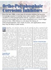
The new <strong>Hillery</strong> <strong>Street</strong> <strong>Bridge</strong> replaces the original, built in1898. The original was a four-span, simply supported, rivetedPratt Pony Truss carrying one lane of traffic in each directionacross the Passaic River in northern New Jersey.North Jersey Transportation PlanningAuthority and the FHWA, agreed tohelp fund the replacement of the bridge.However, for Passaic County to receivethe funding, several features of the originalbridge would have to be preservedor replicated as per a memorandum ofagreement between the New Jersey StateHistoric Preservation Office and theFHWA.Integrating Existing Membersand Modern MaterialsThe new bridge is a four-span, multisteelbeam superstructure with a reinforcedconcrete deck slab. The width ofthe bridge deck was increased from 17 ftsix in. to 30 ft from curb to curb, andthe load carrying capacity increasedfrom three to 40 tons. The original fiveftsix-in. sidewalk width along each sideof the bridge was retained. Roadwayimprovementswere made toreduce the incidenceof trafficaccidents. Theseincluded correctionof the poorsite distance andsubstandard turningradii at theintersectionimmediately westof the bridge byflaring the westspan of the bridgeand adding trafficsignalization tothe intersection.The new bridge was designed in accordancewith the requirements of load andresistance factor design.The superstructure is composed ofpainted W36 steel beams (AASHTOM270 Gr. 50) continuous over the fourspans. The beams are spaced at seven fteight in. on center and have a nine-in.thick reinforced high-performance concretedeck slab. The flare of the westspan was accommodated by providingdiagonal beams, which frame into the“fascia” beams. The continuous structureeliminated the need for deck joints,thereby reducing the problems associatedwith leaking joints. Reinforced elastomericbearings were installed at theabutments and piers.Six original bridge trusses that were inthe best condition were reused on threeof the four spans. Each truss consisted ofvarious members (i.e., the top and bottomchords, verticals, and diagonals),which were, themselves, composed ofindividual components (i.e., angles andplates). Even though most of the individualcomponents were only 1/4 or5/16 of an inch thick, whereby only aminor amount of corrosion could significantlyreduce the cross sectional area,about half of the members were in goodenough condition to be retained. Theother half had to be replaced with newmembers that replicated the old ones.To preserve the remaining trusses aspart of the new bridge, they were integratedinto the structural framework ofthe superstructure. The cantileveredsidewalk brackets were connected togusset plates attached to the trusses inthe same manner they were connectedin the original bridge. The gusset plateswere then attached to the fascia beam.In this manner, members of the trussstill assist in providing some load-carryingcapability.To resist moment created by the sidewalkloads on the cantilevered sidewalkbrackets, W24 steel beams were used asdiaphragms, which transform themoment from the cantilevered sidewalkinto reactions, which were then resistedby the beams. To provide rigidity, theW24 diaphragms were used throughoutthe entire framing plan and not only inthe fascia bays.The cantilevered sidewalk brackets,which are mostly composed of doubleangle components, were replaced inkind,except the thickness of the angleswas increased from 1/4 in. to 3/8 in. tomeet current state requirements. TheAt left is a view of the sidewalk brackets and lower portion of the truss on the original <strong>Hillery</strong> <strong>Street</strong> <strong>Bridge</strong>. At right, a view of thenew cantilevered sidewalk brackets from the underside of the replacement bridge.18 ■ GOVERNMENT ENGINEERING ■ JANUARY-FEBRUARY 2010 www.govengr.com