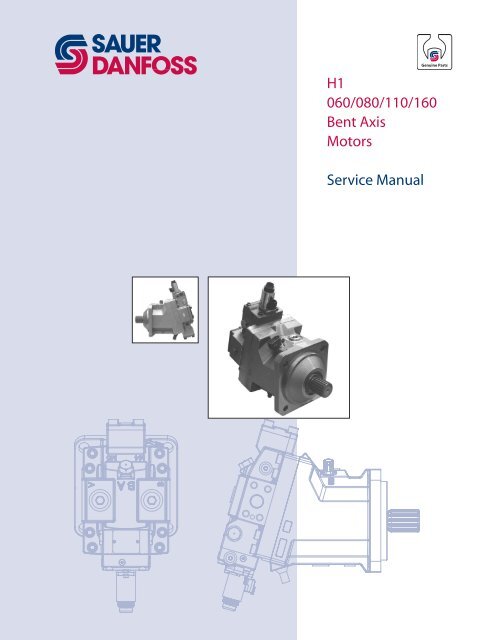
H1 060/080/110/160 Bent Axis Motors Service ... - Sauer-Danfoss
H1 060/080/110/160 Bent Axis Motors Service ... - Sauer-Danfoss
H1 060/080/110/160 Bent Axis Motors Service ... - Sauer-Danfoss

Create successful ePaper yourself
Turn your PDF publications into a flip-book with our unique Google optimized e-Paper software.
<strong>H1</strong><br />
<strong>060</strong>/<strong>080</strong>/<strong>110</strong>/<strong>160</strong><br />
<strong>Bent</strong> <strong>Axis</strong><br />
<strong>Motors</strong><br />
<strong>Service</strong> Manual
REVISION HISTORY<br />
<strong>H1</strong> <strong>060</strong>/<strong>080</strong>/<strong>110</strong>/<strong>160</strong> <strong>Bent</strong> <strong>Axis</strong> <strong>Motors</strong><br />
<strong>Service</strong> Manual<br />
Revisions<br />
Table of Revisions<br />
Date Page Changed Rev.<br />
2 <strong>110</strong>24924 • Rev BA • September 2012<br />
September 2012 all add <strong>160</strong> frame size BA<br />
January 2011 37 Port M4 is moved on control housing AJ<br />
November 2010 last new last page AI<br />
February 2010 last Fix Osaka address AH<br />
August 2009 various Minor corrections AG<br />
July 2009 11, 12, 15, 18 Updates to <strong>060</strong> technical specifications AF<br />
July 2009 35, 36 Coil O-rings are available with the purchase of a new coil AE<br />
April 2009 various added <strong>060</strong> frame size AD<br />
January 2009 33 2 position bolt torques are 115 Nm [85 lbf•ft] AC<br />
December 2008 various added <strong>080</strong> frame size AB<br />
Oct 2008 - First edition AA<br />
© 2012 <strong>Sauer</strong>-<strong>Danfoss</strong>. All rights reserved.<br />
<strong>Sauer</strong>-<strong>Danfoss</strong> accepts no responsibility for possible errors in catalogs, brochures and<br />
other printed material. <strong>Sauer</strong> -<strong>Danfoss</strong> reserves the right to alter its products without<br />
prior notice. This also applies to products already ordered, provided that such alterations<br />
can be made without affecting agreed specifications. All trademarks in this material<br />
are properties of their respective owners. <strong>Sauer</strong>-<strong>Danfoss</strong>, the <strong>Sauer</strong>-<strong>Danfoss</strong> logotype,<br />
the <strong>Sauer</strong>-<strong>Danfoss</strong> S-icon, PLUS+1, What really matters is inside® and Know-How in<br />
Motion are trademarks of the <strong>Sauer</strong>-<strong>Danfoss</strong> Group.
<strong>H1</strong> <strong>060</strong>/<strong>080</strong>/<strong>110</strong>/<strong>160</strong> <strong>Bent</strong> <strong>Axis</strong> <strong>Motors</strong><br />
<strong>Service</strong> Manual<br />
Contents<br />
INTRODUCTION Overview ........................................................................................................................................................... 5<br />
Warranty ............................................................................................................................................................ 5<br />
General instructions ...................................................................................................................................... 5<br />
Safety precautions ......................................................................................................................................... 6<br />
Unintended machine movement ....................................................................................................... 6<br />
Flammable cleaning solvents ............................................................................................................... 6<br />
Fluid under pressure ................................................................................................................................ 6<br />
Personal safety ........................................................................................................................................... 6<br />
Hazardous material .................................................................................................................................. 6<br />
Symbols used in <strong>Sauer</strong>-<strong>Danfoss</strong> literature ............................................................................................. 7<br />
GENERAL INFORMATION Design ................................................................................................................................................................ 8<br />
Overview .........................................................................................................................................................10<br />
System diagram ............................................................................................................................................11<br />
<strong>H1</strong>P pump and <strong>H1</strong> motor with electric proportional control .................................................11<br />
System schematic .........................................................................................................................................12<br />
OPERATION Shaft rotation direction ..............................................................................................................................13<br />
Loop flushing shuttle spool ......................................................................................................................14<br />
Loop flushing relief valve ..........................................................................................................................14<br />
Speed sensor ..................................................................................................................................................15<br />
Speed sensor connector .......................................................................................................................15<br />
Sensor position ........................................................................................................................................15<br />
Target ring .................................................................................................................................................15<br />
Minimum displacement limiter .........................................................................................................15<br />
OPERATING<br />
PARAMETERS<br />
TECHNICAL<br />
SPECIFICATIONS<br />
FLUID AND FILTER<br />
MAINTENANCE<br />
Overview .........................................................................................................................................................16<br />
Output speed .................................................................................................................................................16<br />
Start speed and low speed stability .................................................................................................16<br />
System pressure ............................................................................................................................................16<br />
Case pressure .................................................................................................................................................17<br />
External shaft seal pressure ......................................................................................................................17<br />
Temperature and viscosity ........................................................................................................................17<br />
Temperature .............................................................................................................................................17<br />
Viscosity......................................................................................................................................................17<br />
Technical specifications .............................................................................................................................18<br />
General specifications ...........................................................................................................................18<br />
Physical properties .................................................................................................................................18<br />
Operating parameters ...........................................................................................................................19<br />
Fluid specifications .................................................................................................................................19<br />
Fluid and filter recommendations ..........................................................................................................20<br />
<strong>110</strong>24924 • Rev BA • September 2012<br />
3
PRESSURE<br />
MEASUREMENTS<br />
INITIAL STARTUP<br />
PROCEDURES<br />
<strong>H1</strong> <strong>060</strong>/<strong>080</strong>/<strong>110</strong>/<strong>160</strong> <strong>Bent</strong> <strong>Axis</strong> <strong>Motors</strong><br />
<strong>Service</strong> Manual<br />
Contents<br />
Port locations and gauge installation ...................................................................................................21<br />
Procedure ........................................................................................................................................................22<br />
TROUBLESHOOTING Overview .........................................................................................................................................................24<br />
Electrical troubleshooting .........................................................................................................................24<br />
Sluggish operation ......................................................................................................................................24<br />
System operating hot .................................................................................................................................25<br />
Excessive noise or vibration ......................................................................................................................25<br />
Motor operates normally in one direction only ................................................................................25<br />
Improper output speed .............................................................................................................................26<br />
Low output torque .......................................................................................................................................26<br />
REQUIRED TOOLS AND<br />
STANDARD PROCEDURES<br />
Required tools ...............................................................................................................................................27<br />
Standard procedures ..................................................................................................................................27<br />
ADJUSTMENTS Displacement limiter ...................................................................................................................................28<br />
Adjusting the minimum displacement limiter .............................................................................28<br />
Optional threshold adjustment - proportional controls ................................................................29<br />
Adjusting threshold on test stand ....................................................................................................29<br />
Adjusting threshold on a machine or test stand without flow meter .................................29<br />
Pressure Compensator OverRide (PCOR) adjustment .....................................................................30<br />
PCOR adjustment for T1/T2 controls ................................................................................................30<br />
Brake pressure defeat option .............................................................................................................30<br />
PCOR adjustment for P1/P2 controls ...............................................................................................30<br />
MINOR REPAIR Shaft seal .........................................................................................................................................................31<br />
Solenoid replacement ................................................................................................................................32<br />
Control module replacement ..................................................................................................................33<br />
Proportional control module ...................................................................................................................34<br />
Two-position control module ..................................................................................................................36<br />
Maximum displacement limiter - two-position control .................................................................37<br />
Servo piston cover – proportional control ..........................................................................................38<br />
Replace speed sensor .................................................................................................................................39<br />
Loop flushing spool .....................................................................................................................................40<br />
Loop flushing charge relief valve ............................................................................................................41<br />
Minimum displacement limiter ...............................................................................................................42<br />
TORQUE CHART Fasteners and plugs .....................................................................................................................................43<br />
Fastener size and torque chart ................................................................................................................43<br />
Plug size and torque chart ........................................................................................................................43<br />
4 <strong>110</strong>24924 • Rev BA • September 2012
OVERVIEW<br />
GENERAL INSTRUCTIONS<br />
<strong>H1</strong> <strong>060</strong>/<strong>080</strong>/<strong>110</strong>/<strong>160</strong> <strong>Bent</strong> <strong>Axis</strong> <strong>Motors</strong><br />
<strong>Service</strong> Manual<br />
Introduction<br />
This manual includes information for the installation, maintenance, and minor repair<br />
of the <strong>H1</strong> bent-axis motor. It includes a description of the unit and its individual<br />
components, troubleshooting information, and minor repair procedures.<br />
Performing minor repairs may require removal from the vehicle/machine. Thoroughly<br />
clean the unit before beginning maintenance or repair activities. Since dirt and<br />
contamination are the greatest enemies of any type of hydraulic equipment, follow<br />
cleanliness requirements strictly. This is especially important when changing the system<br />
filter and when removing hoses or plumbing.<br />
A worldwide network of <strong>Sauer</strong>-<strong>Danfoss</strong> Global <strong>Service</strong> Partners is available for major<br />
repair. <strong>Sauer</strong>-<strong>Danfoss</strong> trains and certifies Global <strong>Service</strong> Partners on a regular basis. You<br />
can locate your nearest Global <strong>Service</strong> Partner using the distributor locator at<br />
www.sauer-danfoss.com. Click on the Sales and <strong>Service</strong> link.<br />
WARRANTY Performing installation, maintenance, and minor repairs according to the procedures in<br />
this manual will not affect your warranty. Major repairs requiring the removal of a unit’s<br />
rear cover voids the warranty unless done by a <strong>Sauer</strong>-<strong>Danfoss</strong> Global <strong>Service</strong> Partner.<br />
Follow these general procedures when repairing <strong>H1</strong> variable displacement closed circuit<br />
motors.<br />
w Remove the unit<br />
Chock the wheels on the vehicle or lock the mechanism to inhibit movement. Prior to<br />
performing repairs, remove the unit from the vehicle/machine. Be aware that hydraulic<br />
fluid may be under high pressure and/or hot. Inspect the outside of the motor and<br />
fittings for damage. Cap hoses after removal to prevent contamination.<br />
e Keep it clean<br />
Cleanliness is a primary means of assuring satisfactory motor life, on either new or<br />
repaired units. Clean the outside of the motor thoroughly before disassembly. Take care<br />
to avoid contamination of the system ports. Cleaning parts with a clean solvent wash<br />
and air drying is usually adequate.<br />
Keep all parts free of foreign materials and chemicals. Protect all exposed sealing<br />
surfaces and open cavities from damage and foreign material. If left unattended, cover<br />
the motor with a protective layer of plastic.<br />
d Replace all O-rings and gaskets<br />
<strong>Sauer</strong>-<strong>Danfoss</strong> recommends you replace all O-rings and gaskets during repair. Lightly<br />
lubricate O-rings with clean petroleum jelly prior to assembly.<br />
t Secure the unit<br />
For repair, place the unit in a stable position with the shaft pointing downward. Secure<br />
the motor while removing and torquing components and fasteners.<br />
<strong>110</strong>24924 • Rev BA • September 2012<br />
5
<strong>H1</strong> <strong>060</strong>/<strong>080</strong>/<strong>110</strong>/<strong>160</strong> <strong>Bent</strong> <strong>Axis</strong> <strong>Motors</strong><br />
<strong>Service</strong> Manual<br />
Introduction<br />
SAFETY PRECAUTIONS Always consider safety precautions before beginning a service procedure. Protect<br />
yourself and others from injury. Take the following general precautions whenever servicing a<br />
hydraulic system.<br />
Unintended machine movement<br />
W Warning<br />
Unintended movement of the machine or mechanism may cause injury to the technician<br />
or bystanders. To protect against unintended movement, secure the machine or disable/<br />
disconnect the mechanism while servicing.<br />
Flammable cleaning solvents<br />
W Warning<br />
Some cleaning solvents are flammable. To avoid possible fire, do not use cleaning<br />
solvents in an area where a source of ignition may be present.<br />
Fluid under pressure<br />
W Warning<br />
Escaping hydraulic fluid under pressure can have sufficient force to penetrate your skin<br />
causing serious injury and/or infection. This fluid may also be hot enough to cause burns.<br />
Use caution when dealing with hydraulic fluid under pressure. Relieve pressure in the<br />
system before removing hoses, fittings, gauges, or components. Never use your hand<br />
or any other body part to check for leaks in a pressurized line. Seek medical attention<br />
immediately if you are cut by hydraulic fluid.<br />
Personal safety<br />
W Warning<br />
Protect yourself from injury. Use proper safety equipment, including safety glasses, at all<br />
times.<br />
Hazardous material<br />
W Warning<br />
Hydraulic fluid contains hazardous material. Avoid prolonged contact with hydraulic<br />
fluid. Always dispose of used hydraulic fluid according to environmental regulations.<br />
6 <strong>110</strong>24924 • Rev BA • September 2012
SYMBOLS USED IN<br />
SAUER-DANFOSS<br />
LITERATURE<br />
<strong>H1</strong> <strong>060</strong>/<strong>080</strong>/<strong>110</strong>/<strong>160</strong> <strong>Bent</strong> <strong>Axis</strong> <strong>Motors</strong><br />
<strong>Service</strong> Manual<br />
Introduction<br />
� WARNING may result in injury<br />
� CAUTION may result in damage to<br />
product or property<br />
� Non-reusable part, use a new part<br />
� Option – either part may exist<br />
� External hex head<br />
<strong>110</strong>24924 • Rev BA • September 2012<br />
� Internal hex head<br />
� Lubricate with hydraulic fluid<br />
� Clean area or part<br />
� Mark orientation for reinstallation<br />
� Torque specification<br />
� Cover splines with installation<br />
sleeve<br />
The symbols above appear in the illustrations and text of this manual. They are intended<br />
to communicate helpful information at the point where it is most useful to the reader.<br />
In most instances, the appearance of the symbol itself denotes its meaning. The legend<br />
above defines each symbol and explains its purpose.<br />
7
DESIGN<br />
Ramp spring<br />
Loop flushing<br />
shuttle spool<br />
Loop flushing<br />
relief valve<br />
<strong>H1</strong> <strong>060</strong>/<strong>080</strong>/<strong>110</strong>/<strong>160</strong> <strong>Bent</strong> <strong>Axis</strong> <strong>Motors</strong><br />
<strong>Service</strong> Manual<br />
General information<br />
Cross section <strong>H1</strong> with electric proportional control<br />
Electric proportional co ntrol<br />
8 <strong>110</strong>24924 • Rev BA • September 2012<br />
Di�erential<br />
servo piston<br />
Valve segment<br />
Bearing plate<br />
Minimum displacement limiter<br />
Tapered<br />
roller bearing<br />
Speed ring (optional )<br />
P003 421E
DESIGN<br />
Loop flushing<br />
shuttle spool<br />
Loop flushing<br />
relief valve<br />
<strong>H1</strong> <strong>060</strong>/<strong>080</strong>/<strong>110</strong>/<strong>160</strong> <strong>Bent</strong> <strong>Axis</strong> <strong>Motors</strong><br />
<strong>Service</strong> Manual<br />
General information<br />
Cross section <strong>H1</strong> electric two-position control<br />
<strong>110</strong>24924 • Rev BA • September 2012<br />
Electric two- position control<br />
Di�erential<br />
servo piston<br />
Valve segment<br />
Bearing plate<br />
Minimum displacement limiter<br />
Tapered<br />
roller bearing<br />
Speed ring (optional )<br />
P003 422E<br />
9
<strong>H1</strong> <strong>060</strong>/<strong>080</strong>/<strong>110</strong>/<strong>160</strong> <strong>Bent</strong> <strong>Axis</strong> <strong>Motors</strong><br />
<strong>Service</strong> Manual<br />
General information<br />
OVERVIEW <strong>H1</strong> variable displacement motors follow the bent-axis design using spherical pistons.<br />
These motors function primarily with other products in closed-circuit systems to transfer<br />
and control hydraulic power. <strong>H1</strong> motors have a large displacement ratio of 5:1 and high<br />
output speed capabilities. Zero-degree capability enables anti-slip and wheel-assist<br />
systems. SAE, cartridge, and DIN flange configurations with radial or axial high pressure<br />
ports and integral loop-flushing are also available.<br />
<strong>H1</strong>’s complete family of controls and regulators suit a wide range of applications. All<br />
controls use internally-supplied servo pressure. A Pressure Compensator OverRide<br />
(PCOR) feature is available to override the control increasing displacement at a set<br />
pressure threshold. The PCOR is available with a Brake Pressure Defeat (BPD) option to<br />
disable it during dynamic braking. The pressure compensator features a low pressure rise<br />
to ensure optimal power usage throughout the entire displacement range of the motor.<br />
Speed sensor options are available for all frame sizes and flange styles. They can sense<br />
speed, direction, and temperature; all in one compact package.<br />
All <strong>H1</strong> electric controls are PLUS+1 compliant. They are designed specifically to<br />
integrate with <strong>Sauer</strong>-<strong>Danfoss</strong> PLUS+1 microcontrollers for easy Plug-and-Perform<br />
installation.<br />
10 <strong>110</strong>24924 • Rev BA • September 2012
SYSTEM DIAGRAM<br />
Heat Exchanger<br />
Bypass Valve<br />
Reservoir<br />
<strong>H1</strong> <strong>060</strong>/<strong>080</strong>/<strong>110</strong>/<strong>160</strong> <strong>Bent</strong> <strong>Axis</strong> <strong>Motors</strong><br />
<strong>Service</strong> Manual<br />
General information<br />
<strong>H1</strong> pump and <strong>H1</strong> motor with electric proportional control<br />
Heat Exchanger<br />
Electric<br />
Displacement<br />
Control<br />
<strong>Bent</strong> <strong>Axis</strong> Variable<br />
Displacement Motor<br />
Loop<br />
Flushing<br />
Valve<br />
Charge Check/<br />
High Pressure<br />
Relief Valve<br />
Pressure Limiter<br />
Valve<br />
Servo Cylinder<br />
<strong>110</strong>24924 • Rev BA • September 2012<br />
Pump<br />
Swashplate<br />
Output<br />
Shaft<br />
Charge Pressure<br />
Filter<br />
To<br />
Motor<br />
Case<br />
Valve<br />
Segment<br />
Charge Check/<br />
High Pressure<br />
Relief Valve<br />
Charge<br />
Pump<br />
Input<br />
Shaft<br />
Charge<br />
Pressure<br />
Relief<br />
Valve<br />
Pressure Limiter Valve<br />
Variable<br />
Displacement<br />
Pump<br />
P003 423E<br />
Suction<br />
Servo<br />
Pressure<br />
Working Loop A (Low Pressure)<br />
and Charge Pressure<br />
Case<br />
Drain<br />
Working Loop B<br />
(High Pressure)<br />
11
SYSTEM SCHEMATIC<br />
M5<br />
M4<br />
F00B<br />
M14 M6<br />
C2 C1<br />
F00A<br />
<strong>H1</strong> <strong>060</strong>/<strong>080</strong>/<strong>110</strong>/<strong>160</strong> <strong>Bent</strong> <strong>Axis</strong> <strong>Motors</strong><br />
<strong>Service</strong> Manual<br />
General information<br />
12 <strong>110</strong>24924 • Rev BA • September 2012<br />
CW<br />
1 2<br />
R2<br />
R1<br />
S L3 L4<br />
max. 3 bar<br />
[43.5 psi]<br />
M3 L1 L2 MA<br />
MB<br />
A<br />
B<br />
A<br />
B<br />
L2 MA N<br />
max.<br />
M4<br />
min.<br />
M5 MB<br />
n<br />
L1<br />
P003 424E<br />
This schematic shows the function of a hydrostatic transmission using an <strong>H1</strong>P axial<br />
variable displacement pump with electric proportional displacement control (EDC) and<br />
an <strong>H1</strong> bent axis variable displacement motor with electric proportional control (L*) and<br />
integrated loop flushing device.
SHAFT ROTATION<br />
DIRECTION<br />
<strong>H1</strong> <strong>060</strong>/<strong>080</strong>/<strong>110</strong>/<strong>160</strong> <strong>Bent</strong> <strong>Axis</strong> <strong>Motors</strong><br />
<strong>Service</strong> Manual<br />
Operation<br />
Shaft rotation direction is determined by viewing the shaft end. Rotation direction of the<br />
motor is dependent on the control option as the drawing and table below illustrate.<br />
Control Option L<br />
Control Option M and K<br />
Control Option E, P, and T<br />
<strong>110</strong>24924 • Rev BA • September 2012<br />
CCW CW<br />
Port B Port A<br />
CCW CW<br />
Port A Port B<br />
CCW CW<br />
Port A Port B<br />
P003488<br />
Position of control Flow into port Direction of rotation<br />
Control options L*<br />
Control options M*, K*, E*, P* and T*<br />
A CW<br />
B CCW<br />
A CCW<br />
B CW<br />
13
LOOP FLUSHING<br />
SHUTTLE SPOOL<br />
LOOP FLUSHING RELIEF<br />
VALVE<br />
<strong>H1</strong> <strong>060</strong>/<strong>080</strong>/<strong>110</strong>/<strong>160</strong> <strong>Bent</strong> <strong>Axis</strong> <strong>Motors</strong><br />
<strong>Service</strong> Manual<br />
Operation<br />
An integral loop flushing shuttle spool resolves low loop pressure and connects it to the<br />
loop flushing relief valve. The spool operates on delta pressure in the working loop.<br />
System<br />
loop A<br />
to Loop �ushing<br />
relief valve<br />
System<br />
loop B<br />
14 <strong>110</strong>24924 • Rev BA • September 2012<br />
P003 490E<br />
An orificed loop flushing relief valve<br />
controls the volume of fluid flushed from<br />
the working loop. Valves are available<br />
with several orifice sizes to meet varying<br />
flow requirements. All valves have a<br />
cracking pressure of 16 bar [232 psi].<br />
Loop flushing relief valve<br />
Low System Pressure minus Case Pressure<br />
bar [psi]<br />
40 [580]<br />
30 [435]<br />
20 [290]<br />
10 [145]<br />
0<br />
05<br />
10<br />
[1.3]<br />
Loop Flushing Relief Valve Size<br />
10 15<br />
20<br />
[5.3]<br />
30<br />
[8.0]<br />
40<br />
[10.6]<br />
50<br />
[13.3]<br />
60<br />
[15.9]<br />
Loop Flushing Flow l/min [US gal/min]<br />
P003 491<br />
70<br />
[18.6]<br />
P003494E<br />
A<br />
B<br />
A<br />
B<br />
L2<br />
P003 437<br />
L2<br />
P003 487
<strong>H1</strong> <strong>060</strong>/<strong>080</strong>/<strong>110</strong>/<strong>160</strong> <strong>Bent</strong> <strong>Axis</strong> <strong>Motors</strong><br />
<strong>Service</strong> Manual<br />
Operation<br />
SPEED SENSOR An optional speed sensor is available. It is capable of measuring speed, direction of<br />
rotation, and case oil temperature. The temperature sensor can not be used for dynamic<br />
measurement, however, it is excellent for diagnostics. The sensor requires no adjustment.<br />
Speed sensor technical data<br />
Feature Min. Nom. Max. Units<br />
Supply 4.75 5.00 5.25 Vdc<br />
Supply protection - - 30 Vdc<br />
Max. required<br />
supply current<br />
Output mode NPN & PNP<br />
Connector Deutsch DTM-Series 6-pin DTM 04 - 6P<br />
Connector terminals<br />
Protection code IP-class<br />
Speed sensor connector<br />
<strong>110</strong>24924 • Rev BA • September 2012<br />
P107 858E<br />
IP 67 and IP 69k according<br />
IEC 60529 & DIN 40050<br />
4<br />
5 6<br />
3 2 1<br />
25 mA<br />
Sensor Pinout<br />
1<br />
2<br />
3<br />
4<br />
5<br />
6<br />
Signal 2<br />
Direction<br />
Signal 1<br />
Supply<br />
Ground<br />
Temperature<br />
Description Quantity Ordering number<br />
Mating connector Deutsch DTM06-6P 1 <strong>110</strong>33865<br />
Sensor position<br />
SAE and DIN housing Cartridge housing<br />
Target ring<br />
P003450<br />
Target ring - frame size <strong>060</strong> <strong>080</strong> <strong>110</strong><br />
Number of teeth 71 78 86<br />
P003489<br />
Minimum Displacement Limiter<br />
Minimum displacement limiter<br />
<strong>H1</strong> motors incorporate mechanical displacement limiters. The minimum displacement of<br />
the motor is adjusted at the factory. A tamper-proof cap is provided.<br />
15
OVERVIEW<br />
OUTPUT SPEED<br />
SYSTEM PRESSURE<br />
<strong>H1</strong> <strong>060</strong>/<strong>080</strong>/<strong>110</strong>/<strong>160</strong> <strong>Bent</strong> <strong>Axis</strong> <strong>Motors</strong><br />
<strong>Service</strong> Manual<br />
Operating parameters<br />
This section defines the operating parameters and limitations for <strong>H1</strong> motors for output<br />
speeds, fluid pressures, temperature, and viscosity. For actual parameters, refer to<br />
Technical specifications, page 18.<br />
Start speed and low speed stability<br />
The motor produces maximum starting torque at maximum displacement. It achieves<br />
smooth operation at 15-25 min -1 (rpm) ± 5 %, depending on system pressure, in<br />
applications that require low speed stability. Motor output becomes smoother as speed<br />
increases.<br />
Rated speed is the highest output speed recommended at full power condition.<br />
Operating at or below this speed will yield satisfactory product life.<br />
Maximum speed is the highest operating speed permitted. Exceeding maximum speed<br />
reduces the product life and can cause loss of hydrostatic power and dynamic braking<br />
capacity. Never exceed the maximum speed limit under any operation conditions.<br />
Limit operating between rated speed and maximum speed to short time periods. For<br />
most drive systems, maximum unit speed occurs when the motor is in an overrunning<br />
condition, such as downhill, dynamic braking, or negative power conditions.<br />
For applications outside rated speed limits, please contact your <strong>Sauer</strong>-<strong>Danfoss</strong><br />
representative.<br />
W Warning<br />
Unintended vehicle or machine movement hazard.<br />
Exceeding maximum speed may cause a loss of hydrostatic driveline power and dynamic<br />
braking capacity. You must provide a braking system, redundant to the hydrostatic<br />
transmission, sufficient to stop and hold the vehicle or machine in the event of<br />
hydrostatic drive power loss.<br />
System pressure is the differential pressure between system ports. It is the dominant<br />
operating variable affecting hydraulic unit life. High system pressure, which results from<br />
high load, reduces expected life. Hydraulic unit life depends on the speed and normal<br />
operating—or weighted average—pressure that can only be determined from a duty<br />
cycle analysis.<br />
Application pressure is the high pressure relief or pressure limiter setting normally<br />
defined within the order code of the pump. This is the applied system pressure at which<br />
the driveline generates the maximum calculated pull or torque in the application.<br />
Maximum working pressure is the highest recommended application pressure.<br />
Maximum working pressure is not intended to be a continuous pressure. Propel systems<br />
with application pressures at, or below, this pressure should yield satisfactory unit life<br />
given proper component sizing.<br />
Maximum pressure is the highest allowable application pressure under any<br />
circumstance. For applications operating above the maximum working pressure, please<br />
contact your <strong>Sauer</strong>-<strong>Danfoss</strong> representative.<br />
16 <strong>110</strong>24924 • Rev BA • September 2012
SYSTEM PRESSURE<br />
(continued)<br />
CASE PRESSURE<br />
EXTERNAL SHAFT SEAL<br />
PRESSURE<br />
TEMPERATURE AND<br />
VISCOSITY<br />
<strong>H1</strong> <strong>060</strong>/<strong>080</strong>/<strong>110</strong>/<strong>160</strong> <strong>Bent</strong> <strong>Axis</strong> <strong>Motors</strong><br />
<strong>Service</strong> Manual<br />
Operating parameters<br />
All pressure limits are differential pressures referenced to low loop (charge) pressure.<br />
Subtract low loop pressure from high loop gauge readings to compute the differential.<br />
You must maintain minimum pressure under all operating conditions to avoid<br />
cavitation.<br />
Summing pressure is the sum of both the low and high loop pressures.<br />
Servo pressure is the pressure in the servo system and is supplied from the high side of<br />
the loop to keep the motor at the required displacement.<br />
Under normal operating conditions case pressure must not exceed its rated limit. During<br />
cold start, case pressure must remain below maximum intermittent case pressure. Size<br />
drain plumbing accordingly.<br />
CCaution<br />
Possible component damage or leakage.<br />
Operation with case pressure in excess of stated limits may damage seals, gaskets, and/<br />
or housings, causing external leakage. This may also affect performance since charge and<br />
system pressure is referenced to case pressure.<br />
In certain applications, the output shaft seal may be exposed to external pressures. The<br />
shaft seal is designed to withstand an external pressure up to 0.25 bar [3.6 psi] above<br />
the case pressure. The case pressure must also remain within limits to prevent shaft seal<br />
damage.<br />
Temperature<br />
The high temperature limits apply at the hottest point in the transmission, which is<br />
normally the motor case drain. The system should generally be run at or below the<br />
published rated temperature.<br />
The maximum intermittent temperature is based on material properties. Never exceed it.<br />
The minimum temperature relates to the physical properties of component materials.<br />
Cold oil will generally not affect the durability of the transmission components, but<br />
low temperature may affect the ability of oil to flow and transmit power. Therefore,<br />
temperatures should remain 16 °C [30 °F] above the pour point of the hydraulic fluid.<br />
Size heat exchangers too keep the fluid within prescribed limits. <strong>Sauer</strong>-<strong>Danfoss</strong><br />
recommends testing to verify that these temperature limits are not exceeded.<br />
Viscosity<br />
For maximum efficiency and bearing life, ensure that the fluid viscosity remains in the<br />
recommended range.<br />
The motor should encounter minimum viscosity only during brief periods of maximum<br />
ambient temperature and severe duty cycle operation. The motor should encounter<br />
maximum viscosity only at cold start.<br />
<strong>110</strong>24924 • Rev BA • September 2012<br />
17
TECHNICAL<br />
SPECIFICATIONS<br />
Physical properties<br />
<strong>H1</strong> <strong>060</strong>/<strong>080</strong>/<strong>110</strong>/<strong>160</strong> <strong>Bent</strong> <strong>Axis</strong> <strong>Motors</strong><br />
<strong>Service</strong> Manual<br />
Technical specifications<br />
Feature Unit Frame size<br />
18<br />
<strong>110</strong>24924 • Rev BA • September 2012<br />
<strong>060</strong> <strong>080</strong> <strong>110</strong> <strong>160</strong><br />
Displacement maximum cm 3 [in 3 ] 60 [3.66] 80 [4.88] <strong>110</strong> [6.71] <strong>160</strong> [9.76]<br />
Displacement minimum cm 3 [in 3 ] 12 [0.73] 16 [0.98] 22 [1.34] 32 [1.95]<br />
Flow at rated speed (theoretical) l/min [US gal/min] 216 [57] 256 [67] 319 [84] 416 [<strong>110</strong>]<br />
Flow at maximum speed (theoretical) l/min [US gal/min] 270 [71] 328 [86] 407 [107] 528 [139]<br />
Torque at maximum displacements<br />
(theoretical)<br />
Theoretical corner power at rated<br />
speed an maximum working<br />
pressure (Dp=450 bar [6527 psi])<br />
Mass moment of inertia of rotating<br />
components<br />
Weight dry with electric<br />
N•m/bar<br />
0.95 [583] 1.28 [784] 1.75 [1064] 2.55 [1563]<br />
[lbf•in/1000 psi]<br />
kW [hp] 266 [356] 306 [410] 396 [531] 513 [688]<br />
kg•m 2 [slug•ft 2 ] 0.0042 [0.0031] 0.0064 [0.0047] 0.0114 [0.0084] 0.0204 [0.0150]<br />
proportional control<br />
SAE configuration kg [lb] 29.8 [65.8] 34.9 [76.9] 48.8 [107.8] 61.9 [136.5]<br />
DIN configuration kg [lb] 28.3 [62.5] 34.4 [76.0] 45.0 [99.4] 59.3 [130.7]<br />
Cartridge configuration kg [lb] 26.9 58.4] 33.0 [72.8] 41.8 [92.3] 54.7 [120.6]<br />
Case volume liter [US gal] 0.9 [0.24] 1.0 [0.26] 1.4 [0.37] 2.7 [0.71]<br />
Mounting flange<br />
SAE configuration Flange 127-4 (SAE C) Flange 152-4 (SAE D)<br />
DIN configuration Flange 125 B4 HL<br />
4-bolt<br />
Cartridge configuration pilot dia. <strong>160</strong> mm<br />
Main port configuration<br />
2-bolt (200 dist.)<br />
M16<br />
Radial split flange boss DN19 typ. I 40Mpa<br />
Flange 140 B4 HL<br />
4-bolt<br />
pilot dia. 190 mm<br />
2-bolt (224 dist.)<br />
M20<br />
Flange <strong>160</strong> B4 HL<br />
4-bolt<br />
Flange 180 B4 HL<br />
4-bolt<br />
pilot dia. 200 mm 2-bolt (250 dist.) M20<br />
DN25 Typ I 40Mpa Series ISO 6162 DN32 Typ I 40Mpa<br />
series ISO 6162<br />
Series ISO 6162<br />
Axial SAE O-ring boss<br />
(Gauge port)<br />
0.875-14UN-2B<br />
[7/8 14UN- 2B]<br />
1.0625-12UN-2B [1 1/16 12UN-2B]<br />
Axial split flange boss DN19 typ. I 40Mpa<br />
series ISO 6162<br />
DN25 Typ I 40Mpa Series ISO 6162<br />
DN32 Typ I 40Mpa<br />
Series ISO 6162<br />
Gauge port SAE O-ring boss 0.5625-18UNF-2B [9/16-18UNF-2B]<br />
Case drain ports SAE O-ring boss 0.875-14UN-2B [7/8 14UN-2B] 1.0625-12UN-2B [1 1/16 12UN-2B]<br />
Gauge ports SAE O-ring boss 0.5625-18UNF-2B [9/16-18UNF-2B]<br />
Customer interface threads See installation<br />
General specifications<br />
Design Axial piston motor with variable displacement bent axis design<br />
Direction of rotation Bi-directional<br />
Pipe connections Main pressure ports: ISO split flange boss<br />
drawings in<br />
Technical<br />
Information<br />
Manual<br />
Remaining ports: SAE straight thread O-ring boss<br />
Recommended installation position Discretionary: The housing must always be filled with hydraulic fluid<br />
Metric fastener
TECHNICAL<br />
SPECIFICATIONS<br />
(continued)<br />
Operating parameters<br />
<strong>H1</strong> <strong>060</strong>/<strong>080</strong>/<strong>110</strong>/<strong>160</strong> <strong>Bent</strong> <strong>Axis</strong> <strong>Motors</strong><br />
<strong>Service</strong> Manual<br />
Technical specifications<br />
Feature Units Frame size<br />
Output speed<br />
System pressure<br />
Case pressure<br />
Rated<br />
Maximum<br />
Max. working pressure<br />
Maximum displacement 32°<br />
<strong>060</strong> <strong>080</strong> <strong>110</strong> <strong>160</strong><br />
3600 3200 2900 2600<br />
Minimum displacement 6° 5900 5100 4800 4250<br />
min-1 zero displacement 0° (rpm) 6600 5500 5350 4750<br />
Maximum displacement 32° 4500 4100 3700 3300<br />
Minimum displacement 6° 7000 6350 5950 5250<br />
zero displacement 0° 7600 6750 6500 5750<br />
450 [6527]<br />
Maximum pressure bar [psi]<br />
480 [6960]<br />
Minimum pressure 7.5 [109]<br />
Rated<br />
Fluid specifications<br />
Maximum bar [psi]<br />
5 [73]<br />
<strong>110</strong>24924 • Rev BA • September 2012 19<br />
3 [44]<br />
Minimum 0.3 [4]<br />
Feature Units<br />
Viscosity<br />
Temperature<br />
Range 1)<br />
Filtration<br />
(recommended minimum)<br />
Minimum<br />
mm2 7 [49]<br />
/sec<br />
Recommended range 12-80 [66-370]<br />
[SUS]<br />
Maximum <strong>160</strong>0 [7500]<br />
Minimum<br />
1) At the hottest point, normally case drain port.<br />
-40 [-40]<br />
Recommended range °C [°F]<br />
104 [220]<br />
Maximum 115 [240]<br />
Cleanliness per ISO 4406 22/18/13<br />
Efficiency (charge pressure filtration)<br />
Efficiency (suction and return line filtration)<br />
b-ratio<br />
b15-20=75 (b10≥10) b35-45=75 (b10≥2) Recommended inlet screen mesh size mm 100-125
FLUID AND FILTER<br />
RECOMMENDATIONS<br />
<strong>H1</strong> <strong>060</strong>/<strong>080</strong>/<strong>110</strong>/<strong>160</strong> <strong>Bent</strong> <strong>Axis</strong> <strong>Motors</strong><br />
<strong>Service</strong> Manual<br />
Fluid and filter maintenance<br />
To ensure optimum life, perform regular maintenance of the fluid and filter.<br />
Contaminated fluid is the main cause of unit failure. Take care to maintain fluid<br />
cleanliness when servicing.<br />
Check the reservoir daily for proper fluid level, the presence of water, and rancid fluid<br />
odor. Fluid contaminated by water may appear cloudy or milky or free water may<br />
settle in the bottom of the reservoir. Rancid odor indicates the fluid has been exposed<br />
to excessive heat. Change the fluid immediately if these conditions occur. Correct the<br />
problem immediately.<br />
Inspect vehicle for leaks daily.<br />
Change the fluid and filter per the<br />
vehicle/machine manufacturer’s<br />
recommendations or at these intervals.<br />
We recommend first fluid change occur<br />
at 500 hours of operation. Change the<br />
20 <strong>110</strong>24924 • Rev BA • September 2012<br />
Fluid and filter change interval<br />
Reservoir type Max oil change interval<br />
Sealed 2000 hours<br />
Breather 500 hours<br />
fluid more frequently if it becomes contaminated with foreign matter (dirt, water, grease,<br />
etc) or if the fluid is subjected to temperature levels greater than the recommended<br />
maximum.<br />
CCaution<br />
High temperatures and pressures accelerate fluid aging. This may require more frequent<br />
fluid changes.<br />
Change filters when changing fluid or when the filter indicator directs. Replace all fluid<br />
lost during filter change<br />
W Warning<br />
Hydraulic fluid contains hazardous material. Avoid contact with hydraulic fluid. Always<br />
dispose of used hydraulic fluid according to state, and federal environmental regulations.<br />
Never reuse hydraulic fluid.
MA<br />
<strong>H1</strong> <strong>060</strong>/<strong>080</strong>/<strong>110</strong>/<strong>160</strong> <strong>Bent</strong> <strong>Axis</strong> <strong>Motors</strong><br />
<strong>Service</strong> Manual<br />
Pressure measurements<br />
PORT LOCATIONS AND<br />
GAUGE INSTALLATION<br />
The following table and drawing show the port locations and gauge sizes needed.<br />
Port Information<br />
Port identifier<br />
Port size<br />
<strong>060</strong><br />
Wrench size Port size<br />
<strong>080</strong><br />
Wrench size Port size<br />
<strong>110</strong>/<strong>160</strong><br />
Wrench size<br />
Pressure<br />
obtained<br />
Gauge size,<br />
bar [psi]<br />
L1, L2 7/8-14 UNF 3/8 internal hex 7/8-14 UNF 3/8 internal hex 1 1/16 - 12UN 9/16 internal hex Case drain 10 [100]<br />
MA, MB 7/8-14 UNF 3/8 internal hex 1 1/16 - 12UN 9/16 internal hex 1 1/16 - 12UN 9/16 internal hex System 600 [10,000]<br />
(Radial endcap)<br />
pressure<br />
MA, MB 9/16-18 UNF 1/4 internal hex 9/16-18 UNF 1/4 internal hex 9/16-18 UNF 1/4 internal hex System 600 [10,000]<br />
(Axial endcap)<br />
pressure<br />
M4 9/16-18 UNF 1/4 internal hex 9/16-18 UNF 1/4 internal hex 9/16-18 UNF 1/4 internal hex Servo pressure<br />
rod end<br />
600 [10,000]<br />
M5 9/16-18 UNF 1/4 internal hex 9/16-18 UNF 1/4 internal hex 9/16-18 UNF 1/4 internal hex Servo pressure<br />
piston end<br />
600 [10,000]<br />
Port identifier<br />
System Ports<br />
<strong>060</strong><br />
Split flange boss, thread M12 x 1.75<br />
<strong>080</strong>, <strong>110</strong>, <strong>160</strong><br />
Split flange boss, thread M10 x 1.5<br />
A 3/4 inch code 62 per ISO 6162, min. thread 18mm [0.71 in] 1 inch code 62 per ISO 6162, min. thread 23mm [0.91 in]<br />
B 3/4 inch code 62 per ISO 6162, min. thread 18mm [0.71 in] 1 inch code 62 per ISO 6162, min. thread 23mm [0.91 in]<br />
Port locations - radial ported endcap shown<br />
L2<br />
MB<br />
Radial ported endcap<br />
<strong>110</strong>24924 • Rev BA • September 2012<br />
L1<br />
L2<br />
M5<br />
(M4 on reverse side)<br />
MA<br />
(MB on reverse side)<br />
System<br />
Port A<br />
Axial ported endcap<br />
M5<br />
(M4 on reverse side)<br />
System Port A<br />
(System Port B<br />
on reverse side)<br />
System<br />
Port B<br />
P106 623E<br />
21
<strong>H1</strong> <strong>060</strong>/<strong>080</strong>/<strong>110</strong>/<strong>160</strong> <strong>Bent</strong> <strong>Axis</strong> <strong>Motors</strong><br />
<strong>Service</strong> Manual<br />
Initial startup procedures<br />
PROCEDURE Always follow this procedure when starting-up a new <strong>H1</strong> installation or when the motor<br />
has been removed.<br />
� Warning<br />
This service procedure<br />
may require disabling<br />
the vehicle / machine<br />
(raising the wheels off the<br />
ground, disconnecting<br />
work function) while<br />
performing, to prevent<br />
injury to the technician<br />
and bystanders. Take<br />
the necessary safety<br />
precautions.<br />
� Warning<br />
Do not start the prime<br />
mover unless the pump is<br />
in neutral position (swash<br />
plate at 0° angle). Take<br />
necessary precautions<br />
to prevent machine<br />
movement in case pump is<br />
actuated (in stroke) during<br />
initial start-up.<br />
1. Before installing the motor, inspect the units for possible damage incurred during<br />
shipping and handling.<br />
2. Make certain all system components (reservoir, hoses, valves, fittings, heat exchanger,<br />
and so forth) are clean before filling with fluid.<br />
3. Fill the reservoir with recommended hydraulic fluid. Pass this fluid through a 10<br />
micron (nominal, no bypass) filter before it enters the reservoir.<br />
4. Fill the inlet line leading from the reservoir to the pump.<br />
5. Check inlet line for properly tightened fittings. Make sure the inlet line is free of<br />
restrictions and air leaks.<br />
6. Fill the motor and pump housings with clean hydraulic fluid before start up. Fill by<br />
pouring filtered oil into the upper case drain port.<br />
� Caution<br />
Never start the prime mover unless the motor and pump housings are filled completely<br />
with clean hydraulic fluid.<br />
7. For closed loop systems, install a 0-60 bar [0-1000 psi] pressure gauge in the charge<br />
pressure gauge port of the pump to monitor the charge pressure during start-up.<br />
For open circuit systems, use gauges in system ports.<br />
8. Disconnect any external control input signal from the pump control until after initial<br />
start-up. This ensures that the pump remains in its neutral position.<br />
9. Jog (slowly rotate) prime mover until charge pressure starts to rise.<br />
10. Start the prime mover and run at the lowest possible speed until charge pressure<br />
builds. �<br />
If necessary, bleed excess air from the high pressure lines through the high pressure<br />
system gauge ports.<br />
11. Once charge pressure is established, increase to normal operating speed. Charge<br />
pressure should be as indicated in the pump model code. If charge pressure is low,<br />
shut down and determine cause.<br />
� Caution<br />
Low charge pressure may affect ability to control the machine.<br />
22 <strong>110</strong>24924 • Rev BA • September 2012
PROCEDURE (continued)<br />
<strong>H1</strong> <strong>060</strong>/<strong>080</strong>/<strong>110</strong>/<strong>160</strong> <strong>Bent</strong> <strong>Axis</strong> <strong>Motors</strong><br />
<strong>Service</strong> Manual<br />
Initial startup procedures<br />
12. Shut down the prime mover.<br />
13. Connect the external control input signal.<br />
14. Reconnect the machine function if disconnected earlier.<br />
15. Start the prime mover, checking to ensure the pump remains in neutral.<br />
16. Check for forward and reverse machine operation, with the prime mover at<br />
normal operating speed.<br />
Charge pressure may decrease slightly during forward or reverse operation.<br />
17. Continue to cycle slowly between forward and reverse for at least five minutes.<br />
18. Shut down prime mover.<br />
19. Remove gauges. Replace plugs at the gauge ports.<br />
20. Check reservoir level. Add filtered fluid if needed.<br />
The motor/transmission is now ready for operation.<br />
<strong>110</strong>24924 • Rev BA • September 2012<br />
23
OVERVIEW<br />
ELECTRICAL TROUBLESHOOTING<br />
<strong>H1</strong> <strong>060</strong>/<strong>080</strong>/<strong>110</strong>/<strong>160</strong> <strong>Bent</strong> <strong>Axis</strong> <strong>Motors</strong><br />
<strong>Service</strong> Manual<br />
Troubleshooting<br />
This section provides general steps to follow if you observe undesirable system<br />
conditions. Follow the steps until you solve the problem. Some of the items are system<br />
specific. Always observe the safety precautions in the Introduction section, page 6.<br />
Item Description Action<br />
Motor operates at one<br />
displacement only.<br />
Control coil failure Measure resistance at coil pins.<br />
24 <strong>110</strong>24924 • Rev BA • September 2012<br />
Proportional controls: Resistance should be 14.20 Ohms (24V) or<br />
3.66 Ohms (12V) at 20°C [70°F].<br />
Two-position controls: Resistance should be 8.4 Ohms (24V) or<br />
34.5 Ohms (12V) at 20°C [70°F].<br />
Replace coil if necessary.<br />
Erratic motor function Electrical connection to motor is intermittent. Disconnect connector, check wires and terminals, reconnect wires.<br />
SLUGGISH OPERATION<br />
W Warning<br />
Unintended movement of the machine or mechanism may cause injury to the technician<br />
or bystanders. To protect against unintended movement, secure the machine or disable/<br />
disconnect the mechanism while servicing.<br />
Check terminals for corrosion and correct position.<br />
Check Cause Corrective action<br />
1. Control orifices Blocked or restricted orifice may cause sluggish<br />
2. Threshold setting (proportional<br />
controls)<br />
response. Orifices installed in the wrong<br />
locations may cause PCOR control to be sluggish.<br />
Inappropriately high or low threshold setting<br />
may shift the motor at the wrong time.<br />
3. Control spool A sticky control may cause sluggish response or<br />
no response.<br />
4. Pressure compensator setting Low pressure compensator setting may shift<br />
motor to maximum displacement at lower<br />
pressure.<br />
5. Control input signal An improper or erratic input signal to the control<br />
may cause sluggish response.<br />
6. Internal leakage Excessive leakage will cause lower charge<br />
pressure and affect performance.<br />
Remove, inspect and clean all orifices. Ensure the<br />
appropriate orifices are installed and in the correct<br />
location.<br />
Check threshold setting. Adjust if necessary.<br />
Clean and inspect the control spool. Replace if<br />
necessary.<br />
Check pressure compensator setting. Adjust if<br />
necessary.<br />
Check input signal and correct if necessary.<br />
Install loop flushing defeat option and measure<br />
case flow. If case flow is excessive, motor may<br />
require major repair. Contact your <strong>Sauer</strong>-<strong>Danfoss</strong><br />
authorized service center.
SYSTEM OPERATING HOT<br />
<strong>H1</strong> <strong>060</strong>/<strong>080</strong>/<strong>110</strong>/<strong>160</strong> <strong>Bent</strong> <strong>Axis</strong> <strong>Motors</strong><br />
<strong>Service</strong> Manual<br />
Troubleshooting<br />
Check Cause Corrective action<br />
1. Oil level Insufficient hydraulic fluid may cause<br />
overheating.<br />
2. Heat exchanger Blocked heat exchanger or low air flow may<br />
cause system overheating.<br />
3. Loop flushing flow Restricted orifice in loop flushing cartridge<br />
reduces flow.<br />
4. Loop flushing shuttle Loop flushing shuttle may be sticking in one<br />
direction.<br />
<strong>110</strong>24924 • Rev BA • September 2012<br />
Fill reservoir to proper level.<br />
Check temperature upstream and downstream<br />
of heat exchanger. Clean, repair, or replace heat<br />
exchanger if necessary.<br />
Measure case drain flow. Clean or replace orifice<br />
cartridge.<br />
Ensure shuttle moves freely in its bore.<br />
5. Air in system Entrained air generates heat under pressure Look for foam or bubbles in reservoir. Check for<br />
6. Internal leakage Excessive internal leakage may overheat the<br />
EXCESSIVE NOISE OR VIBRATION<br />
system.<br />
leaks on inlet side of charge pump.<br />
Install loop flushing defeat option and monitor<br />
case flow. If case flow is excessive, motor may<br />
require major repair. Contact your <strong>Sauer</strong>-<strong>Danfoss</strong><br />
authorized service center.<br />
Check Cause Corrective action<br />
1. Oil level in reservoir Insufficient hydraulic fluid may cause cavitation. Fill reservoir to proper level.<br />
2. Air in system Air bubbles may lead to cavitation. Look for foam or bubbles in reservoir. Check for<br />
leaks on inlet side of charge pump.<br />
3. Shaft coupling Loose shaft coupling may create excess noise. Replace loose shaft coupling. Replace or repair<br />
4. Shaft alignment Misaligned shafts may create excessive noise and<br />
vibration and can damage motor.<br />
MOTOR OPERATES NORMALLY IN ONE DIRECTION ONLY<br />
motor if shaft splines show excessive wear.<br />
Correct shaft misalignment.<br />
Check Cause Corrective action<br />
1. Charge pressure If charge pressure is low in one direction, the<br />
loop flushing shuttle spool may be sticking to<br />
one side.<br />
2. Pressure compensator control If pressure compensator operates in one<br />
direction only, the motor may stay at minimum<br />
displacement in the opposite direction.<br />
Measure charge pressure in forward and reverse. If<br />
pressure drops significantly lower in one direction,<br />
inspect and repair loop flushing shuttle spool.<br />
Check brake pressure defeat spool. It may be<br />
sticking or receiving an improper signal. Repair<br />
spool or correct input signal.<br />
25
IMPROPER OUTPUT SPEED<br />
<strong>H1</strong> <strong>060</strong>/<strong>080</strong>/<strong>110</strong>/<strong>160</strong> <strong>Bent</strong> <strong>Axis</strong> <strong>Motors</strong><br />
<strong>Service</strong> Manual<br />
Troubleshooting<br />
Check Cause Corrective action<br />
1. Oil level in reservoir Insufficient hydraulic fluid may reduce system<br />
efficiency.<br />
2. Threshold setting Improper threshold setting may cause motor to<br />
have wrong displacement for given signal.<br />
3. Pressure compensator setting Improper pressure compensator setting may<br />
shift motor displacement at wrong pressure.<br />
4. PC spool Pressure compensator spool sticking may shift<br />
motor to improper displacement.<br />
5. Control orifices Blocked or restricted orifice may cause motor to<br />
shift improperly.<br />
6. Control spool Sticky proportional control spool may cause<br />
motor to shift improperly.<br />
7. Control input signal Improper input signal may cause motor to shift<br />
improperly.<br />
8. Internal leakage Excess internal leakage may cause lower<br />
LOW OUTPUT TORQUE<br />
charge pressure and affect motor performance<br />
including output speed.<br />
26 <strong>110</strong>24924 • Rev BA • September 2012<br />
Fill reservoir to proper level.<br />
Check threshold setting. Refer to Control <strong>Service</strong><br />
Manual for adjustment procedure.<br />
Check pressure compensator setting. Adjust if<br />
necessary. Refer to Control <strong>Service</strong> Manual for<br />
adjustment procedure.<br />
Check pressure compensator spool. Repair or<br />
replace if needed. Refer to Control <strong>Service</strong> Manual<br />
for adjustment procedure.<br />
Remove, inspect and clean all orifices.<br />
Check control spool for proper operation. Repair if<br />
necessary. Refer to control adjustment procedure.<br />
Correct control input signal.<br />
Install loop flushing defeat option and measure<br />
case flow. If case flow is excessive, motor may<br />
require major repair. Contact your <strong>Sauer</strong>-<strong>Danfoss</strong><br />
authorized service center.<br />
Check Cause Corrective action<br />
1. Pressure compensator setting High pressure compensator setting may cause<br />
improper motor displacement for torque<br />
required.<br />
2. Control orifices Blocked or restricted orifice may cause motor to<br />
shift improperly.<br />
3. Pressure compensator spool Sticking pressure compensator spool may cause<br />
control to hold motor at minimum displacement.<br />
4. Control spool Sticking control spool may cause motor to shift<br />
improperly.<br />
5. Two position solenoid Two position control not shifting motor to<br />
maximum displacement.<br />
6. Control input signal Improper control input signal may cause motor<br />
7. Threshold setting<br />
(proportional control)<br />
to stay at minimum displacement.<br />
Improper threshold setting may cause improper<br />
motor displacement for torque required.<br />
8. Internal leakage Excess internal leakage may cause charge<br />
pressure to decay, reducing output torque.<br />
Check and adjust pressure compensator setting.<br />
Remove, inspect and clean all orifices.<br />
Remove and inspect pressure compensating spool.<br />
Repair or replace control if necessary.<br />
Remove and inspect control spool. Repair or replace<br />
control if necessary.<br />
Inspect solenoid valve for bent stem or damaged<br />
coil. Repair or replace if necessary.<br />
Correct control input signal.<br />
Check and adjust threshold setting.<br />
Install loop flushing defeat option and monitor<br />
case flow. If case flow is excessive, motor may<br />
require major repair. Contact your <strong>Sauer</strong>-<strong>Danfoss</strong><br />
authorized service center.
REQUIRED TOOLS<br />
STANDARD PROCEDURES<br />
C Caution<br />
Be careful not to damage<br />
solenoids and electrical<br />
connections when using<br />
straps or chains to remove<br />
motor from machine.<br />
<strong>H1</strong> <strong>060</strong>/<strong>080</strong>/<strong>110</strong>/<strong>160</strong> <strong>Bent</strong> <strong>Axis</strong> <strong>Motors</strong><br />
<strong>Service</strong> Manual<br />
Required tools and standard procedures<br />
The service procedures described in this manual can be performed using common<br />
mechanic’s hand tools. Special tools, if required, are shown. When testing system<br />
pressures, calibrate pressure gauges frequently to ensure accuracy. Use snubbers to<br />
protect gauges.<br />
C Caution<br />
Contamination can damage internal components and void the manufacturer’s warranty.<br />
Take precautions to ensure system cleanliness when removing and reinstalling system<br />
lines<br />
1. With the prime mover off, thoroughly clean all dirt and grime from the outside of the<br />
motor. Ensure the surrounding areas are clean and free of contaminants such as dirt<br />
and grime.<br />
2. If removing the motor, tag each hydraulic line connected to the motor. If you<br />
disconnect hydraulic lines, plug each open port to keep dirt and contamination out<br />
of the motor.<br />
3 Inspect the system for contamination. Look at the hydraulic fluid for signs of system<br />
contamination, such as oil discoloration, foam in the oil, sludge, or small metal<br />
particles.<br />
4. Remove the motor as a single unit. C<br />
5. Perform motor function test.<br />
6. Before re-installing the motor on the machine, drain the system, flush all lines,<br />
replace all filters, and fill with new hydraulic fluid.<br />
<strong>110</strong>24924 • Rev BA • September 2012<br />
27
MINIMUM<br />
DISPLACEMENT LIMITER<br />
<strong>H1</strong> <strong>060</strong>/<strong>080</strong>/<strong>110</strong>/<strong>160</strong> <strong>Bent</strong> <strong>Axis</strong> <strong>Motors</strong><br />
<strong>Service</strong> Manual<br />
Adjustments<br />
Adjusting the minimum displacement limiter<br />
1. Remove cap (N0120).<br />
Removing cap destroys the caps locking mechanism. Replace with new cap.<br />
2. Using a 6 mm internal hex wrench, hold adjusting screw (N0010) in place.<br />
3. Using a 19 mm hex wrench, loosen seal locknut (N0020).<br />
4. Turn adjusting screw clockwise to increase minimum displacement or<br />
counterclockwise to decrease minimum displacement. Minimum displacement is<br />
inversely related to maximum shaft speed. To increase maximum speed, decrease<br />
minimum displacement. Adjusting displacement limits also affects output torque.<br />
Refer to table for displacement change per turn.<br />
5. When properly adjusted, hold adjusting screw in place and torque seal locknut to<br />
45 N•m [32 lbf•ft].<br />
6. With motor on machine or test stand, verify correct motor function. Refer to Pressure<br />
measurements, page 21, for location of gauge ports and suggested gauge sizes.<br />
7. Install new cap (N0120).<br />
Minimum displacement limiter Displacement change per turn<br />
Model Displacement change<br />
<strong>160</strong> 4.7 cm3 [0.29 in3 ]<br />
<strong>110</strong> 3.3 cm3 [0.20 in3 ]<br />
<strong>080</strong> 2.7 cm3 [0.17 in3 ]<br />
<strong>060</strong> 2.1 cm3 [0.13 in3 ]<br />
19 mm<br />
45 N•m<br />
[32 lb•ft]<br />
N0020<br />
28 <strong>110</strong>24924 • Rev BA • September 2012<br />
N0010<br />
6 mm<br />
N0120<br />
P106 547E
OPTIONAL THRESHOLD<br />
ADJUSTMENT -<br />
PROPORTIONAL<br />
CONTROLS<br />
W Warning<br />
Unintended movement of<br />
the machine or mechanism<br />
may cause injury to the<br />
technician or bystanders.<br />
To protect against<br />
unintended movement,<br />
secure the machine<br />
or disable/disconnect<br />
the mechanism while<br />
servicing.<br />
<strong>H1</strong> <strong>060</strong>/<strong>080</strong>/<strong>110</strong>/<strong>160</strong> <strong>Bent</strong> <strong>Axis</strong> <strong>Motors</strong><br />
<strong>Service</strong> Manual<br />
Adjustments<br />
Adjusting threshold on test stand<br />
1. Connect flow meter to A or B system port. Refer to Port locations and gauge<br />
installation, page 21 for port locations.<br />
2. Connect solenoid to PWM signal generator at 100 Hz.<br />
Threshold is the electric signal when the motor starts to change from maximum to<br />
minimum displacement.<br />
3. Run prime mover at operating speed.<br />
Threshold adjustment<br />
<strong>110</strong>24924 • Rev BA • September 2012<br />
adjusting<br />
screw<br />
3 mm<br />
E101 548E<br />
B0040<br />
4. Adjust PWM signal to current listed in model code. Note flow reading.<br />
5. If adjustment is necessary, remove cap (B0040). Using a 3mm internal hex wrench,<br />
turn adjusting screw clockwise or counterclockwise until flow starts to change from<br />
maximum. Test your adjustment by lowering the current, then increasing the current<br />
until the displacement starts to change. Readjust the setting if necessary.<br />
6. When threshold is adjusted correctly, stop prime mover, install cap (B0040), and<br />
install motor on vehicle. Run vehicle and test for proper motor operation.<br />
Adjusting threshold on a machine or test stand without flow meter<br />
1. Install 600 bar [10,000 psi] gauges to ports M5 and M4. Connect solenoid to PWM<br />
signal.<br />
2. Raise wheels off ground, or disconnect the work function. W<br />
3. Run prime mover at operating speed. Stroke the pump to get some rotation of<br />
motor shaft.<br />
4. Increase signal current until M4 pressure becomes 1/2 of the M5 pressure. Check the<br />
signal current at this point.<br />
5. If adjustment is necessary, remove cap (B0040). Turn the adjusting screw until the<br />
signal current matches the model code setting.<br />
6. When threshold is adjusted correctly, stop prime mover, install cap. Run vehicle and<br />
test for proper motor operation.<br />
7. Remove from test stand.<br />
29
PRESSURE<br />
COMPENSATOR<br />
OVERRIDE (PCOR)<br />
ADJUSTMENT<br />
W Warning<br />
Unintended movement of<br />
the machine or mechanism<br />
may cause injury to the<br />
technician or bystanders.<br />
To protect against<br />
unintended movement,<br />
secure the machine<br />
or disable/disconnect<br />
the mechanism while<br />
servicing.<br />
<strong>H1</strong> <strong>060</strong>/<strong>080</strong>/<strong>110</strong>/<strong>160</strong> <strong>Bent</strong> <strong>Axis</strong> <strong>Motors</strong><br />
<strong>Service</strong> Manual<br />
Adjustments<br />
PCOR adjustment for T1/T2 controls<br />
1. With motor on vehicle, block wheels so vehicle can’t move.<br />
2. Install 600 bar [10,000 psi] gauges at servo pressure ports M4.<br />
3. With coil de-energised;<br />
4. Run prime mover at normal operating speed.<br />
5. Gradually increase system pressure until pressure at M4 drops.<br />
The highest system pressure before M4 drops is the PCOR setting.<br />
6. Use a 3 mm internal hex to hold the PCOR adjusting screw in place. Use a 10 mm<br />
wrench to loosen the PCOR locknut.<br />
30 <strong>110</strong>24924 • Rev BA • September 2012<br />
Locknut<br />
Adjusting screw<br />
P106 723E<br />
7. Turn the adjusting screw until system pressure is set to the PCOR setting specified<br />
in the model code. Decrease, then increase the system pressure to verify the PCOR<br />
setting. Retorque PCOR locknut.<br />
10 mm<br />
8. Shut down prime mover. Remove gauges and PWM signal generator. Reconnect<br />
electrical signal to solenoid.<br />
Brake pressure defeat option<br />
No adjustment is available for the brake pressure defeat option. Coil is either energized<br />
or de-energized, if coil is used.<br />
PCOR adjustment for P1/P2 controls<br />
PCOR setting is electrically adjusted using a proportional solenoid.<br />
Nominal settings 240 bar [3500 psi] at 400 mA (12 V), 800 mA (24 V) or per model code.<br />
3 mm
<strong>H1</strong> <strong>060</strong>/<strong>080</strong>/<strong>110</strong>/<strong>160</strong> <strong>Bent</strong> <strong>Axis</strong> <strong>Motors</strong><br />
<strong>Service</strong> Manual<br />
Minor repair<br />
SHAFT SEAL Removal<br />
1. Using snap ring pliers, remove retaining ring (G0030).<br />
If not using seal installation<br />
tool: Do not press seal<br />
beyond snap-ring groove.<br />
Stop pressing just when<br />
you have room to install<br />
the retaining ring into the<br />
bore. Pressing the seal and<br />
snap-ring together ensures<br />
proper installation depth.<br />
Using the seal installation<br />
tool prevents pressing the<br />
seal too deeply.<br />
2. Use a slide-hammer style puller to remove seal (G0020). Be careful not to damage the<br />
shaft or seal bore when removing. Discard seal.<br />
Inspection<br />
Inspect retaining ring for wear or damage. Replace if necessary. Inspect shaft for wear or<br />
groove at seal area.<br />
Assembly<br />
1. Lubricate inside diameter of new seal. Cover the shaft splines with shaft cover or<br />
packing tape to avoid damaging the seal during installation.<br />
2. Using seal installation tool, press seal into housing bore.<br />
3. Using a snap ring pliers, install retaining ring (G0030).<br />
4 Use seal installation tool to press seal and retaining ring into housing until retaining<br />
ring snaps into its groove.<br />
Shaft seal<br />
<strong>110</strong>/<strong>160</strong> - Seal installation tool dimensions<br />
69 mm 58 mm<br />
[2.6 in] [2.3 in]<br />
100 mm<br />
[3.94 in]<br />
+ 0.10<br />
5.15 mm - 0.0<br />
+ 0.004<br />
[0.20 in - 0.0 ]<br />
180 mm<br />
[7.09 in]<br />
45°<br />
82 mm<br />
[3.15 in]<br />
5 mm<br />
[0.2 in]<br />
<strong>110</strong>24924 • Rev BA • September 2012<br />
P107 738E<br />
56 mm 48 mm<br />
[2.2 in] [1.9 in]<br />
100 mm<br />
[3.94 in]<br />
+ 0.10<br />
5.4 mm - 0.0<br />
+ 0.004<br />
[0.21 in - 0.0 ]<br />
150 mm<br />
[5.90 in]<br />
G0020<br />
G0030<br />
P106 548E<br />
<strong>060</strong>/<strong>080</strong> - Seal installation tool dimensions<br />
70 mm<br />
[2.76 in]<br />
45°<br />
5 mm<br />
[0.2 in]<br />
31
SOLENOID<br />
REPLACEMENT<br />
<strong>H1</strong> <strong>060</strong>/<strong>080</strong>/<strong>110</strong>/<strong>160</strong> <strong>Bent</strong> <strong>Axis</strong> <strong>Motors</strong><br />
<strong>Service</strong> Manual<br />
Minor repair<br />
Removal<br />
1. Disconnect electrical connection and remove three cap screws (B0050) using a 4 mm<br />
internal hex wrench.<br />
2. Remove the solenoid (B0010) and O-ring (B0035A). Discard the O-ring.<br />
3. Remove valve spool (C0100).<br />
Inspection<br />
Clean and Inspect valve spool and all machined surfaces for damage or wear. Replace<br />
parts if necessary.<br />
Assembly<br />
1. Lubricate and install valve spool (C0100).<br />
2. Using petroleum jelly, lubricate and install new O-ring (B0035A).<br />
3. Install cap screws (B0050) using a 4 mm internal hex wrench. Torque screws to 6 N•m<br />
[4 lbf•ft].<br />
4. Reconnect electrical connections and test the motor for proper operation.<br />
Replacing solenoid<br />
32 <strong>110</strong>24924 • Rev BA • September 2012<br />
B0010<br />
B0035A<br />
C0100<br />
B0050<br />
4 mm<br />
6 N•m [ 4 lbf•ft]<br />
P106 724E
CONTROL MODULE<br />
REPLACEMENT<br />
C0<strong>110</strong> and C0120 Wrench Size<br />
Control Screw Internal<br />
Hex<br />
Wrench<br />
Proportional C0<strong>110</strong> 6 mm<br />
Two-position C0<strong>110</strong> 10 mm<br />
C0120 10 mm<br />
<strong>H1</strong> <strong>060</strong>/<strong>080</strong>/<strong>110</strong>/<strong>160</strong> <strong>Bent</strong> <strong>Axis</strong> <strong>Motors</strong><br />
<strong>Service</strong> Manual<br />
Minor repair<br />
Removal<br />
1. Rremove four cap screws (C0<strong>110</strong> and/or C0120). Refer to table for wrench sizes.<br />
2. Remove control (C0010) from motor. Remove and discard gasket (C0130).<br />
3. Proportional control only - using a magnet, remove spring seat (F0030) and spring<br />
(F0040).<br />
Inspection<br />
Clean and inspect the machined surfaces on the control and the endcap. If you find any<br />
nicks or scratches, replace control or endcap. Inspect valve spool, washer, and spring.<br />
Replace if necessary.<br />
Assembly<br />
1. Lubricate and install spring (F0040) and spring seat (F0030) into servo.<br />
2. Install a new gasket (C0130). Position control on motor.<br />
3. Install four cap screws (C0<strong>110</strong> and/or C0120). Torque (C0<strong>110</strong>) to 37 N•m [27 lbf•ft] for<br />
proportional control.<br />
Torque (C0<strong>110</strong>) and (C0120) to 115 Nm [85 lbf•ft] for 2 position control.<br />
Control module removal/installation<br />
C0010<br />
Proportional<br />
control<br />
F0030<br />
C0130<br />
F0040<br />
<strong>110</strong>24924 • Rev BA • September 2012<br />
C0<strong>110</strong> (4X)<br />
6 mm<br />
37 Nm<br />
[27 lbf•ft]<br />
C0010<br />
2 position<br />
control<br />
C0130<br />
C0120 (2X)<br />
10 mm<br />
115 Nm<br />
[85 lbf•ft]<br />
Proportional control Two position control<br />
C0<strong>110</strong> (2X)<br />
10 mm<br />
115 Nm [85 lbf•ft]<br />
P106 520E<br />
33
PROPORTIONAL<br />
CONTROL MODULE<br />
Coil O-rings are not<br />
included in the overhaul<br />
seal kit. They may be<br />
purchased as a separate kit.<br />
<strong>H1</strong> <strong>060</strong>/<strong>080</strong>/<strong>110</strong>/<strong>160</strong> <strong>Bent</strong> <strong>Axis</strong> <strong>Motors</strong><br />
<strong>Service</strong> Manual<br />
Minor repair<br />
Disassembly<br />
1. Remove the plastic cap (B0040) and O-ring (B0029). Discard the O-ring.<br />
2. Remove the solenoid nut (B0027) using a 26mm 12-point socket. Remove and<br />
discard the O-ring (B0028).<br />
3. Remove the coil (B0020A). Remove and discard the O-ring (B0025).<br />
4. Use a 4 mm internal hex wrench to remove screws (B0050). Remove solenoid<br />
(B0010).<br />
5. Remove and discard O-ring (B0035A).<br />
6. Remove spool (C0100).<br />
7. Using a 1/4 in internal hex wrench remove plug (C0050) and discard O-ring (C0050A).<br />
8. Use a 5 mm internal hex to remove shuttle valve (C0025).<br />
9. Using a 1/8 in internal hex wrench, remove 3 plugs (C0<strong>060</strong>) and discard O-rings<br />
(C0<strong>060</strong>A).<br />
10. Using a 3 mm internal hex, remove 2 orifices (E00T3 and E00T2).<br />
Inspection<br />
Inspect the machined surfaces on the control and the endcap. If you find any nicks or<br />
scratches, replace the control or endcap assembly. Check that shuttle ball moves freely in<br />
housing (C0025).<br />
Assembly<br />
1. Install orifices (E00T3 and E00T2). Torque to 6 N•m [4 lbf•ft].<br />
2. Lubricate and install new O-rings (C0<strong>060</strong>A). Using a 1/8 inch internal hex wrench,<br />
install and torque plugs (C0<strong>060</strong>) to 8 N•m [6 lbf•ft].<br />
3. Lubricate and install spool (C0025) into control block. Using a 5 mm internal hex<br />
wrench, torque to 14 N•m [11 lbf•ft]<br />
4. Install new O-ring (C0050A). Using a 1/4 inch internal hex wrench, install and torque<br />
plug (C0050) to 40 N•m [30 lbf•ft].<br />
5. Lubricate and install spool (C0100).<br />
6. Lubricate and install new O-ring (B035A).<br />
7. Install solenoid (B0010). Using a 4 mm internal hex wrench. Install screws (B0050).<br />
Torque to 6 N•m [4 lbf•ft].<br />
34 <strong>110</strong>24924 • Rev BA • September 2012
PROPORTIONAL<br />
CONTROL MODULE<br />
(continued)<br />
Coil O-rings are not<br />
included in the overhaul<br />
seal kit. They are included<br />
with the purchase of a new<br />
coil.<br />
1/4 in<br />
C0050<br />
40 N•m C0050A<br />
[30 lbf•ft]<br />
C0025<br />
5 mm<br />
P106 521E<br />
<strong>H1</strong> <strong>060</strong>/<strong>080</strong>/<strong>110</strong>/<strong>160</strong> <strong>Bent</strong> <strong>Axis</strong> <strong>Motors</strong><br />
<strong>Service</strong> Manual<br />
Minor repair<br />
8. Lubricate and install new O-ring (B0025) onto solenoid. Install coil (B0020A).<br />
Lubricate and install new O-ring (B0028) onto solenoid.<br />
9. Install coil nut (B0027) and torque to 3.5 N•m [2.6 lbf•ft] using a 26mm 12-point<br />
socket. Do not overtorque.<br />
10. Install new O-ring (B0029) and plastic cap (B0040) to solenoid.<br />
Proportional control block assembly<br />
8 N•m<br />
[6 lbf•ft]<br />
8 N•m<br />
[6 lbf•ft]<br />
1/8 in<br />
C0<strong>060</strong><br />
C0<strong>060</strong>A<br />
C0<strong>060</strong><br />
1/8 in<br />
C0<strong>060</strong>A<br />
8 N•m<br />
[6 lbf•ft]<br />
<strong>110</strong>24924 • Rev BA • September 2012<br />
B0027<br />
26 mm<br />
3.5 N•m<br />
[2.6 lbf•ft]<br />
B0050<br />
4mm<br />
6 N•m<br />
[4 lbf•ft]<br />
B0035A<br />
B0020A<br />
6 N•m [4 lbf•ft]<br />
3 mm<br />
E00T2<br />
C0100<br />
B0025<br />
B0010<br />
B0010<br />
B0040<br />
B0029<br />
B0027<br />
B0028<br />
3 mm<br />
B0020<br />
6 N•m [4 lbf•ft]<br />
E00T3<br />
C0<strong>060</strong>A<br />
C0<strong>060</strong><br />
1/8 in<br />
8 N•m<br />
[6 lbf•ft]<br />
35
TWO-POSITION<br />
CONTROL MODULE<br />
Coil O-rings are not<br />
included in the overhaul<br />
seal kit. They are included<br />
with the purchase of a new<br />
coil.<br />
<strong>H1</strong> <strong>060</strong>/<strong>080</strong>/<strong>110</strong>/<strong>160</strong> <strong>Bent</strong> <strong>Axis</strong> <strong>Motors</strong><br />
<strong>Service</strong> Manual<br />
Minor repair<br />
Disassembly<br />
1. Use a 26 mm 12-point socket to remove coil nuts (B0026) and O-ring (B0028).<br />
2. Remove coils (B0022) and O-rings (B0024). Discard O-rings.<br />
3. Using a 17 mm open-end wrench on the flats provided, remove solenoid assemblies<br />
(B0032).<br />
4. Remove and discard O-rings (B0034).<br />
5. Using a 1/8 inch internal hex wrench, remove four plugs (C0<strong>060</strong>). Remove and<br />
discard O-rings (C0<strong>060</strong>A).<br />
6. Using a 1/4 inch internal hex wrench, remove two plugs (C0050). Remove and<br />
discard O-rings (C0050A).<br />
7. Using a 17 mm hex wrench, remove pressure compensator adjusting plug (C0090).<br />
Remove and discard O-ring (M223).<br />
8. Remove springs (C0030) and (C0<strong>080</strong>). Remove spools (C0020) and (C0070).<br />
9. If necessary, use a 3 mm internal hex wrench to remove orifices (E00T2) and (E00T3).<br />
Inspection<br />
Clean and inspect the machined surfaces on the control and the endcap. If any nicks or<br />
scratches are found, replace the control/endcap assembly.<br />
Assembly<br />
1. If previously removed, install orifices (E00T3 and E00T2) using a 3mm internal hex<br />
wrench. Torque to 6 N•m [4 lbf•ft].<br />
2. Lubricate and install spools (C0020) and (C0070) and springs (C0<strong>080</strong>) and (C0030).<br />
3. Lubricate and install O-ring (M223). Install pressure compensator adjusting plug<br />
(C0090). Torque to 40 N•m [30 lbf•ft].<br />
4. Lubricate and install two O-rings (C0050A). Using a 1/4 inch internal hex wrench,<br />
install plugs (C0050). Torque to 25 N•m [19 lbf•ft].<br />
5. Lubricate and install four O-rings (C0<strong>060</strong>A). Using a 1/8 inch internal hex wrench,<br />
install plugs (C0<strong>060</strong>). Torque to 8 N•m [6 lbf•ft].<br />
6. Lubricate and install O-rings (B0034).<br />
7. Using a 17 mm open-end wrench on the flats provided, install solenoids (B0032).<br />
Torque to 25 N•m [19 lbf•ft] .<br />
8. Lubricate and install new O-rings (B0024) on solenoids.<br />
9. Install coils (B0022). Lubricate and install new O-rings (B0028).<br />
36 <strong>110</strong>24924 • Rev BA • September 2012
TWO-POSITION<br />
CONTROL MODULE<br />
(Continued)<br />
B0026<br />
3.5 N•m<br />
[2.6 lbf•ft]<br />
B0026<br />
3.5 N•m<br />
[2.6 lbf•ft]<br />
B0028<br />
B0022<br />
B0028<br />
MAXIMUM<br />
DISPLACEMENT LIMITER<br />
TWO-POSITION<br />
CONTROLS<br />
<strong>H1</strong> <strong>060</strong>/<strong>080</strong>/<strong>110</strong>/<strong>160</strong> <strong>Bent</strong> <strong>Axis</strong> <strong>Motors</strong><br />
<strong>Service</strong> Manual<br />
Minor repair<br />
10. Using a 26 mm 12-point socket, install coil nuts (B0026). Torque to 3.5 N•m [2.6 lbf•ft].<br />
Do not overtorque.<br />
2 position control assembly<br />
B0022<br />
17 mm B0032<br />
25 N•m [19 lbf•ft]<br />
B0024<br />
B0024<br />
B0032<br />
B0034<br />
17 mm<br />
25 N•m [19 lbf•ft]<br />
B0034<br />
C0<strong>060</strong>A<br />
C0<strong>060</strong><br />
1/8 in<br />
8 N•m [6 lbf•ft] C0<strong>060</strong>A<br />
C0<strong>060</strong><br />
1/8 in<br />
8 N•m [6 lbf•ft]<br />
E00T3<br />
3 mm<br />
6 N•m<br />
[4 lbf•ft]<br />
It is not necessary to remove the<br />
maximum displacement limiter unless it<br />
is being replaced.<br />
Disassembly<br />
Models with maximum displacement<br />
limiter: Remove screw (P0100) using a 6<br />
mm internal hex, and spacer (P0200).<br />
Assembly<br />
Install spacer (P0200) and screw (P0100).<br />
Using a 6 mm internal hex, torque screw<br />
to 37 N•m [28 lbf•ft].<br />
<strong>110</strong>24924 • Rev BA • September 2012<br />
1/4 in<br />
40 N•m [30 lbf•ft]<br />
C0050<br />
C0050A<br />
C0<strong>060</strong>A<br />
C0020<br />
E00T2<br />
3 mm C0030<br />
6 N•m<br />
[4 lbf•ft]<br />
C0<strong>060</strong><br />
C0<strong>060</strong><br />
1/8 in 8 N•m [6 lbf•ft]<br />
1/8 in 8 N•m [6 lbf•ft]<br />
C0070<br />
C0<strong>080</strong><br />
C0050A<br />
C0050<br />
1/4 in<br />
40 N•m [30 lbf•ft]<br />
M223<br />
C0090<br />
17 mm<br />
Maximum displacement limiter parts<br />
P0100<br />
6 mm<br />
P0200<br />
P107 866E<br />
25 N•m<br />
[18 lbf•ft]<br />
P106 722E<br />
37
SERVO PISTON COVER –<br />
PROPORTIONAL<br />
CONTROL<br />
<strong>H1</strong> <strong>060</strong>/<strong>080</strong>/<strong>110</strong>/<strong>160</strong> <strong>Bent</strong> <strong>Axis</strong> <strong>Motors</strong><br />
<strong>Service</strong> Manual<br />
Minor repair<br />
Removal<br />
1. Using a 10 mm internal hex wrench, remove four screws (P0020).<br />
2. Remove servo piston cover (P0010).<br />
3. Remove and discard O-ring (P0030).<br />
4. Remove screw (P0050). See table for wrench size.<br />
5. Using expanding pliers, remove piston head (P0040). Remove and discard seal ring<br />
(P0044) and O-ring (P0043).<br />
Servo piston cover and bushing<br />
Servo<br />
piston<br />
head<br />
Expanding<br />
pliers<br />
O-ring<br />
(P0043) Seal ring<br />
(P0044)<br />
Piston<br />
P106 694E<br />
38 <strong>110</strong>24924 • Rev BA • September 2012<br />
P106 726E<br />
P0041<br />
P0043<br />
P0044<br />
P0030<br />
P0040<br />
P0050<br />
P0010<br />
see table<br />
10 mm<br />
P106 524E<br />
115 N•m [85 lbf•ft]<br />
P0020<br />
P0050 wrench size and torque<br />
Model Wrench size Torque<br />
<strong>110</strong> 10 mm 115 N•m [85 lbf•ft]<br />
<strong>060</strong>/<strong>080</strong> 8 mm 66 N•m [49 lbf•ft]
SERVO PISTON COVER<br />
(continued)<br />
<strong>H1</strong> <strong>060</strong>/<strong>080</strong>/<strong>110</strong>/<strong>160</strong> <strong>Bent</strong> <strong>Axis</strong> <strong>Motors</strong><br />
<strong>Service</strong> Manual<br />
Minor repair<br />
Inspection<br />
Clean and inspect bushings and machined surfaces for wear or damage. If wear or<br />
damage are found, replace component in question.<br />
Assembly<br />
1. Lubricate and install new O-ring (P0043) and seal ring (P0044) on piston (P0041).<br />
Allow seals time to relax before installing piston.<br />
2. Install piston and install screw (P0050). Torque screw (P0050) per table.<br />
3. Lubricate and install new O-ring (P0030) and install servo piston cover (P0010).<br />
4. Using a 8 mm or 10 mm internal hex install screws (P0020). Torque to 115 N•m [85<br />
lbf•ft].<br />
REPLACE SPEED SENSOR Removal<br />
1. Using a 5 mm internal hex wrench, remove screw (J0020).<br />
2. Remove speed sensor (J0010).<br />
3. Discard O-ring (J0010A).<br />
Assembly<br />
4. Lubricate and install new O-ring<br />
(J0010A).<br />
5. Install speed sensor (J0010).<br />
6. Using a 5 mm internal hex wrench,<br />
install screw (J0020). Torque to 8 N•m<br />
[6 lbf•ft].<br />
<strong>110</strong>24924 • Rev BA • September 2012<br />
Speed sensor<br />
J0020<br />
5 mm<br />
8 N•m [6 lbf•ft]<br />
J0010<br />
J0010A<br />
P107 859E<br />
39
<strong>H1</strong> <strong>060</strong>/<strong>080</strong>/<strong>110</strong>/<strong>160</strong> <strong>Bent</strong> <strong>Axis</strong> <strong>Motors</strong><br />
<strong>Service</strong> Manual<br />
Minor repair<br />
LOOP FLUSHING SPOOL Removal<br />
1. Remove plugs (K0030) using a 24 mm hex wrench.<br />
K0030A<br />
24 mm<br />
52 N•m [39 lbf•ft]<br />
K0030<br />
2. Remove and discard O-rings (K0030A).<br />
3. Use a magnet to remove springs (K0020) and spool (K0010).<br />
Inspection<br />
Clean and inspect spool (K0010). If spool is damaged or worn replace it. Replace springs if<br />
they are cracked or bent.<br />
Reassembly<br />
1. Lubricate and install spool (K0010).<br />
2. Lubricate and install springs (K0020).<br />
3. Lubricate and install new O-rings (K0030A).<br />
4. Using a 24 mm hex wrench, install plugs (K0030). Torque to 52 N•m [39 lbf•ft]<br />
Loop flushing assembly<br />
K0020<br />
40 <strong>110</strong>24924 • Rev BA • September 2012<br />
K0010<br />
K0020<br />
K0030A<br />
P106 537E<br />
24 mm<br />
52 N•m<br />
[39 lbf•ft]<br />
K0030
LOOP FLUSHING CHARGE<br />
RELIEF VALVE<br />
<strong>H1</strong> <strong>060</strong>/<strong>080</strong>/<strong>110</strong>/<strong>160</strong> <strong>Bent</strong> <strong>Axis</strong> <strong>Motors</strong><br />
<strong>Service</strong> Manual<br />
Minor repair<br />
Removal<br />
1. Using a 24 mm hex wrench remove valve (L00**)<br />
2. Remove and discard O-ring (L0050).<br />
Do not disassemble valve. If you suspect malfunction, replace valve.<br />
Assembly<br />
1. Install new O-ring (L0050).<br />
2. Using a 24 mm hex wrench, install valve (L00**). Torque to 52 N•m [39 lbf•ft].<br />
Loop flushing charge relief valve replacement<br />
L00**<br />
24 mm<br />
L0050<br />
52 N•m [39 lbf•ft]<br />
<strong>110</strong>24924 • Rev BA • September 2012<br />
P106 538E<br />
41
MINIMUM<br />
DISPLACEMENT LIMITER<br />
<strong>H1</strong> <strong>060</strong>/<strong>080</strong>/<strong>110</strong>/<strong>160</strong> <strong>Bent</strong> <strong>Axis</strong> <strong>Motors</strong><br />
<strong>Service</strong> Manual<br />
Minor repair<br />
Removal<br />
1. Remove cap (N0120).<br />
Removing the cap destroys the caps locking mechanism. Replace with a new cap.<br />
2. While holding the position of the adjustment screw, remove the seal locknut (N0020)<br />
using a 19mm hex wrench. Discard the locknut. After removing the locknut, mark the<br />
position of the limiter screw for reassembly.<br />
3. Using a 6 mm internal hex, remove displacement limiter screw (N0010).<br />
Inspection<br />
Inspect set screw for wear or damage. Replace set screw if necessary.<br />
Assembly<br />
1. Using a 6 mm internal hex wrench, install adjustment screw (N0010) to original<br />
position.<br />
2. Using a 6 mm internal hex wrench, to hold the position of the adjustment screw,<br />
install a new seal locknut (N0020) using a 19mm hex wrench. Torque to 45 N•m [32<br />
lbf•ft].<br />
3. Install new cap (N0120).<br />
Displacement limiter assembly<br />
42 <strong>110</strong>24924 • Rev BA • September 2012<br />
19 mm<br />
45 N•m<br />
[32 lb•ft]<br />
N0020<br />
N0010<br />
6 mm<br />
N0120<br />
P106 547E
FASTENERS AND PLUGS<br />
P0020<br />
L00**<br />
MA<br />
F0150<br />
C0<strong>060</strong><br />
FASTENER SIZE AND<br />
TORQUE CHART<br />
PLUG SIZE AND TORQUE<br />
CHART<br />
<strong>H1</strong> <strong>060</strong>/<strong>080</strong>/<strong>110</strong>/<strong>160</strong> <strong>Bent</strong> <strong>Axis</strong> <strong>Motors</strong><br />
<strong>Service</strong> Manual<br />
Torque chart<br />
Port, plug and fastener locations<br />
MB<br />
F0150<br />
C0<strong>110</strong> and C0120<br />
L2<br />
G0<strong>060</strong><br />
G0050<br />
Radial ported endcap<br />
<strong>110</strong>24924 • Rev BA • September 2012<br />
J0020<br />
G0<strong>060</strong><br />
L1<br />
N0010<br />
N0020<br />
M4<br />
F0100<br />
System Port A<br />
Item Fastener Wrench size Torque<br />
K0030<br />
B0050<br />
P107 874E<br />
P0020 Servo piston cover screws 10 mm internal hex 115 N•m [85 lbf•ft]<br />
C0<strong>110</strong> (proportional) Control assembly screws 6 mm internal hex 37 N•m [28 lbf•ft]<br />
C0<strong>110</strong> & C0120<br />
Control assembly screws 10 mm internal hex 115 N•m [85 lbf•ft]<br />
(two-position)<br />
B0050 Solenoid screws 4 mm internal hex 6 N•m [4 lbf•ft]<br />
L00** Loop flushing charge relief 24 mm 52 N•m [39 lbf•ft]<br />
J0020 Speed sensor screw 5 mm internal hex 8 N•m [6 lbf•ft]<br />
N0010 Displacement limiter screw 6 mm internal hex N/A<br />
N0020 Displacement limiter locknut 19 mm 45 N•m [32 lbf•ft]<br />
Item O-ring plug Wrench size Torque<br />
F0100 9/16 - 18UNF 1/4 internal hex 40 N•m [30 lbf•ft]<br />
G0050 5/16 - 24UNF (SAE and DIN flange) 1/8 internal hex 8 N•m [5 lbf•ft]<br />
G0055<br />
(cartridge model<br />
only) (not shown)<br />
7/16 - 20UNF (Cartridge) 3/16 internal hex 8 N•m [5 lbf•ft]<br />
G0<strong>060</strong> (<strong>060</strong>, <strong>080</strong>) 7/8 - 14 3/8 internal hex 70 N•m [52 lbf•lb]<br />
G0<strong>060</strong> (<strong>110</strong>) 1-1/16 - 12 9/16 internal hex 70 N•m [52 lbf•lb]<br />
L00** M18 - 1.5 24 mm hex 67 N•m [49 lbf•ft]<br />
K0030 M18 - 1.5 24 mm hex 67 N•m [49 lbf•ft]<br />
C0<strong>060</strong> 5/16 - 24UNF 3/8 internal hex 8 N•m [5 lbf•ft]<br />
F0150 (<strong>060</strong>)<br />
Radial endcap<br />
F0150 (<strong>080</strong>, <strong>110</strong>)<br />
Radial endcap<br />
F0<strong>160</strong><br />
Axial endcap<br />
7/8 - 14 9/16 internal hex 95 N•m [70 lbf•ft]<br />
1-1/16 - 12 UN 9/16 internal hex 115 N•m [85 lbf•ft]<br />
9/16-18 UNF 1/4 internal hex 40 N•m [30 lbf•ft]<br />
(not shown)<br />
C0050 (not shown) 9/16-18 UNF 1/4 internal hex 40 N•m [30 lbf•ft]<br />
43
Products we o� er:<br />
• <strong>Bent</strong> <strong>Axis</strong> <strong>Motors</strong><br />
• Closed Circuit Axial Piston Pumps<br />
and <strong>Motors</strong><br />
• Displays<br />
• Electrohydraulic Power Steering<br />
• Electrohydraulics<br />
• Hydraulic Power Steering<br />
• Integrated Systems<br />
• Joysticks and Control Handles<br />
• Microcontrollers and Software<br />
• Open Circuit Axial Piston Pumps<br />
• Orbital <strong>Motors</strong><br />
• PLUS+1 GUIDE<br />
• Proportional Valves<br />
• Sensors<br />
• Steering<br />
• Transit Mixer Drives<br />
Members of the <strong>Sauer</strong>-<strong>Danfoss</strong> Group:<br />
Comatrol<br />
www.comatrol.com<br />
Schwarzmüller-Inverter<br />
www.schwarzmueller-inverter.com<br />
Turolla<br />
www.turollaocg.com<br />
Hydro-Gear<br />
www.hydro-gear.com<br />
<strong>Sauer</strong>-<strong>Danfoss</strong>-Daikin<br />
www.sauer-danfoss-daikin.com<br />
<strong>110</strong>24924 •Rev BA • September 2012<br />
<strong>Sauer</strong>-<strong>Danfoss</strong> is a global manufacturer and supplier of highquality<br />
hydraulic and electronic components. We specialize in<br />
providing state-of-the-art technology and solutions that excel in<br />
the harsh operating conditions of the mobile o� -highway market.<br />
Building on our extensive applications expertise, we work closely<br />
with our customers to ensure exceptional performance for a broad<br />
range of o� -highway vehicles.<br />
We help OEMs around the world speed up system development,<br />
reduce costs and bring vehicles to market faster.<br />
<strong>Sauer</strong>-<strong>Danfoss</strong> – Your Strongest Partner in Mobile Hydraulics.<br />
Go to www.sauer-danfoss.com for further product information.<br />
Wherever o� -highway vehicles are at work, so is <strong>Sauer</strong>-<strong>Danfoss</strong>.<br />
We o� er expert worldwide support for our customers, ensuring<br />
the best possible solutions for outstanding performance. And with<br />
an extensive network of Global <strong>Service</strong> Partners, we also provide<br />
comprehensive global service for all of our components.<br />
Please contact the <strong>Sauer</strong>-<strong>Danfoss</strong> representative nearest you.<br />
Local address:<br />
<strong>Sauer</strong>-<strong>Danfoss</strong> (US) Company<br />
2800 East 13th Street<br />
Ames, IA 50010, USA<br />
Phone: +1 515 239 6000<br />
Fax: +1 515 239 6618<br />
<strong>Sauer</strong>-<strong>Danfoss</strong> GmbH & Co. OHG<br />
Postfach 2460, D-24531 Neumünster<br />
Krokamp 35, D-24539 Neumünster, Germany<br />
Phone: +49 4321 871 0<br />
Fax: +49 4321 871 122<br />
<strong>Sauer</strong>-<strong>Danfoss</strong> ApS<br />
DK-6430 Nordborg, Denmark<br />
Phone: +45 7488 4444<br />
Fax: +45 7488 4400<br />
<strong>Sauer</strong>-<strong>Danfoss</strong>-Daikin LTD.<br />
Shin-Osaka TERASAKI 3rd Bldg. 6F<br />
1-5-28 Nishimiyahara, Yodogawa-ku<br />
Osaka 532-0004, Japan<br />
Phone: +81 6 6395 6066<br />
Fax: +81 6 6395 8585<br />
www.sauer-danfoss.com