NGC-30 - Pentair Thermal Management
NGC-30 - Pentair Thermal Management
NGC-30 - Pentair Thermal Management

Create successful ePaper yourself
Turn your PDF publications into a flip-book with our unique Google optimized e-Paper software.
<strong>NGC</strong>-<strong>30</strong>Self-RegulatingCablesEnclosureProtection/materialsOperating temperature<strong>NGC</strong>-UIT2-ORD installed<strong>NGC</strong>-UIT2-HAZ installedStorage temperature<strong>NGC</strong>-UIT2-ORD installed<strong>NGC</strong>-UIT2-HAZ installedRelative humidityControlHeat-tracing circuitsRelay typesVoltage, maximumCurrent, maximum per circuit** Depending on panelboard amperagerating, the maximum current maynot be used on all circuits.Control algorithmsControl rangeDead bandMonitoringTemperatureGround faultCurrentVoltageAutocycleNEMA 12 (indoors painted steel)NEMA 4/3R (outdoors, painted steel)NEMA 4X/3RX (outdoors, stainless steel)Without distribution: –13°F to 140°F (–25°C to 60°C)Below –13°F (–25°C), space heater and thermostat must be usedWith distribution: 14°F to 140°F (–10°C to 60°C)Below 14°F (–10°C), space heater and thermostat must be usedWith or without distribution: 32°F to 140°F (0°C to 60°C)Below 32°F (0°C), space heater and thermostat must be used–13°F to 167°F (–25°C to 75°C)–40°F to 149°F (–40°C to 65°C)0% to 90%, noncondensingOne <strong>NGC</strong>-UIT2 can configure and monitor up to 260 heat-tracing circuits3-pole, electromechanical (EMR versions)1-, 2-, or 3-pole solid-state relays (SSR versions)240 Vac nominal, 50/60 Hz (standard), 600 Vac nominal (optional)EMR: <strong>30</strong> A @ 104°F (40°C) or 60 A @ 104°F (40°C)SSR: <strong>30</strong> A @ 104°F (40°C) or 60 A @ 104°F (40°C)EMR: On/Off, Ambient on/off, PASC (proportional ambient sensing control)SSR: On/Off, Ambient on/off, PASC (proportional ambient sensing control),Proportional (includes soft start for all SSR control modes)–99°F to 900°F (–73°C to 482°C)1°F to 50°F (1°C to 50°C) (On/Off control only)Low alarm rangeHigh alarm rangeAlarm rangeTrip rangeLow alarm rangeHigh alarm range–99°F to 900°F (–73°C to 482°C) or OFF–99°F to 900°F (–73°C to 482°C) or OFF10 mA to 200 mA10 mA to 200 mA or OFF0 A to 100 A (where 0 equals OFF)0 A to 100 A (where 0 equals OFF)100 – 277 Vac supply voltage to heat-tracing(Note: Requires the loss of one circuit)Each circuit can be programmed from 1 to 1000 hours or OFFPower-LimitingCablesMineral InsulatedCablesLonglineHeatingRTB TubingBundlesTank Heating Snow and Ice Control andMonitoringHeat-TracePanelsEngineeredProductsTemperature Sensor InputsMonitoringQuantity per circuitTemperature sourcesTemperature inputs per control pointDigiTrace <strong>NGC</strong>-<strong>30</strong> system can monitor up to 1040 (260 x 4) temperaturesUp to four temperature inputs can be assigned to one circuitHard-wired, optional RMM2 Module, optional PLI moduleStandard:One input standard per control pointOptional:Up to three additional RTDs per control point connected via RMM2 and/or PLIModuleSteam-TracingSystemsTechnical DataSheetsTHERMAL MANAGEMENT SOLUTIONS EN-DigiTrace<strong>NGC</strong><strong>30</strong>-DS-H58670 09/133 / 12Appendixes
<strong>NGC</strong>-<strong>30</strong>Temperature Sensor InputsTemperature inputs per <strong>NGC</strong>-UIT2TypesHard-wired:Up to 260 hard-wired temperature inputs, one per circuitRMM2 (optional):Up to 128 RTD inputs via RMM2 Modules. Up to 8 RTDs per RMM2 Module andup to 16RMM2 Modules per <strong>NGC</strong>-<strong>30</strong> controllerPLI module (optional; <strong>NGC</strong>-<strong>30</strong> EMR Panel only):Up to 127 RTDs via SES Transmitter (per PLI Module)Up to 127 RTDs via SPC Transmitter (per PLI Module)Up to 255 RTDs via 700-TT Transmitter (per PLI Module)Four PLI Modules per circuit, maximums 1040 RTDs100 Ω platinum RTD, 3-wire, α = 0.00385 ohms/ohm/°CCan be extended with a 3-conductor shielded cable of 20 Ω maximum perconductor(Note: power wire and RTD wire should not be housed in the same conduit).Alarm OutputsRelay Outputs3 SPDT Form C. Rating: 3 A 100 – 277 VacEach relay may be assigned to alarm outputsProgramming and SettingMethodVia <strong>NGC</strong>-UIT2 (User Interface Terminal)Units °F or °CDigital display<strong>NGC</strong>-UIT2-ORD7 inch x 5 ¼ inch LCD color touch screen (17.5 cm X 13.3 cm)<strong>NGC</strong>-UIT2-HAZ10.4 inch LCD color touch screen with interval LED backlightMemoryNonvolatile, restored after power lossStored parameters (measured)Minimum and maximum temperatures, contactor cycle count, heater time in useAlarm conditionsLow/high temperature, low/high current, ground-fault alarm and trip, RTD failure,communications failure, relay failure, relay count, total time heater energized,contactor failureUser Interface Terminals (UITs)<strong>NGC</strong>-UIT2-ORD<strong>NGC</strong>-UIT2-HAZ<strong>NGC</strong>-UIT2-ORD-RArea Classification:Usage:Area Classification:Usage:Nonhazardous (Unclassified) LocationsNEMA 4 (indoors or outdoors)Nonhazardous (Unclassified) or Hazardous LocationsNEMA 4 (indoors or outdoors)Area Classification: Nonhazardous (Unclassified) Locations• The <strong>NGC</strong>-UIT2-ORD-R must be installed in a nonhazardous,indoor or outdoor location.• The <strong>NGC</strong>-UIT2-ORD-R connects to DigiTrace <strong>NGC</strong>-<strong>30</strong> panelsusing RS-485 communications wiring.Usage: NEMA 4 (indoors or outdoors)Language SupportEnglish, Spanish, French, German, Russian, Chinese, Italian, CzechConnection TerminalsHeating cable outputGroundRTD / alarm / communicationsScrew terminals, 20–6 AWG (<strong>30</strong> A versions), 14–2 AWG (60 A versions)14–4 AWG ground bar28–12 AWG spring clamp terminals4 / 12EN-DigiTrace<strong>NGC</strong><strong>30</strong>-DS-H58670 09/13THERMAL MANAGEMENT SOLUTIONS
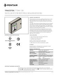
<strong>NGC</strong>-<strong>30</strong>Self-RegulatingCablesDistribution (for DigiTrace <strong>NGC</strong>-<strong>30</strong>-EMR only)Load powerStandard circuit breakersCircuit breaker amperage rating120 / 208 / 240 / 277 / 347 / 480 / 600 VacUS (United States country code in ordering details):Square D type QOB 120 / 208 / 240Square D type NF 277 / 480CA (Canada country code in ordering details):Cutler Hammer (Canada) type BAB 120 / 208 / 240Cutler Hammer (Canada) type GBH 277 / 480 / 347 / 600120 Vac208, 240, 277, 347, 480, 600 Vac20 A, <strong>30</strong> A, 40 A, 50 A20 A, <strong>30</strong> A, 40 A, 50 A, 60 APower-LimitingCablesMineral InsulatedCablesTypical DigiTrace <strong>NGC</strong>-<strong>30</strong> LayoutMultipoint temperature control withground-fault/current/temperaturemonitoring and optional distribution.LoadpowerterminalblockRTDterminalblocksContactorsThe DigiTrace <strong>NGC</strong>-<strong>30</strong> is a multipoint electronic control, monitoring, and powerdistribution system for heat-tracing used in process temperature maintenanceand freeze protection applications. The system contains DigiTrace controllers,multiple individual Electromechanical Relays (EMRs), or Solid-State Relays (SSRs)and an optional assembled circuit breaker panelboard with a main breaker.The DigiTrace <strong>NGC</strong>-<strong>30</strong> provides the following alarming features per control point.• High/low temperature• Ground fault• High/low current fault• RTD failureThe DigiTrace <strong>NGC</strong>-<strong>30</strong> provides ground-fault monitoring and trip protection forevery heat-tracing circuit and fulfills the requirements of national electricalcodes.<strong>NGC</strong>-UIT2-ORD or<strong>NGC</strong>-UIT2-HAZDistributionpanelboardMaincircuitbreaker<strong>NGC</strong>-<strong>30</strong>-CTM<strong>NGC</strong>-<strong>30</strong>-CR<strong>NGC</strong>-<strong>30</strong>-CRM/-CRMSSwing out panel (back view)LonglineHeatingRTB TubingBundlesTank Heating Snow and Ice Control andMonitoringHeat-TracePanelsLeft side panelRight side panelBack panelFront panelEMR PanelsNumber of control points Panelboard size EMR panel size with or without panelboard (nominal)5 12 space 42"H X 36"W x 12"D (wall mount)5 18 space 48"H X 36"W x 12"D (wall mount)10 18, 20, 24 space 48"H X 36"W x 16"D (wall mount)10 <strong>30</strong> space 72"H X 36"W x 16"D (includes 12" floor stands)15, 20, 25 <strong>30</strong> space 72"H X 36"W x 25"D (includes 12" floor stands)15, 20, 25 42 space 84"H X 36"W x 25"D (includes 12" floor stands)25, <strong>30</strong> 42 space 84"H X 36"W x 25"D (includes 6" floor stands)35, 40 42 space 90"H X 36"W x 25"D (includes 6" floor stands)EngineeredProductsSteam-TracingSystemsTechnical DataSheetsTHERMAL MANAGEMENT SOLUTIONS EN-DigiTrace<strong>NGC</strong><strong>30</strong>-DS-H58670 09/135 / 12Appendixes
<strong>NGC</strong>-<strong>30</strong>SSR PanelsNumber of control pointsSSR panel size without panelboard (nominal)5 36"H X <strong>30</strong>"W x 12"D (wall mount)10 48"H X 36"W x 16"D (wall mount)15, 20 72"H X 36"W x 24"D (includes 12" floor stands)25, <strong>30</strong> 84"H X 36"W x 24"D (includes 12" floor stands)35, 40 90"H X 36"W x 24"D (includes 6" floor stands)System ComponentsUser Interface Terminal (<strong>NGC</strong>-UIT2-ORD)The DigiTrace <strong>NGC</strong>-<strong>30</strong> User Interface Terminals (<strong>NGC</strong>-UIT2) are panel-mounteddisplays for use with the <strong>NGC</strong>-<strong>30</strong> panel. Available in different models, each <strong>NGC</strong>-UIT2-ORD has a 7 inch x 5 ¼ inch (17.5 cm X 13.3 cm) LCD color display withtouch-screen technology, and provides an easy user interface for programmingwithout using keyboards. It has RS-485, RS-232, or 10/100Base-T Ethernetcommunications ports that allow communication with the DigiTrace Supervisorsoftware and external Distributed Control Systems. A USB interface is includedfor easy configuration and firmware upgrades.The <strong>NGC</strong>-UIT2-ORD is designed for use in nonhazardous, indoor or outdoorlocation installations and is rated for NEMA 4 environments. The <strong>NGC</strong>-UIT2-ORDis installed locally on the panel door.User Interface Terminal (<strong>NGC</strong>-UIT2-HAZ)Same features as the <strong>NGC</strong>-UIT2-ORD except it has a 10.4 inch color display anddesigned for use in nonhazardous and hazardous locations (Class I, Division 2;Groups A, B, C, D).Card Rack Modules (<strong>NGC</strong>-<strong>30</strong>-CRM/-CRMS), Current Transformer Module (<strong>NGC</strong>-<strong>30</strong>-CTM) and Card Rack (<strong>NGC</strong>-<strong>30</strong>-CR)The Card Rack (<strong>NGC</strong>-<strong>30</strong>-CR) is mounted in a panel and it houses up to four CardRack modules (<strong>NGC</strong>-<strong>30</strong>-CRM/S). The Card Rack Modules (<strong>NGC</strong>-<strong>30</strong>-CRM/S) withthe associated Current Transformer Module (<strong>NGC</strong>-<strong>30</strong>-CTM) provide ground faultand line current information. The Card Rack modules also provide RTD input,alarming and switching of the Electrical Mechanical (<strong>NGC</strong>-<strong>30</strong>-CRM) and SolidState Relays (<strong>NGC</strong>-<strong>30</strong>-CRMS) for five heat tracing circuits.A typical panel consists of 8 Card Rack Modules wired together via a twisted pair(RS-485) cable for a total of 40 heating cable circuits. Additional panels can beconnected to a single User Interface Terminal to create a heat-tracing system ofup to 260 circuits.Voltage Monitoring Module (<strong>NGC</strong>-<strong>30</strong>-CVM) (optional)The Voltage Monitoring Module monitors the actual voltage being used by the<strong>NGC</strong>-<strong>30</strong>-CRM/-CRMS. The DigiTrace <strong>NGC</strong>-<strong>30</strong>-CVM module uses one channel onone CRM/-CRMS board in a panel.6 / 12EN-DigiTrace<strong>NGC</strong><strong>30</strong>-DS-H58670 09/13THERMAL MANAGEMENT SOLUTIONS
<strong>NGC</strong>-<strong>30</strong>Self-RegulatingCablesAdditional System Components (ordered separately)Remote User Interface Terminal (<strong>NGC</strong>-UIT2-ORD-R)Remote Monitoring Module (RMM2)DigiTraceDigiTrace Power Line Carrier Interface Module (PLI)H N CH N C B AThe Remote User Interface Terminal (<strong>NGC</strong>-UIT2-ORD-R) is a stand-alone displayfor use with the DigiTrace <strong>NGC</strong>-<strong>30</strong> panel. The <strong>NGC</strong>-UIT2-ORD-R is mountedremotely (in a nonhazardous location) when the DigiTrace <strong>NGC</strong>-<strong>30</strong> panel isplaced in a hazardous or difficult to access location. Like the <strong>NGC</strong>-UIT2-ORD, ithas a 7 inch x 5 ¼ inch (17.5 cm X 13.3 cm) LCD color display with touch-screentechnology, and provides an easy user interface for programming without usingkeyboards. It is rated NEMA 4 (IP 65), and must be mounted in a nonhazardousindoor or outdoor location.It has RS-485, RS-232, or 10/100Base-T Ethernet communications ports thatallow communication with the DigiTrace Supervisor software and externalDistributed Control Systems. A USB interface is included for easy configurationand firmware upgrades.A Remote Monitoring Module (RMM2) is used to collect temperatures for controland monitoring of the heat-tracing system by the DigiTrace <strong>NGC</strong>-<strong>30</strong> controlpanel. The RMM2 accepts up to eight RTDs that measure pipe, vessel, or ambienttemperatures. Multiple RMM2s communicate with a single <strong>NGC</strong>-UIT to providecentralized monitoring of temperatures. A single twisted-pair RS-485 cableconnects up to 16 RMM2s for a total monitoring capability of 128 temperatures.The RMM2s are placed near desired measurement locations in nonhazardous orhazardous locations.DigiTrace PLI modules (Power Line Carrier Interface) together with specialtemperature transmitters provide remote temperature-monitoring capability forheat-tracing control and monitoring systems by communicating the temperaturedata to the control system over the heat-tracing bus wires and the AC power line,eliminating the need for RTD wiring. Typical savings on the installation costs of aheat-tracing system can be as much as <strong>30</strong>% with PLI technology, depending onthe specifics of each application.The PLI module typically resides in the <strong>NGC</strong>-<strong>30</strong> EMR panel and receives inputfrom special transmitters connected to the heat-tracing. The transmittersprovide pipe temperatures from RTDs and continuity confirmation; they aretypically located at the front and/or end of the heat-tracing circuit. The PLI specialtransmitters are: DigiTrace SES (Smart End Seal), DigiTrace SPC (Smart PowerConnection) and DigiTrace 700-TT.The <strong>NGC</strong>-<strong>30</strong> system can accept up to 127 temperature inputs from SES/SPCtransmitters or 255 temperature inputs from 700-TT transmitters, per PLImodule. Up to four PLI modules can be connected to one <strong>NGC</strong>-<strong>30</strong> UIT.Power-LimitingCablesMineral InsulatedCablesLonglineHeatingRTB TubingBundlesTank Heating Snow and Ice Control andMonitoringHeat-TracePanelsEngineeredProductsSteam-TracingSystemsTechnical DataSheetsTHERMAL MANAGEMENT SOLUTIONS EN-DigiTrace<strong>NGC</strong><strong>30</strong>-DS-H58670 09/137 / 12Appendixes
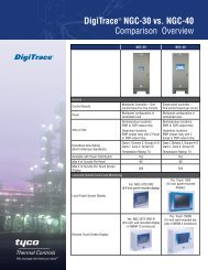
<strong>NGC</strong>-<strong>30</strong>Typical Configurations for the DigiTrace <strong>NGC</strong>-<strong>30</strong>Individual Controls with Ground-fault Trip/Current/Temperature Monitoring• Monitors ground-fault current andalarms/trip control contactor uponfault• Monitors heater current and alarmsupon low or high current conditions• Monitors pipe temperature (via RTDinputs wired back to the DigiTrace<strong>NGC</strong>-<strong>30</strong>) and alarms upon low orhigh currentcondition<strong>NGC</strong>-UIT2<strong>NGC</strong>-<strong>30</strong>-CRM/CRMS1 7 2 8 3 9 4 10 5 11 6 12C<strong>NGC</strong>-<strong>30</strong>-CTMPanelboardRTDPipeHeatingcableIndividual Controls with RMM2 for Ground-fault Trip/Current/Temperature Monitoring with Networked RTDs• Monitors ground-fault current andalarms/trip control contactor uponfault• Monitors heater current and alarmsupon low or high current conditions• Monitors pipe temperature (via RTDinputs wired back to the DigiTrace<strong>NGC</strong>-<strong>30</strong>) and alarms upon low orhigh current conditions• Using optional RMM2 (remotemonitoring modules) mounted in thefield, up to 128 RTD inputs can beadded to the <strong>NGC</strong>-<strong>30</strong> system.• The RMMs allow the RTD cables tobe terminated locally and only a singleRS-485 twisted wire pair broughtback to the panel. This results in asignificant reduction in field wiring.<strong>NGC</strong>-UIT2<strong>NGC</strong>-<strong>30</strong>-CRM/CRMS1 7 2 8 3 9 4 10 5 11 6 12CRTD<strong>NGC</strong>-<strong>30</strong>-CTMPanelboardIndividual Ambient or PASC Control with Ground-fault Trip/Current/Temperature Monitoring• Monitors ground-fault current andalarms/trip control contactor uponfault• Monitors heater current and alarmsupon low or high current conditions<strong>NGC</strong>-<strong>30</strong>-CRM/CRMSAmbientRTDRS-485PipeHeatingcablePipeHeatingcableRMM2Remotemonitoringmodule<strong>NGC</strong>-UIT21 7 C2 83 9 4 10 5 11 6 12<strong>NGC</strong>-<strong>30</strong>-CTMPanelboard8 / 12EN-DigiTrace<strong>NGC</strong><strong>30</strong>-DS-H58670 09/13THERMAL MANAGEMENT SOLUTIONS
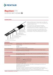
H N CH N C B AH N CH N C B AH N CH N C B A<strong>NGC</strong>-<strong>30</strong>Self-RegulatingCablesTypical Configurations for the DigiTrace <strong>NGC</strong>-<strong>30</strong>Multi-panel Configuration with RMM2 Module• Multiple panels can be gangedtogether for control using a singleUser Interface Terminal.• Communications is accomplishedusing RS-485 wiring.• Up to 260 heat trace circuits can besupported using this architecture.• DigiTrace Supervisor Softwareinterfaces with the User InterfaceTerminal via RS-485 or 10/100BaseTEthernet.Multi-panel Configuration with PLI and RMM2 Modules• Multiple panels can be gangedtogether for control using a singleUser Interface Terminal.• Communications is accomplishedusing RS-485 wiring.• Up to 260 heat trace circuits can besupported using this architecture.• Up to 1040 temperature inputs canbe monitored with one <strong>NGC</strong>-UIT2.• Up to 127 SES/SPC transmitters or255 700-TT transmitters per PLI andup to 4 PLI modules per <strong>NGC</strong>-<strong>30</strong>controllers for control ormonitoring.• 700-TT and SES/SPC Transmitterscan be used in any combination inthe same multi-panel configurationsystem using one <strong>NGC</strong>-UIT2.• The 700-TT and SES/SPC Transmitterscannot be used on the samePLI module. At least two PLI modulesare required if a combination of700-TT and SES/SPC transmittersare used.<strong>NGC</strong>-UIT2<strong>NGC</strong>-UIT2SES/SPCPanelPanelRS-485RS-485PanelPLI PLI PLIPanelPanelPanelRMM2RemotemonitoringmoduleRMM2RemotemonitoringmoduleReplacement ComponentsDescription Catalog number Part numberUser Interface TerminalUser Interface Terminal<strong>NGC</strong>-UIT2-ORD 10332-013Nonhazardous (Unclassified) Locations; indoors or outdoors,panel mountingUser Interface Terminal<strong>NGC</strong>-UIT2-HAZ 10332-022Nonhazardous (Unclassified) and Hazardous Locations; indoorsor outdoors, panel mountingUser Interface Terminal with NEMA 4 EnclosureNonhazardous (Unclassified) Locations; indoors or outdoor,remote stand-alone mounting<strong>NGC</strong>-UIT2-ORD-R 10332-016SES/SPCSES/SPCPower-LimitingCablesMineral InsulatedCablesLonglineHeatingRTB TubingBundlesTank Heating Snow and Ice Control andMonitoringHeat-TracePanelsEngineeredProductsSteam-TracingSystemsTechnical DataSheetsTHERMAL MANAGEMENT SOLUTIONS EN-DigiTrace<strong>NGC</strong><strong>30</strong>-DS-H58670 09/139 / 12Appendixes
<strong>NGC</strong>-<strong>30</strong>Replacement ComponentsDescription Catalog number Part number<strong>NGC</strong>-<strong>30</strong> ModulesCard Rack Module (for EMRs) <strong>NGC</strong>-<strong>30</strong>-CRM 10720-001Card Rack Module (for SSRs) <strong>NGC</strong>-<strong>30</strong>-CRMS 10720-004Current Transformer Module <strong>NGC</strong>-<strong>30</strong>-CTM 10720-002Voltage Monitoring Module <strong>NGC</strong>-<strong>30</strong>-CVM 10720-005<strong>NGC</strong>-<strong>30</strong> AuxiliaryDB9F-DB9F Null Modem Cable 5 ft <strong>NGC</strong>-UIT2-RS232 20577020Remote Monitoring Module RMM2 051778Remote Monitoring Module with NEMA 4X Enclosure RMM2-4X 523420Power Line Carrier Interface: Smart End Seal Transmitter120 V temperature/continuity transmitter with pipe-mount power connection SPC-P-1P000001049enclosure208–277 V temperature/continuity transmitter with pipe-mount powerSPC-P-2P000001050connection enclosure120 V temperature/continuity transmitter with wall-mount power connection SPC-W-1P000001051enclosure208–277 V temperature/continuity transmitter with wall-mount powerSPC-W-2P000001052connection enclosure120 V temperature/continuity transmitter SES-RTD-1 265212-000208–277 V temperature/continuity transmitter SES-RTD-2 677596-000120 V continuity transmitter SES-CONT-1 293536-000208–277 V continuity transmitter SES-CONT-2 398720-000120 V Smart End Seal replacement transmitter board SES-TT-1 815918-000208–277 V Smart End Seal replacement transmitter board SES-TT-2 771274-000Smart End Seal Replacement RTD and stand assembly SES-RTD-Replace 693618-000Power Line Carrier Interface: 700-TT TransmittersTemperature transmitter 700-TT-R 271095-000Transmitter enclosure- non-haz & Div. 2 locations inclusive of RTD-<strong>30</strong>0-10 700-TT-R-D2 427253-000RTD-Used with MONI-700-TT-R-D2 & MONI-700-TT-R-OPK RTD-<strong>30</strong>0-10 129977-000Transmitter enclosure- Div. 1 locations MONI-700-TT-R-D1 367651-000Transmitter enclosure for off-the-pipe non-haz & Div. 2 locations inclusive 700-TT-OPK 885215-000of RTD-<strong>30</strong>0-10Power Line Carrier Interface: Auxiliary EquipmentFront End Filter – 480 V MONI-700-FEF-480 V 922847-000Front End Filter – 600 V MONI-700-FEF-600 V P000000312PLI Module PLI 488323-000RTD lead wire, per 1000 ft reel MONI-RTD-WIRE 962661-000RS-485 comm. wire, per 1000 ft reel MONI-RS485-WIRE 549097-00010 / 12EN-DigiTrace<strong>NGC</strong><strong>30</strong>-DS-H58670 09/13THERMAL MANAGEMENT SOLUTIONS
<strong>NGC</strong>-<strong>30</strong>Self-RegulatingCablesOrdering Details<strong>NGC</strong>-<strong>30</strong> – Output – No. of Control Points – Enclosure – Voltage – Panelboard – Breaker or SSR or EMR – MCB – Options<strong>NGC</strong>-<strong>30</strong> – XXX – XX – XXX – XXX/XXX – XX – XX/XX (XX) – XXX – XOutputEMR = ElectromechanicalrelaySSR = Solid-staterelayNo. of control points5, 10, 15, 20, 25, <strong>30</strong>, 35, 40Enclosure12 = NEMA 12(indoors; painted steel)4 = NEMA 4/3R(outdoors; painted steel)4X = NEMA 4X/3RX(outdoors; stainless steel)Voltage120 / 208 Vac120 / 240 Vac 1277 / 480 Vac347 / 600 VacPanelboard0 = none requiredPanelboard size# of control 120/208 120/240 277/480 347/600points Vac Vac Vac Vac5 12 12 18 1810 24 20/<strong>30</strong> 18/<strong>30</strong> 18/2415, 20 <strong>30</strong>/42 <strong>30</strong>/42 <strong>30</strong>/42 <strong>30</strong>/4225, <strong>30</strong> <strong>30</strong>/42 <strong>30</strong>/42 <strong>30</strong>/42 <strong>30</strong>/4235, 40 42 42 42 421 Single phase2 Require remote <strong>NGC</strong>-UIT-ORD-123 Special - Describe special requirement in detail.4 Applies to Canada onlyOptionsCountry InstalledUS = U.S. and Americas (except Canada) [default]CA = CanadaE = Environmental purgeH = Electric heaterN = No UIT installed 2 (a remote <strong>NGC</strong>-UIT2-ORD-R can be ordered separately)PL = PLI Module with 3-pole standard breaker (EMR option panel only)U = If EMR, or SSR with panelboard, then <strong>NGC</strong>-UIT2-ORD installed (ordinary area)If SSR without panel, or Z purged, then <strong>NGC</strong>-UIT2-HAZ installed (hazardous area)V = Voltage monitoring (subtracts one control point)X = Spare partsZ = Z purge (EMR only; Class 1, Division 2 Hazardous Area)SP = Special 3Main circuit breaker0 = none required (choose if no panelboard required)Panelboardsize 120/208 Vac 120/240 Vac 277/480 Vac 347/600 Vac12 50, 100 50, 80, 100 – –18 – – <strong>30</strong>, 50 , 70, 125 20, 40, 60, 9020 – 50, 80, 100 – –24 50, 100 – – 20, 40, 60, 90<strong>30</strong> 50, 100, 150, 225 50, 80, 175, 225 50, 70, 125, 175, 225 40, 60, 90, 150, 20042 50, 100, 150, 225 50, 80, 175, 225 50, 70, 125, 175, 225 40, 60, 90, 150, 200Breaker or SSR or EMRBreakerNo. of C.B./No. of poles (ampere rating)No. of Panelboard 120 208 240 277 480 347 600control Vac Vac Vac Vac Vac Vac Vacpoints size (1P) (2P) (2P) (1P) (2P) (1P) (2P)5 12 5 5 55 18 5 4 5 4 5 4 5 5 5 510 18 – – – 10 6 10 610 20 10 – 9 – – – –10 24 10 10 – – – 10 1010 <strong>30</strong> – – 10 – – – –15 <strong>30</strong> 15 14 14 15 13 15 1315 42 – 15 15 – 15 – 1520 <strong>30</strong> 20 9 9 20 8 20 820 42 – 20 20 – 20 – 2025 <strong>30</strong> 25 4 4 25 4 25 425 42 25 16 16 25 15 25 15<strong>30</strong> <strong>30</strong> <strong>30</strong> – – <strong>30</strong> – <strong>30</strong> –<strong>30</strong> 42 – 10 10 – 10 – 1035 42 35 6 6 35 5 35 540 42 40 – – 40 – 40 –Note: The quantity of breakers must be equal to the number of control points.SSR without panelboardSelect no. of output devices (SSRs)/ no. of poles/amperageOutput devices: 5 – 40Poles:1P or 2PAmperage: <strong>30</strong>, 60EMR without panelboardSelect no. of output devices (EMRs)/ amperageOutput devices: 5 – 40Amperage: <strong>30</strong>, 60Power-LimitingCablesMineral InsulatedCablesLonglineHeatingRTB TubingBundlesTank Heating Snow and Ice Control andMonitoringHeat-TracePanelsEngineeredProductsSteam-TracingSystemsTechnical DataSheetsTHERMAL MANAGEMENT SOLUTIONS EN-DigiTrace<strong>NGC</strong><strong>30</strong>-DS-H58670 09/1311 / 12Appendixes
WWW.PENTAIRTHERMAL.COMNORTH AMERICATel: +1.800.545.6258Fax: +1.800.527.5703Tel: +1.650.216.1526Fax: +1.650.474.7711thermal.info@pentair.comEurope, Middle East, AfricaTel: +32.16.213.511Fax: +32.16.213.603thermal.info@pentair.comAsia PacificTel: +86.21.2412.1688Fax: +86.21.5426.2917cn.thermal.info@pentair.comLatin AmericaTel: +1.713.868.4800Fax: +1.713.868.2333thermal.info@pentair.com<strong>Pentair</strong>, DigiTrace, DigiTrace Supervisor, <strong>NGC</strong>, PLI, and RMM2 are owned by <strong>Pentair</strong> or its global affiliates. All other trademarks are the property oftheir respective owners. <strong>Pentair</strong> reserves the right to change specifications without prior notice.© 2010–2013 <strong>Pentair</strong>.THERMAL MANAGEMENT SOLUTIONS EN-DigiTrace<strong>NGC</strong><strong>30</strong>-DS-H58670 09/1312 / 12