Barolo ® Owner's Manual - Casablanca Fan
Barolo ® Owner's Manual - Casablanca Fan
Barolo ® Owner's Manual - Casablanca Fan

Create successful ePaper yourself
Turn your PDF publications into a flip-book with our unique Google optimized e-Paper software.
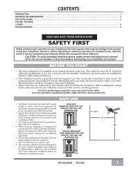
Ba r o l o ®Ba r o l o ® Owner’s <strong>Manual</strong>READ AND SAVE THESE INSTRUCTIONS!Safety and the proper operation of your <strong>Casablanca</strong> fan both require a thorough knowledge of the product and properinstallation; therefore, before attempting to install and operate your <strong>Casablanca</strong> fan, read this owner’s manual completely andcarefully. Retain this manual for future reference.Caution: To avoid possible electrical shock, make certain that electricity is turned off at the circuit breaker or fuse boxbefore attempting any installation procedure.CONTENTSIntroductionBefore You Start .................................................................................2Safe Use. .......................................................................................2MOUNTING RECOMMENDATIONSGeneral Guidelines ...............................................................................3Sloped Ceiling Installations ........................................................................3<strong>Fan</strong> InstallationGetting Started ..................................................................................4Crossbar Mounting Bracket Installation ...............................................................4Lag Screw Installation (Optional). ...................................................................5Canopy Installation ...............................................................................5<strong>Fan</strong> Preparation ..................................................................................6Hanging the <strong>Fan</strong> .................................................................................7Canopy Electrical Connections. .....................................................................7Canopy Hatch Installation .........................................................................7Blade Installation. ................................................................................8Inteli•TOUCH Control INSTALLATIONAdvan•TOUCH Control INSTALLATIONTroubleshooting tips .....................................................................15Care Recommendations ...................................................................16Product Specifications ...................................................................17PN C543010 AT01091
MOUNTING RECOMMENDATIONSGeneral GuidelinesBa r o l o ®Before mounting your <strong>Casablanca</strong> fan, read the following helpful recommendations. The location of the fan, air circulation,and fan size are all important factors to consider before installation.LocationCeiling fans have practical uses in almost every room in your home. We suggestyou follow these mounting recommendations as you decide where to installyour <strong>Casablanca</strong> fan.• For safety reasons, the fan blades must be a minimum of 7' above the floor.• Do not locate the fan in a doorway or above a swinging door.• In bedrooms, fans work best when mounted above the foot of the bed.• Over pool tables, be sure to provide plenty of clearance to avoid damage frompool cues.• In kitchens be sure to allow for open cupboard doors to clear the fanblades.• Do not install a fan close to or over a pool or spa. High humidity combined with corrosive gases will destroy the finish andwarp the blades.<strong>Fan</strong> Sizestandardmountingstylesupportbraceceiling outletboxSuggested Extension Pole LengthsCeiling HeightSloped Ceiling InstallationsPole Length8' 0" standard8' 6" standard9' 0" 6"9' 6" 12"10' 0" 12"11' 0" 18"12' 0" 24"13' 0" 36"14' 0" 48"ExtensionPoleMaximumHang-Tru ®angle 32º32°7' minimumBlades must be aminimum of 7 feetabove the floorWhen to Use Extension PolesFor optimum performance and appearance, an extensionpole should be used with your <strong>Casablanca</strong> fan wheninstalling on high (cathedral) ceilings or sloped ceilings.<strong>Casablanca</strong> offers standard poles in increments of 6" upto 5'. Custom poles are available in lengths up to 9'9". Seeyour Authorized <strong>Casablanca</strong> Dealer for details.Note: <strong>Fan</strong> may wobble or vibrate if pole length is not longenough and inside blade is too close to downslope or sidewall. Extending pole length will usually solve problem.Calculation of Ceiling AngleUse the tear-off Ceiling Angle Template card inserted in thismanual. It provides you with a simple “go” or “no-go” forinstalling your fan on a sloped ceiling.This slope is less than 32º.It is OK to install your fan.This slope is 32º. This is the maximumslope that will allow the fan to hangstraight down. It is OK to install your fan.This slope is more than 32º. Your fan will nothang straight down, an adaptor is necessary.Contact your local Authorized <strong>Casablanca</strong>Dealer in regards to purchasing a “SlopedCeiling Adaptor.”3
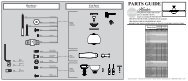
<strong>Fan</strong> InstallationGetting StartedInstalling a New Ceiling Fixture Outlet BoxIf you do not have an existing fixture located where you wishto place your <strong>Casablanca</strong> fan, an approved ceiling fixtureoutlet box must be installed and wired.warning!To reduce the risk of fire, electrical shock, orpersonal injury, mount to outlet box marked“Acceptable <strong>Fan</strong> Support of 22.7 kg (50 lbs.) orless” using the mounting hardware provided withthe outlet box.Using Existing Ceiling Fixture Outlet BoxAfter turning the power OFF at its source (either the circuitbreaker or fuse box), lower the old fixture and disconnectthe wiring. Check the ceiling fixture outlet box to be sureit is marked “Approved for Ceiling <strong>Fan</strong> Mounting.” If it isnot, a new box must be installed.Note: The weight of this fan is 37 pounds.Ceiling Hardware (not to scale)Crossbar Mounting Bracket InstallationCrossbar Mounting BracketScrew Pack A:Lag Screw and Washer (1)1" x 8-32 Roundhead Screw and Washer (2)Wire Nut (4)Note: After removing the old fixture, check the outlet boxto insure that it is supported by a joist or beam across itsupper surface. If not, a 2 x4 stud must be installed.JoistStep 1a. Remove the knockout plug in the center of theoutlet box or drill a 1 /2-inch hole for the lag screw to passthrough. Then drill a 1 /4-inch guide hole into the joist orbeam to a depth of 3 inches.Step 1b. Route the outlet box wires through the keyholeslot of the crossbar mounting bracket as shown. Attachthe crossbar mounting bracket to the outlet box with theprovided screws, making sure the outlet box wires are notpinched by the washer.CAUTION:To reduce the risk of personal injury, use only themounting hardware provided with the approvedoutlet box to install the crossbar mountingbracket.Ceiling-<strong>Fan</strong>-ApprovedWiring BoxCrossbar MountingBracketGreen Ground Wire1" x 8-32Roundhead ScrewCeiling WiringRidge side downWasherwarning!Support directly to building structure only.4
Ba r o l o ®NOTE: This step is required only under two conditions: Ifthe fan weighs 36 lbs. or more or if the existing ceiling fixtureoutlet box needs to be modified for a ceiling fan application(for example, if the house is not new construction and youare replacing an existing light fixture). We recommendthat the ceiling box be of sufficient capacity to support theweight of the fan and light fixture under any conditions. Ifin doubt whether you need to install the lag screw, consulta qualified electrician.Step 2. With the large washer attached, pass the lag screw(Pack A) through the center hole of the crossbar mountingbracket and screw into the guidehole. Tighten until theoutlet box is mounted firmly to the beam. This box mustbe secured to the ceiling firmly.Lag Screw InstallationCanopy Hardware (not to scale)Canopy InstallationCanopy HatchCanopyScrew Pack B:Canopy Screws andLock Washers (5)Step 3. Attach the canopy to the crossbar mounting bracketwith three of the 8-32 x 2 1 /2" long canopy screws (ScrewPack B) and lock washers provided with your <strong>Casablanca</strong>fan. Tighten using the provided screwdriver until snugagainst the ceiling.NOTE: On sloped ceilings, align the canopy opening withthe top or peak of the room.Feed outlet boxwires throughcanopy openingCanopyLock WasherCanopy Screw5
Ba r o l o ®Step 5a. To hang the fan body in the canopy, hold the fanbody firmly and insert the ball into the canopy opening.Check that no wires are pinched. Rotate the fan body untilthe slot in the ball fits into the pin opposite the canopyopening.Step 5b. Trim excess motor wires, leaving at least 6 inchesabove the downrod. Strip 1 /2-inch insulation from the endof each wire using a wire stripper (available at your localhardware store). The splices after being made should beturned upward and pushed carefully into the outlet box.Hanging the <strong>Fan</strong>BallSlotPinCanopy Electrical ConnectionsStep 6. Attach the fan wires to the ceiling fixture outlet boxwiring by placing the bare ends of the wires side by side andthen securing with a wire nut. Test that the connection issecure by pulling on the wire nut. Connect in this order:• GREEN leads from mounting plate and downrodassembly of fan to GROUND conductor of powersource. Secure with wire nut.• WHITE wire from fan to white NEUTRAL wire inceiling fixture outlet box. Secure with wire nut.• BLACK power wire from fan to black power wirein ceiling outlet box. Secure with wire nut.After making the wire connections, the wires shouldbe spread apart with the grounded conductor and theequipment-grounding conductor on one side of the outletbox and the ungrounded conductor on the other side ofthe outlet box.NOTE: If the color of your ceiling wires differs from thatdescribed, consult an electrician.2 BLACK wires2 WHITE wires3 GREEN wiresWire nutStep 7a. Tuck the wires into the canopy with the wire nutspointed upwards, so that the WHITE and BLACK wiresare on opposite sides of the canopy and all wires are clearof the canopy opening.Step 7b. Install the canopy hatch with the last canopy screwand lock washer using the provided screwdriver. To do this,tilt the fan body away from the hatch opening. Tightenthe screws firmly.Step 7c. Straighten the fan, then check to ensure there isno movement between the canopy and the ceiling or thePerma•Lock downrod and the ball assembly.Canopy Hatch Installation7
RLight-Minder ProgramThe Light-Minder program automatically turns OFF the fan mounted lights aftertwo hours.To enter the Light-Minder Program:1. Turn the POWER OFF for at least three seconds.2. Turn the POWER ON3. Immediately operate the buttons in the following sequence:FAN + FAN + LIGHT + LIGHT4. A series of tones indicates this command has been accepted.The fan and light will operate normally using the buttons to turn them on and off.But, if the lights are left on, they will automatically shut off after two hours. To cancelthe Light-Minder Program, turn the POWER off for three seconds.The Safe-Exit Program gives you about thirty seconds of light whenyou turn the lights off, enabling you to exit your home before thelights go out.To enter the Safe-Exit Program:1. Turn the POWER off for at least three seconds.2. Turn the POWER on.3. Immediately operate the buttons in the following sequence:FAN + FAN + LIGHT + LIGHTAfter you hear the confirming audio tones from the fan- immediately press LIGHT4. The lights will blink to indicate this command has beenaccepted.The lights will stay on for twenty seconds and then begin to dim.After a total of thirty seconds has elapsed, the lights will be offcompletely. To cancel the Safe-Exit Program, turn the POWERoff for three seconds.Safe-Exit ® ProgramHome-Safe ® ProgramThe Home-Safe Program makes an unoccupied home appear occupied by turning the lightson and off at random times.To enter the Home-Safe Program:1. Turn the POWER off for at least three seconds.2. Turn the POWER on.3. Immediately operate the buttons in the following sequence:4. A tone and flashing light indicate this command has been accepted.This program overrides all manual control of lights and fan. The lights will now beautomatically cycled on and off in a controlled sequence as follows: On 1 hour, off 1 /2 hour,on 2 hours, off 1 hour, on 1 /2 hour then off 2 hours.This seven hour pattern will repeat continuously so that a different pattern of lighting isseen each day of the week.To cancel the Home-Safe Program, turn the POWER off for three seconds.<strong>Fan</strong>-Minder ProgramNote: Both Light-Minder and Safe-Exit programs can run at thesame time, however the dimmer cannot be used, the light may onlybe turned ON/OFF.The <strong>Fan</strong>-Minder feature will add to your comfort when used in the bedroom. The program reduces the speed ofthe fan each two-hour interval to compensate for the cooling night air.To enter the <strong>Fan</strong>-Minder Program:1. Turn the POWER off for at least three seconds.2. Turn the POWER on.3. Immediately operate the buttons in the following sequence:LIGHT + LIGHT + FAN + FAN4. The fan controller will respond with three descending tones. A timer is now initiated and the fan will reduceone speed for each two-hour interval. The fan will not, however, descend below the second lowest speed.To cancel the <strong>Fan</strong>-Minder Program, turn the POWER off for three seconds. You may increase the fan speed bypressing and holding the button until the desired speed is reached, then release it. The fan will again reduce onespeed for each 2 hour interval.In t e l i•To u c h ®11
Ad v a n•To u c h ®Step 1. Remove the two 6-32 x5/16” screws holding the bracket tothe holster. Save screws for later.Advan•TOUCH Control INSTALLATIONW-62 Bracket / Holster RemovalHolsterControl Bracket InstallationBracketSAFETY FIRST: To reduce the risk of electrical shock, this fan must be installed with an isolating wall control/switch.CAUTION! Do not use with wall dimmer.WARNING: To reduce the risk of fire or electric shock, do not use this fan with any solid state speed control device. Useonly the control provided with this fan.StandardToggleSwitchRockerLightSwitchInnermountingholesOutermountingholesStandard Light SwitchStep A. Remove the two screws holding the switch coverplate. Do not remove the cover plate.Step B. Orient the control bracket as shown and line up thetwo inner mounting holes with those on the switch.Step C. Insert and tighten the screws using the providedscrewdriver.Wall Installation12ControlBracketStep A. Locate a 2x4wall stud in a convenientlocation.Step B. Orient the controlbracket as shown over the2x4 stud.Step C. Insert the 1" woodscrews in either the inner orouter mounting holes andtighten using the providedscrewdriver.Step 2SwitchCoverPlateRocker Light SwitchControlBracketSwitchCoverPlateStep A. Break off the two tabs by pushing outward.Step B. Remove the two screws holding the switch coverplate. Do not remove the cover plate.Step C. Orient the control bracket as shown and line upthe two inner mounting holes with those on the switch.Step D. Insert and tighten the screws using the providedscrewdriver.NOTE: The wall anchors and 6-32 x 1" screws may beused in situations where mounting to a stud is not possible.Use the inner mounting holes. After securing the anchor,discard the anchor’s pointed screws and use the 6-32 decorovalhead screws supplied.WoodScrew 1"AnchorPanheadScrewAttach Holster to BracketDrywall AnchorDecor Ovalhead Screw6-32 X 1"After you have completed installing the bracket to the wall, using the 2 screws removed in Step 1, attach the W-62 holsterto the bracket.
Battery InstallationAd v a n•To u c h ®Ba r o l o Open Battery Door bypressing down on theinsert tab provided.BatteryDoorInstall 4 “AAA” alkalinebatteries in the space provided.Please observe proper polarityplacement. Replace BatteryDoor.Important Operating NotesPower turned off, interrupted or failure:The remote control is battery operated, therefore if the power is turned off, interrupted or you experience a power failure, theremote control remembers the previous setting for both fan and light.Button operation:Rapid button operation causes erratic fan operation.For reliable operation of the remote control and fan you must wait one second between button presses to allow the radiosignal to be transmitted to the fan and received.Operation<strong>Fan</strong> OperationThe Advan•Touch fan is controlled by the remote control. The fan button locatedin the center top row turns the fan on or off.With the fan on, the control display will show an up or down moving arrow thatindicates direction and places a box around the operating speed. It will also showyou a moving fan image that tells you the fan is on and what direction the bladesare moving in (looking up from underneath the fan).Just below the fan button, there are two and buttons. Use the button(on the left) to increase fan speed once for each press and the button (on theright) to decrease speed once for each press.Use the reverse button to change the direction of the rotation. Reverse operates atany speed. The fan returns to its set speed after reversing.You will see the airflow direction arrow change each time to press reverse.Light OperationThe light is turned on or off independently of the fan by pressing the LIGHT button.Keep pressing the button (hold it down) and it becomes a dimmer. The light variesfrom “bright” to “dim” over approximately 8 seconds. This sequence will reverse thelight when it reaches the brightest or dimmest level if you continue to hold theLIGHT button. Release the button when the desired level is reached.Safe Exit FeatureTo turn off the light, press the button once and the light will increase slightly if lessthan 100% and gradually turn off, taking approximately 20 seconds. (If set at 100%,light will decrease to about 50% and then gradually turn off.) This enables you toleave a room or your home safely before the lights go completely out.Press the light button two times and the light will immediately dim to about halfand then turn off completely.The fan will remember the last light setting and will come on at that setting untilcharged.Bulb Saver FeatureWhen the light is turned on, the brightness will take 1.5 seconds until it reachesthe present level. This feature helps extend light bulb life.13
PROBLEM<strong>Fan</strong> will not startBa r o l o ®Troubleshooting tipsPlease refer to this troubleshooting guide before requesting service or contacting your dealer for assistance.<strong>Fan</strong> wobbles or shakes excessively<strong>Fan</strong> is noisy during operation<strong>Fan</strong> does not run on low speedBattery life is shortPOSSIBLE REMEDIES• Check the main circuit fuses, circuit breakers, and wall switch position. Check all wireconnections. Make sure the power is turned off during this inspection.• The battery is weak. Install a fresh battery.• The fan receiver is defective. Replace the fan receiver.• Check the frequency setting: Turn the power off at the circuit breaker for the fan that isnot functioning only. Check that the jumper switches match in both the receiver and thetransmitter.• Be sure the canopy pin is set properly into the slot on the ball.• Check that the bladeholders have not been bent during installation and the blades arebalanced.• The hanger bracket and/or the ceiling outlet are attached too loosely. Make sure the hangerbracket is attached tightly to the ceiling outlet box and the downrod assembly is securedfirmly.• The downrod is attached to the downrod base too loosely. Make sure all the screws aresecurely tightened.• Check and tighten the light fixture retaining screws, glass shade screws, and/orlightbulb(s).• Tighten the canopy screws and mounting plate assembly. Make sure the wire nuts inside thecanopy and switch housing are not touching the metal parts and that they have not fallenoff the wire splices. Tighten as necessary.• Tighten the blade holders to the flywheel (or direct drive motor) and the blades to thebladeholder screws.• Make sure all the screws in the motor housing are snug but not overly tight.• If fan is new, it may need to be “broken in.” Run at high speed for several days.• Replace with alkaline batteries.Lights flash or blink, fan may rotate or make audible tones during operation ofW-23 wall controls. • Normal Operation.When AC power is turned on for the first time, the lights operate normally,but W-32 wall control operation is reversed. <strong>Fan</strong> button operates lights,Light button operates the fan.<strong>Fan</strong> or lights appear to operate by themselves (changing speed or intensity),Light button operates the fan. Wall control operation is intermittent.<strong>Fan</strong> OK, no lightLight OK, no fanRemote control of fan is erratic<strong>Fan</strong> starts working by itselfInteli•TOUCH ®Advan•TOUCH®• Check for burned out light bulb. Check fan light wires.• Check connectors, may not be making good contact.• Reverse the 2 black and whitestriped wire connections.• Check AC supply for irregularities,(noise spikes, fluctuations, or failure);or circuit board assembly.• Check batteries installed correctly. Install fresh ALKALINE batteries.• Frequency interference; Change dip switch code.This device complies with RSS-210 of Industry Canada. Operation is subject to the following two conditions: (1) this device may not cause interference, and (2) this device must accept any interference, includinginterference that may cause undesired operation of the device.1. This device complies with part 15 of the FCC Rules. Operation is subject to the following two conditions: (1) this device may not cause harmful interference, and (2) this device must accept any interferencereceived, including interference that may cause undesired operation.2. This equipment has been tested and found to comply with the limits for a Class B digital device, pursuant to Part 15 of the FCC Rules. These limits are designed to provide reasonable protection againstharmful interference in a residential installation. This equipment generates, uses and can radiate radio frequency energy and, if not installed and used in accordance with the instructions, may cause harmful interferenceto radio communications. However there is no guarantee that interference will not occur in a particular installation. If this equipment does cause harmful interference to radio or television reception,which can be determined by turning the equipment off and on, the user is encouraged to try to correct the interference by one or more of the following measures: Reorient or relocate the receiving antenna,Increase the separation between the equipment and receiver, Connect the equipment into an outlet on a circuit different from that to which the receiver is connected. Consult the dealer or an experiencedradio/TV technician for help. Note: Any changes or modifications to the transmitter or receiver not expressly approved by <strong>Casablanca</strong> <strong>Fan</strong> Company may void one’s authority to operate this remote control.15
<strong>Fan</strong> Finishes• For cleaning, a soft brush or lint-free cloth should be used to prevent scratching the finish.• A vacuum cleaner brush nozzle can remove heavier dust.Care Recommendations• Surface smudges or an accumulation of dirt and dust can be removed easily using a mild detergent and slightly dampenedsoft cloth. An antistatic agent may be used, but never use abrasive cleaning agents as these will damage the finish.Blades• Wood-finish blades should be cleaned with a furniture polishing cloth. Occasionally, a light coat of furniture polish may beapplied for added protection and beauty.• For painted and high-gloss blades, surface smudges or an accumulation of dirt and dust can be removed easily using a milddetergent and slightly dampened soft cloth. An antistatic agent may be used, but never use abrasive cleaning agents as thesewill damage the finish.No Need for Lubrication• Never lubricate this fan! The precision motor at the heart of your <strong>Casablanca</strong> fan features sealed bearings that are lubricatedfor life.• Do not attempt to oil the motor.Changing Lightbulbs• Be sure to turn the power to OFF at the wall switch or circuit breaker before changing lightbulbs.• Replace bulbs with the same type as you removed from the light fixture.• The maximum wattage rating for this fan’s light kit is 360 watts for the downlight.For questions or to locate the nearest <strong>Casablanca</strong> Authorized Service Center call toll free: 1-888-227-2178or visit us on the web at: www.casablancafanco.comThis device complies with Part 15 of the FCC rules. Operation is subject to the following two conditions:1. This device may not cause harmful interference.2. This device must accept any interference received, including interference that may cause undesired operation.This equipment has been tested and found to comply with the limits for a class B digital device, pursuant to Part 15 of theFCC rules. These limits are designed to provide reasonable protection against harmful interference in a residential installation.This equipment generates, uses, and can radiate radio frequency energy and, if not installed and used in accordance with theinstructions, may cause harmful interference to radio communication. However, there is no guarantee that the interferencewill not occur in a particular installation. If this equipment does cause harmful interference to radio or television reception,which can be determined by turning the equipment off and on, the user is encouraged to try to correct the interference byone or more of the following measures:• Reorient or relocate the receiving antenna.• Increase the separation between the equipment and receiver.• Connect the equipment into an outlet on a circuit different from that to which the receiver is connected.• Consult the dealer or an experienced radio/TV technician for help.NOTE: Any changes or modifications to the transmitter or receiver not expressly approved by <strong>Casablanca</strong> <strong>Fan</strong> Companymay void one's authority to operate this remote control.16
Ba r o l o ®Product SpecificationsModel Name:Model Number:<strong>Barolo</strong>®C5SXX A/TDimensions: A = 11"B = 13"NOTE: Dimension Bincludes light fixtureand glass.Weight:C = 3"d = 13"E = 5.6"37 lbs.Motor:XLP2000Blade Span: 44" & 52"Blade Iron Pitch: 14°No. of Blades: 5Technology: Inteli•Touch W-32Advan•Touch W-62Airflow:Electricity Use*:Airflow Efficiency*:6,059 cfm104 watts58.2 cfm/watt* Performance data is for fan only. No lighting wattage is included.Measurements taken with 21" basic blades.17