

The 1.4-ltr. 16V 55kW Engine - Volkswagen Technical Site
The 1.4-ltr. 16V 55kW Engine - Volkswagen Technical Site
The 1.4-ltr. 16V 55kW Engine - Volkswagen Technical Site

Create successful ePaper yourself
Turn your PDF publications into a flip-book with our unique Google optimized e-Paper software.
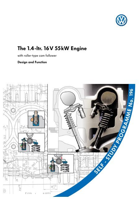
<strong>The</strong> <strong>1.4</strong>-<strong>ltr</strong>. <strong>16V</strong> <strong>55kW</strong> <strong>Engine</strong>with roller-type cam followerDesign and Function196SELF- STUDY PROGRAMME No.
Whether it’s a matter of better fuel economy, higher engine output or lower exhaust emissions - thedemands on engines are constantly increasing.This presents our engineers with new tasks, with the result that the <strong>Volkswagen</strong> engine range is constantlygrowing.Example: weight savingDuring development, the weight of the new <strong>1.4</strong>-<strong>ltr</strong>. <strong>16V</strong> <strong>55kW</strong> engine was reduced by about 10 kg bymodifying its design.196_168This self-study programme explains the technicalinnovations in our engine range using the <strong>1.4</strong>-<strong>ltr</strong>.<strong>16V</strong> <strong>55kW</strong> engine as an example.<strong>The</strong>se differences arise out of the various technicaldemands on the engines and are describedin this Self-Study Programme.Apart from minor differences in the enginemechanics, the 1.6-lr. <strong>16V</strong> 88kW engine for thePolo GTI will have these new features, too.NewImportant2<strong>The</strong> Self-Study Programmeis not a Workshop Manual.Precise instructions for testing, adjustment andrepair can be found in the appropriate WorkshopManual.
At a glanceIntroduction . . . . . . . . . . . . . . . . . . . . . . . . . . . . . . . . . 4Specifications . . . . . . . . . . . . . . . . . . . . . . . . . . . . . . . . . . . . . . . . . . 5<strong>Engine</strong> mechanics . . . . . . . . . . . . . . . . . . . . . . . . . . . . . 6Intake manifold . . . . . . . . . . . . . . . . . . . . . . . . . . . . . . . . . . . . . . . . 6Valve gear . . . . . . . . . . . . . . . . . . . . . . . . . . . . . . . . . . . . . . . . . . . . 7Valve actuation . . . . . . . . . . . . . . . . . . . . . . . . . . . . . . . . . . . . . . . . 8toothed belt drive . . . . . . . . . . . . . . . . . . . . . . . . . . . . . . . . . . . . . . 11Crankcase . . . . . . . . . . . . . . . . . . . . . . . . . . . . . . . . . . . . . . . . . . . 12Crankshaft . . . . . . . . . . . . . . . . . . . . . . . . . . . . . . . . . . . . . . . . . . . 13Sealing flange . . . . . . . . . . . . . . . . . . . . . . . . . . . . . . . . . . . . . . . . 14Oil pump . . . . . . . . . . . . . . . . . . . . . . . . . . . . . . . . . . . . . . . . . . . . 16Con rod . . . . . . . . . . . . . . . . . . . . . . . . . . . . . . . . . . . . . . . . . . . . . 18Exhaust system . . . . . . . . . . . . . . . . . . . . . . . . . . . . . . . . . . . . . . . .19<strong>Engine</strong> management . . . . . . . . . . . . . . . . . . . . . . . . . . 21<strong>Engine</strong> control unit . . . . . . . . . . . . . . . . . . . . . . . . . . . . . . . . . . . . .21System overview . . . . . . . . . . . . . . . . . . . . . . . . . . . . . . . . . . . . . . 22Static high-voltage distribution . . . . . . . . . . . . . . . . . . . . . . . . . . 24<strong>Engine</strong> speed sender G28 . . . . . . . . . . . . . . . . . . . . . . . . . . . . . . 25Hall sender G40 . . . . . . . . . . . . . . . . . . . . . . . . . . . . . . . . . . . . . . 26Functional diagram . . . . . . . . . . . . . . . . . . . . . . . . . . . . . . . . . . . 28Self-diagnosis. . . . . . . . . . . . . . . . . . . . . . . . . . . . . . . . . . . . . . . . . 30Service . . . . . . . . . . . . . . . . . . . . . . . . . . . . . . . . . . . . .32Special-purpose tools . . . . . . . . . . . . . . . . . . . . . . . . . . . . . . . . . . 323
IntroductionOne of a “new generation”<strong>The</strong> <strong>1.4</strong>-<strong>ltr</strong>. <strong>16V</strong> <strong>55kW</strong> engine is the first of a newgeneration of engines featuring roller-type camfollowers.It is fundamentally different fromthe <strong>1.4</strong>-<strong>ltr</strong>. <strong>16V</strong> 74kW engine with bucket tappets.<strong>The</strong> main differences are:- the die cast aluminium crankcase- the cylinder head, where only the existingvalve clearance and angle have beenadopted.New and advanced developments include:the plastic intake manifold196_068the cylinder head andcamshaft housingvalves are activated byroller-type cam followersthe crankcase is made ofdie cast aluminiumthe duocentric oil pump<strong>The</strong> overall effects of these design modificationsare:- significant reduction in fuel consumption,- performance on a par withpredecessor models,- weight savings and- compliance with the more stringentexhaust gaslimit values now in effect in Germany.the exhaust manifoldthe Magneti Marelli 4AVengine managementsystem4
Specifications<strong>1.4</strong>-<strong>ltr</strong>. <strong>16V</strong> <strong>55kW</strong> engineTorque[Nm]Output[kW]<strong>The</strong> <strong>1.4</strong>-<strong>ltr</strong>. engine develops 128Nm of torque at3200rpm. Maximum output is <strong>55kW</strong> at5000rpm.196_070<strong>Engine</strong> speed [rpm]1.6-<strong>ltr</strong>. <strong>16V</strong> 88kW engineTorque[Nm]Output[kW]By comparison, the 1.6-<strong>ltr</strong>. engine develops148Nm of torque at 3400rpm and a maximumoutput of 88kW at 6200rpm.196_088<strong>Engine</strong> speed [rpm]<strong>Engine</strong> code<strong>1.4</strong>-<strong>ltr</strong>. engineAHWAKQ exhaust emission level D31.6-<strong>ltr</strong>. engineAJV exhasut emission level D3Displacement [cm 3 ] 1390 1598Bore/stroke [mm] 76.5 / 75.6 76.5 / 86.9Compression ratio 10.5:1 10.6:1Mixture preparation<strong>Engine</strong> management systemMagneti Marelli 4AVMagneti Marelli 4AVFuel [RON] 95 / 91 98 / 95Exhaust gas post-treatmentLambda control,main catalytic converter forMVEG-A II for the AHW engineadditional micro catalytic converterfor exhaust emission levelD3 for the AKQ engineLambda control,primary andmain catalytic convertersfor exhaust emission level D3<strong>The</strong> knock control lets you run the <strong>1.4</strong>- <strong>ltr</strong>. and 1.6-<strong>ltr</strong>. engines on RON 91 and RON 95 fuel respectively.This may result in a slight loss of power and torque.5
<strong>Engine</strong> Mechanics<strong>The</strong> plastic intake manifoldconsists of three component parts which are weldedtogether. <strong>The</strong> material is made of highgradepolyamide which is resistant to temperaturesof up to 140°C for short periods of time.<strong>The</strong> use of plastics has made it possible to keepthe weight of the intake manifold down to threekilograms. As a result, the intake manifold is roughly36% lighter than a comparable intake manifoldmade of aluminium.<strong>The</strong> plastic intake manifold also has a verysmooth surface, and this improves the inducedair flow.<strong>The</strong> following components are mounted in theplastic intake manifold:- the injectors,- the fuel distributor,- the throttle valve control unit and- the intake manifold pressure sender and theintake air temperature sender.<strong>The</strong> air filter housing is secured to the plasticintake manifold by two screws.<strong>The</strong> max. permissible tightening torque is3.5Nm.induced airUpper shellMiddle sectionUpper/lower parts ofintake manifold<strong>The</strong> plastic intake manifoldof the <strong>1.4</strong>-<strong>ltr</strong>. engine196_071An aluminium intake manifold is used for the 1.6-<strong>ltr</strong>. <strong>16V</strong> 88kW engine.It has been adapted to the engine’s requirements.6
Valve gearis accommodated in the cylinder head andcamshaft housing.<strong>The</strong> camshaft housing is by and largeidentical to the cylinder head coverwhich was previously used as standard.What’s new is that the camshafts arenow inserted into the housing. <strong>The</strong> bearingcovers and camshaft housing limit the axial clearanceof the camshafts.<strong>The</strong> camshafts run in three bearings.<strong>The</strong> valve assembly comprising valves, rollertypecam followers and hydraulic support elementsis located in the cylinder head.ExhaustcamshaftCamshaft housingHydraulic support elementIntakecamshaft196_018Cylinder headRoller-type cam followerBearing coverInserted camshaftCamshaft housing196_075Cylinder head<strong>The</strong> gasket between the camshaft housing and the cylinder head is in the form of a fluid seal.Do not apply the sealant too thickly, since this may cause excess sealant to enter the oil drillingsand damage the engine.7
<strong>Engine</strong> MechanicsValve activationWith this engine generation, the valves are activatedvia a roller-type cam follower with ahydraulicsupport element.Advantages:- less friction- fewer moving masses.Conclusion:Less engine power is required to drive the camshafts.CamshaftCam rollRoller-typecam followerHydraulicsupport elementValveLow-frictionroller bearing196_010Design<strong>The</strong> roller-type cam follower comprises a sheetmetalmoulding acting as a lever and a cam rollwith a roller bearing.<strong>The</strong> cam follower is clipped onto the support elementand seated on the valve.<strong>The</strong> hydraulic support element has the samefunction as the hydraulic bucket tappet. It servesas a hydraulic valve lifter and support for theroller-type cam follower.8
<strong>The</strong> lubrication systemLubricant flows between the hydraulic supportelement and the roller-type cam follower as wellas between the cams and the cam roll along anoil duct integrated in the support element.Oil is injected into the cam roll through a drillingin the roller-type cam follower.OilCam rollLubricant duct196_009Function<strong>The</strong> support element serves as a pivot for the roller-typecam follower. <strong>The</strong> cam contacts the camroll and presses the lever down. <strong>The</strong> lever in turnactivates the valve.A high valve lift is achieved with a relativelysmall cam due to the fact that the leverage betweenthe cam roll and support element is smallerthan between the valve and support element.It is not possible to inspect the hydraulic support elements.196_0119
<strong>Engine</strong> Mechanics<strong>The</strong> hydraulic support elementserves as a support for the roller-type camfollower and hydraulic valve lifter.Design<strong>The</strong> support element is connected to the oilcircuit. It comprises the following elements:- a piston,- a cylinder and- a piston spring.A small ball, in combination with a pressurespring integrated in the lower oil chamber,makes up the one-way valve.Hydraulic valve lifterOil inletPiston springOne-way valvePiston withdrillingCylinderUpperoil chamberLoweroil chamber196_014If valve backlash occurs, the piston spring forcesthe piston out of the cylinder until the cam rollmakes contact with the cam. When the piston ispressed out of the cylinder, the oil pressure in thelower oil chamber drops.<strong>The</strong> one-way-valve opens and surplus oil flowsinto the oil chamber.<strong>The</strong> one-way-valve closes when the pressurebetween the lower and upper oil chambers hasbeen equalised.Valve clearance196_0<strong>16V</strong>alve liftWhen the cam contacts the cam roll, the pressureinside the lower oil chamber rises becausethe oil here cannot be compressed. <strong>The</strong> pistoncannot be forced any further into the cylinder.Thus, the support element acts as a rigid supportfor the roller-type cam follower.<strong>The</strong> inlet or exhaust valve opens.196_01710
<strong>The</strong> toothed belt driveConnecting drive<strong>The</strong> toothed belt drive is divided into a maindrive and a connecting drive on account of thesmall overall width of the of the cylinder head.Main driveMain drive<strong>The</strong> coolant pump and the intake camshaft aredriven by the crankshaft by means of a toothedbelt integrated in the main drive. An automatictension pulley and two deflection pulleys reducetoothed belt fluctuation.DeflectionpulleyBelt pulleyCoolant pumpTension pulleyMain driveTension pulleyConnecting driveDeflectionpulley196_021Belt-drivencrankshaft gear<strong>The</strong> connecting driveis located outside the cylinder head.<strong>The</strong> exhaust camshaft is driven by theintake camshaft by means of a second toothedbelt integrated in the connecting drive.Again, an automatic tension pulley reduces toothedbelt fluctuation.196_024You can find exact instructions for adjustment the camshaft timing in the Workshop Manual.11
<strong>Engine</strong> Mechanics<strong>The</strong> crankcaseused in the <strong>1.4</strong>-<strong>ltr</strong>. <strong>16V</strong> <strong>55kW</strong> engine is made ofdie cast aluminium.<strong>The</strong> liners are made of gray cast iron. <strong>The</strong>y arepress-fitted in the crankcase and machinable.Land withpress-fitted cast ironlinersCoolant ductSection of thealuminium crankcase ofthe <strong>1.4</strong>-<strong>ltr</strong>. engine196_086For corrosion reasons, only coolant additive G12 is approved for use.12
<strong>The</strong> crankshaftis manufactured from gray cast iron and has onlyfour balancing weights. Despite this weightsaving, the crankshaft has the same running characteristicsas a crankshaft with eight balancingweights.<strong>The</strong> 1.6-<strong>ltr</strong>. <strong>16V</strong> 88kW engine has a crankshaftwith eight balancing weights.Bearing seatsBalancing weight196_087CrankshaftBalancing weightBalancing weightBearing coverYou must not remove or loosen the crankshaft in the <strong>1.4</strong>-<strong>ltr</strong>. engine.Even when you loosen the bearing cover screws, the inner structure of thealuminium bearing seat relaxes, resulting in deformation of the crankshaft.If you undo the bearing cover screws, you must replace the crankcase complete withthe crankshaft.13
<strong>Engine</strong> Mechanics<strong>The</strong> sealing flange<strong>The</strong> crankcase is sealed with a sealing flange on the clutch side.<strong>The</strong> sender wheel for the engine speed sender G28 is integrated in the sealing flange.In future, sealing flanges of two manufacturers will be used for this engine generation.<strong>The</strong> designs of these sealing flanges (e.g. engine speed sender housing) differ to such an extentthat they cannot be replaced with another make of sealing flange.Sealing flange with spring-ring gasket<strong>Engine</strong> speed sender G28In this case, the joint between the sealing flangeand the sender wheel is sealed with a spring-ringgasket. <strong>The</strong> sender wheel is also sealed off fromthe crankshaft by an elastomer gasket. <strong>The</strong> senderwheel is precisely pressed onto the crankshaft.CrankshaftElastomer gasketSender wheelGasketSealing takes place atthe sender wheel.Section ofcrankshaft196_099Sealing flangeSender wheelsender wheelSealing flange196_10014
Sealing flange with PTFE sealing ringPTFE stands for polytetrafluorethylene.It is better known as Teflon - a special type ofheat- and wear-resistant plastic.<strong>The</strong> PTFE sealing ring sealing is located directlybetween the sealing flange and crankshaft.No additional elastomer gasket is needed. Withthis type of sealing flange, too, the sender wheelis pressed onto the crankshaft in a precise position.<strong>Engine</strong> speed sender G28PTFE gasketCrankshaftPTFE sealing ringSealing takes place onthe crankshaft.196_097Sealing flangeSender wheelSection ofcrankshaftSender wheelSealing flange196_098For detailed instructions for installing the various sealing flanges, please refer to theWorkshop Manual.15
<strong>Engine</strong> Mechanics<strong>The</strong> duocentric oil pumpis designed as a crankshaft oil pump.This means that the inner race is seated directlyon the crankpin at the front end of the crankshaft.<strong>The</strong> special shape of the crankshaft at the crankpinhas made it possible to reduce the outer diameterof the oil pump to only 62mm.<strong>The</strong> term “duocentric” describes the geometricshape of the gearing of the inner and outerraces.In addition to a reduced level of friction and aweight saving of approximately 1kg, engine noiseemission has also been improved by driving thecrankshaft directly.196_081Crankpin withpolygonal profile<strong>The</strong> oil pump housing rounds off the engineblock at the front end.HousingOuter race196_020Inner raceCover plate16
Function<strong>The</strong> inner race is seated on the crankpin anddrives the outer race. <strong>The</strong> space between thegears on the intake side is enlarged when theinner and outer races rotate, due to their differentaxes of rotation.Oil is is drawn in through a snorkel-type intakeand conveyed to the delivery side.Oil is drawn in196_004<strong>The</strong> space between the gears becomes smalleron the delivery side. <strong>The</strong> oil is forced into the oilcircuit.A pressure limiting valve prevents the maximumpermissible oil pressure being exceeded, e.g. athigh engine speeds.Oil is forced into theoil circuitPressure limiting valve196_00717
<strong>Engine</strong> Mechanics<strong>The</strong> con rodsare machined using two different methods depending on their source:1. Cutting,2. Cracking.CuttingIn the cutting process, the con rod is initiallyrough-machined and then cut into a piston rodand piston rod cover. <strong>The</strong>se two parts are boltedtogether for finish-machining purposes.CrackingIn the cracking process, the con rod is initiallypre-machined as a complete part. At the end ofthis process, the con rod is separated by a toolinto a piston rod and piston rod cover with greatforce.<strong>The</strong> advantage:- <strong>The</strong> resulting fracture face is unique. Thismeans that only the same two parts matchup with one another.- <strong>The</strong> con rod costs less to produce.- Good positive connection.196_072196_082196_073196_074As a rule, con rods must be replaced as a set.Don’t forget to mark which con rod belongs to which cylinder.18
Exhaust system<strong>The</strong> main goals for the development of theexhaust system were to save space and weightand, above all, to meet tougher exhaust emissionstandards.<strong>The</strong> exhaust manifold comprises four single pipeswhich converge on a flange.This results in a weight saving of approximately4.5kg in comparison with conventional exhaustsystems. In addition, the exhaust manifold, catalyticconverter and lambda probe reach operatingtemperature more quickly and exhaust gastreatment is initiated sooner.196_077In the case of <strong>1.4</strong>-<strong>ltr</strong>. engine with the engine codeAKQ, a micro catalytic converter with a metalsubstrate is welded into the headpipe of theexhaust system. This metal substrate is coatedwith a catalyst.<strong>The</strong> lambda probe is situated upstream of themicro catalytic converter.Micro catalyticconverterHeat shield196_076Lambda probe19
Test your knowledge1. <strong>The</strong> valve gear of the <strong>1.4</strong>-<strong>ltr</strong>. <strong>16V</strong> <strong>55kW</strong> enginea) is housed in the cylinder head and camshaft housing,b) has camshafts which run in three bearings and whose axial clearance is limited by the bearingcover and camshaft housing,c) has a cylinder head containing the valve gear complete with a cylinder head cover.2. For valve activation via the roller-type cam followera) the valves and levers are securely interconnected,b) any valve backlash which arises is adjusted automatically,c) there is less friction and moving mass than in the case of bucket tappets,d) a large cam must provide sufficient valve lift.3. <strong>The</strong> crankshafta) must be removed and relubricated for inspection,b) must not be loosened and can only be replaced complete with the crankcase.4. Please annotate the following drawing.d)a)e)b)c)f)196_01820
<strong>Engine</strong> ManagementMagneti Marelli 4AV <strong>Engine</strong> Control Unit<strong>The</strong> Magneti Marelli 4AV engine management system is used for the new engine generation.It is housed in the plenum chamber.<strong>The</strong> engine control unit has the following standardfunctions:- Cylinder-sequential injectionwith quick start function,- Intelligent idling speed control,- Intelligent lambda control,- Intelligent tank ventilation,- Intelligent exhaust gas recirculation,- Intelligent knock control,- Self-diagnostic capability.In contrast to engine control unitversion 1AV, version 4AV has:- a static high-voltage distribution,- a Hall sender at theintake camshaft and- an engine speed sender at thecrankshaft instead of the previous systemof engine speed recognition via thedistributor.196_101Rngine control unit, 80-pin connector196_09221
<strong>Engine</strong> ManagementSystem overviewIntake manifold pressure sender G71withintake air temperature sender G42<strong>Engine</strong> speed sender G28Control unitfor 4AVJ448Hall sender G40Knock sensor I G61Lambda probe G39Coolant temperature sender G62Throttle valve control unit J338 withIdling speed switch F60Throttle valve potentiometer G69Throttle valve positioner potentiometer G88Speedometer sender G22Control unit with display unit integrated inthe dash panel insert J285Additional input signalsAir conditioning system compressor signalAir conditioning system pressure signal22
Ignition transformer N152Injectors N30, N31, N32, N33Fuel pump relay J17Fuel pump G6Activated charcoal filter system solenoidvalve I N80Throttle valve control unit J338 withthrottle valve positioner V60Exhaust gas recirculation valve N18Additional output signals<strong>Engine</strong> speed signalAir conditioning system compressor signalImmobiliser control unit J362,Diagnosis plug connection196_00223
<strong>Engine</strong> ManagementStatic high voltage distribution<strong>The</strong> ignition transformer for the static highvoltagedistribution is located at the end of thecamshaft housing.<strong>The</strong> advantages of the static high-voltage distributionare:- no mechanical wear(maintenance free),- no rotating parts,- low susceptibility to faults,- higher ignition energy compared to therotating ignition distribution- fewer wires carrying high voltage.196_069<strong>The</strong> engine control unit calculates the sparktiming between two ignition cycles.<strong>Engine</strong> speed and engine load are the key datawhich it requires for this purpose.Other influencing factors include the coolanttemperature and the knock control.<strong>The</strong> engine control unit can adapt the sparktiming to any operating state of the engine in thisway. This increases engine efficiency, reducesfuel consumption and reduces exhaust emissions.Electric circuit<strong>The</strong> output stage and ignition coils are groupedtogether in the ignition transformer.Cylinder pairs 1 & 4 and 2 & 3 have a commonignition coil, which means that the cylinders ofeach pair are fired simultaneously.<strong>The</strong> one cylinder is shortly before the powerstroke and the other is at the exhaust stroke.J448Effects of failureWithout the ignition transformer or ignition coil,it is not possible to supply the spark plugs withenergy.Cylinder: 1 4 2 3PQ196_09624
<strong>The</strong> engine speed sender G28is installed in the sealing flange and secured bya screw.<strong>The</strong> engine speed sender scans a 60-2 senderwheel with 58 teeth and a gap the size of twoteeth serving as a reference mark.<strong>The</strong> sender wheel is positioned on the crankshaft.Signal utilisation<strong>The</strong> engine control unit uses the signal which theengine speed sender supplies to determine theengine speed and the exact position of thecrank-shaft. This data defines the injection andspark timing.<strong>Engine</strong> speed sender G2860-2 sender wheelReference mark196_008Sealing flangeElectric circuitJ448Effects of signal failureIf the engine speed sender fails, the engine controlunit enters emergency mode. <strong>The</strong> control unitthen calculates the engine speed and and determinesthe position of the camshaft from the informationwhich Hall sender G40 supplies. Toprotect the engine, maximum engine speed isreduced. It is still possible to restart the engine.G28196_094Make sure that the engine speed sender is used by two different manufacturers.25
<strong>Engine</strong> ManagementHall sender G40is located on the flywheel side of the camshafthousing above the intake camshaft.Attached to the intake camshaft are three castteeth which the Hall sender scans.Signal utilisationElectric circuitAs with the throttle valve potentiometer G69, theHall sender is supplied with power by the enginecontrol unit.<strong>The</strong> signals which the Hall sender and enginespeed sender supply are used for determiningthe ignition TDC of the first cylinder. This informationis necessary for cylinder-selective knock controland sequential injection.G69J448Effects of signal failureG40196_095If the sender fails, the engine continues to runand can also be restarted. <strong>The</strong> engine controlunit enters emergency mode. Fuel is then injectedinto the cylinders in parallel and no longersequentially.Hall sender G40196_019Intake camshaft withcast sender wheelBearing coverCamshaft housing26
Hall sender G40Rising edgeGeneral functionA Hall voltage is generated whenever a toothpasses the Hall sender. <strong>The</strong> duration of the Hallvoltage pulse corresponds to the length of thetooth. This Hall voltage is transmitted to theengine control unit and evaluated here.<strong>The</strong> signals can be displayed with the digitalmemory oscilloscope of the VAS 5051.Solenoid field of the sensor196_078Cylinder 1 recognition function196_079Signal fromengine speed senderIf the engine control unit simultaneously receivesa Hall voltage from the Hall sender and the referencemark signal from the engine speed sender,this means the engine is in the compressionstroke of the 1st cylinder.<strong>The</strong> engine control unit counts the teeth of thespeed sender wheel after the reference marksignal and thus determines the crankshaft position.For example: the 14th tooth after the referencemark corresponds to TDC of the 1st cylinder.Signal length corresponds to tooth lengthQuick start recognition function196_080<strong>The</strong> momentary position of the camshaft relativeto the crankshaft can be ascertained quicklyusing only three teeth. This enables the firstcombustion cycle to be initiated sooner and theengine to start more quickly.27
Functional DiagramComponentsA/+ Battery positive terminalF60 Idling speed switch30GG2G6G28G39G40G42G61G62G69G71G88Fuel level indicator senderCoolant temperature senderFuel pump<strong>Engine</strong> speed senderLambda probeHall senderIntake air temperature senderKnock sensor ICoolant temperature senderThrottle valve potentiometerIntake manifold pressure senderThrottle valve positioner potentiometerSA/+SSN18J17SN30 N31 N32 N33J17 Fuel pump relayJ285 Control unit with display unitintegrated in the dash panel insertJ338 Throttle valve control unitJ362 Immobiliser control unitJ448 Control unit for 4AV (injection system)N18 Exhaust gas recirculation valveN30 Injection valve, cylinder 1N31 Injection valve, cylinder 2N32 Injection valve, cylinder 3N33 Injection valve, cylinder 4N80 Solenoid valve 1 foractivated charcoal systemN152 Ignition transformerG15G6 G39N80G71PQSSpark plug connectorSpark plugsFuseV60Throttle valve positionerSignalsA Air conditioning system pressure signalB Air conditioning system compressor signalC Diagnosis connectionD Fuel consumption indicator of J448for multifunction displayE Speed signal from J448Input signalOutput signalPositiveEarth28
3015SQPG61CJ285ABDEN152J362J448V60F60G69G88G42J338 G40 G62G2G28196_001Depending on vehicle type, the immobiliser control unit is located in the dash panel insert (e.g.Golf ‘98) or in the dash panel (e.g. Polo).29
Self-diagnosis<strong>The</strong> following functions can be read out with fau<strong>ltr</strong>eader V.A.G. 1551, system tester V.A.G. 1552 orthe vehicle diagnosis, testing and informationsystem VAS 5051:01 Interrogate control unit version02Interrogate fault memory03 Actuator diagnosis04 Start basic adjustment05 Erase fault memory06 End of output08 Read measured value blockfi196_103196_104196_102Function 02 Interrogate fault memoryFault in the colour-coded sensors and actuators saved to fault memory.G42G71G28G40G61G39G62J338F60G69G88G22N152N30, N31, N32, N33J17N80J338V60N18196_08330
Function 03 Actuator diagnosisDuring actuator diagnosis, the following components are activated one after the other:- Throttle valve positioner V60,- Solenoid valve 1 for activated charcoal system N80,- Exhaust gas recirculation valve N18,- <strong>Engine</strong> speed signal,- Fuel pump relay J17- <strong>Engine</strong>/air conditioning compressor (electrical connection)-Function 04 Basic adjustment<strong>The</strong> basic adjustment procedure must be performed if the engine control unit,the throttle valve control unit or the engine are to be replaced together with the throttle valvecontrol unit.Function 08 Read measured value block<strong>The</strong> measured value block provides assistance with troubleshooting and inspecting the actuators andsensors.<strong>The</strong> signals of the coloured-coded components are output in function 08.G42G28N80G39G62J338F60G69G88G22Air cond. compressor inputBattery voltage196_08431
ServiceSpecial-purpose toolsFor repair work on the <strong>1.4</strong>-<strong>ltr</strong>. <strong>16V</strong> <strong>55kW</strong> engine, you also require the following special-purpose tools:Designation ToolUsageT10016Camshaft locking toolFor locking the camshaft gears whenremoving the camshaft housingT10017Assembly deviceReplacing the crankshaft sealing flangeon the flysheel sideT10022 - SleeveReplacing the crankshaft sealing ring onthe belt pulley sideT10022/1 - Thrust pieceT10022/2 - SpindleReplacing the crankshaft sealing ring onthe belt pulley side32
Test your Knowledge1. What functions differentiate the Magneti Marelli 4AV engine control unit from version 1AV?a) Cylinder-sequential injectionb) Static high-voltage distributionc) Camshaft sensor at the intake camshaftd) <strong>Engine</strong> speed sender at the crankshafte) Diagnostic capability2. What are the functions of Hall sender G40?a) It is for engine speed recognition only.b) Recognition of the 1st cylinder.c) It facilitates the quick start function.3. Which of the following statements is true?a) <strong>The</strong> speed sender G28 is inserted into the crankcase from the exterior.b) <strong>The</strong> speed sender G28 is installed in the sealing flange andsecured by a screw.c) <strong>The</strong> speed sender G28 is mounted in the crankcase and can only be accessed by removingthe sump.4. What cylinders are supplied with ignition voltage by what coil?J448a)Cylinderb)Cylinderc)CylinderPQd)Cylindera) b) c) d)33
34Notes
Solutions:Page 201. a), b)2. b), c)3. b)4. a)Exhaust camshaft, b) camshaftn housing, c) cylinder head lower section,d) hydr. support element, e) Intake camshaft, f) roller-type cam followerPage 331. b), c), d)2. b), c)3. b)4. a) cylinder 1, b) cylinder 4, c) cylinder 2, d) cylinder 335
Service. 196For internal use only © VOLKSWAGEN AG, WolfsburgAll rights reserved. Subject to technical modifications.740.2810.13.00 <strong>Technical</strong> status: 03/98This paper is produced fromnon-chlorine-bleached paper.


