HC Home Ventilation Data sheet - Dantherm
HC Home Ventilation Data sheet - Dantherm
HC Home Ventilation Data sheet - Dantherm

Create successful ePaper yourself
Turn your PDF publications into a flip-book with our unique Google optimized e-Paper software.
<strong>HC</strong> <strong>Home</strong> ventilation1General description 52Control93Technical data 124Accessories26- 3 -With reservation for changes and misprints. June 2012.
- 4 -
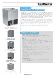
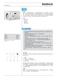
GENERAL DESCRIPTION1General descriptionThe <strong>HC</strong>V and <strong>HC</strong>H home ventilation units are primarily designed for 1 and 2 family houses.The units are supplied as packaged ventilation units complete with built-in demandcontroland a control panel. The home ventilation units are fitted with highly efficientcounter-flow heat exchangers which are optimised to a very high efficiency level thusachieving a very low specific fan power (SFP value) for the entire unit.For a quick selection you can use the selection chart below. The selection chart showsthe air volumes at a max. pressure loss of 100 Pa.<strong>HC</strong>V 3 model<strong>HC</strong>V 3<strong>HC</strong>V 4<strong>HC</strong>V 5<strong>HC</strong>H 5<strong>HC</strong>H 80 100 200 300 400 500 600Max. airflow at 100 Pa. ext. pressure (m 3 /h)<strong>HC</strong>V modelsThe <strong>HC</strong>V home ventilation units are vertical models designed for wall-mounting. Theyfulfil ventilation requirements of houses up to 260 m 2 , depending on national requirementsand the actual pressure loss in the installation.<strong>HC</strong>V 3 in standard 60x60 kitchenunitThe <strong>HC</strong>V 3 and <strong>HC</strong>V 4 units are perfect for concealed installation in standard 60x60 cmcupboard modules, e.g. in a modern utility room environment, where everything is hiddenbehind doors. All ducts are connected to the top of the unit and on this model it isalso possible to connect the supply duct to the base if ducts are to run beneath the floor.The <strong>HC</strong>V 5 unit is ideal for installation side-by-side with standard 60x60 cm cupboardmodules. If desired, the unit can be hidden behind a cupboard door, which can be facilitatedby reducing the depth of the unit to 560 mm using a special wall mounting availableas an accessory. On this model, all the duct connections are at the top of the unit.<strong>HC</strong>H modelsThe <strong>HC</strong>H home ventilation units are horizontal models designed to be fitted in the atticor on the floor of a plant room. They fulfil the ventilation requirements of houses up toapp. 475 m 2 , depending on national requirements and the actual pressure loss in theinstallation.Both <strong>HC</strong>H models have duct connections at the ends and service access at the front.Electrical connection is at the end of the unit facing the fresh air – right-hand – side. Theducts connected to the home (supply and extract) are always on the left-hand side ofthe unit. The condensation drain is located at the rear of the unit.<strong>HC</strong>H model- 5 -
1 GENERALDESCRIPTIONCertificatesThe <strong>Dantherm</strong> <strong>HC</strong> home ventilation units are certified for usage in passive houses byPassivHaus Institut in Darmstad, Germany. Furthermore they are DIBt LÜ-A20 certified byDeutsches Institut für Bautechnik in Berlin, Germany and tested in accordance with EN308 by IGE in Stuttgart, Germany. Hereby it is proven that the units fulfil the most severerequirements with regards to energy efficiency, air tightness, filter class, sound level, insulationclass, frost protection, safety and a lot more. Ask for the complete test reports at<strong>Dantherm</strong> Air Handling A/S.FunctionBoth the <strong>HC</strong>V and the <strong>HC</strong>H units are fitted as standard with automatic demand controls,which means that the relative air humidity in the house remains at a comfortable levelat all times. The demand control system employs a humidity sensor built into the unit,which constantly monitors the relative humidity of the air extracted from the house,whereupon the installation regulates the air volume as required. This secures an optimumindoor climate, at the same time minimising energy consumption when activitylevels in the house are low.Features• Demand-controlled ventilation with integrated humidity sensor• High efficiency – up to 95%• EC motors with extremely low energy consumption (low SFP)• Easy-to-install solution with pressure pipes for air volume measurementand adjustment on the unit.• <strong>HC</strong>V models are suitable for installation in 60x60 cm cupboardsCabinetThe <strong>HC</strong>V models are made from extruded polystyrene (EPS) components with a minimumwall thickness of 32 mm, while the <strong>HC</strong>H models are made with 40 mm thick walls.This high class insulation permits location of the units in rooms with temperatures aslow as –20°C.The <strong>HC</strong> series complies with European fire safety requirements as specified in EN 13501class E. The leakage rate of the unit (internal and external) is
GENERAL DESCRIPTION1FiltersAll models use 50 mm G4 compact filters as standard for both supply air and extract air.This will cater for the majority of air cleaning needs. The advantage of compact filtersis that they have a considerably larger filter surface area than fibrous filters and smallbag-filters. The filter thus works for longer and under normal conditions, it will not needchanging more often than twice a year, equivalent to the filter timer setting. If necessary,F7 filters (pollen filters) are available as accessories, which ensure that allergens do notenter the home through the ventilation system.Panel filtersInstallationMeasurement and adjustment of air volumes is done via pressure nozzles and potentiometerslocated behind the removable front panels of all models. A performance graphis adhered to the polystyrene front showing the pressure and air volumes the installermust use to determine the correct fan speeds. The label also has a space for the installerto write in the air volumes, the backpressure and fan speeds to which the system hasbeen adjusted. (See below).Adjustment labelPressure outlet on <strong>HC</strong>VAdjustment- 7 -
1 GENERALDESCRIPTIONOperationThe three wall-mounted models, <strong>HC</strong>V 3, <strong>HC</strong>V 4 and <strong>HC</strong>V 5 are operated via the integratedcontrol panel, the location of which is ergonomically correct when the unit isinstalled at a height of approx. 2 metres.Operation via control panelThe two horizontal models <strong>HC</strong>H 5 and <strong>HC</strong>H 8 are operated via the control panel , whichis connected to the ventilation unit by a cable (2 m). It is recommended that the panelbe fitted on a wall on the ground floor, e.g. in a back corridor or living room so that thestatus of the unit can be seen/heard and adjusted.Service and maintenanceIn general, the only regular maintenance required by <strong>HC</strong> products is to check/changethe air filters twice a year, when the alarm LED blinks yellow and the acoustic alarmbleeps once an hour.On <strong>HC</strong>V models, the user changes the filter by opening the top-hinged lid, changingthe filters and resetting the filter timer with the button next to the filters. On the <strong>HC</strong>Hmodels, the front panel is removed, after which the two filters can be changed and thefilter timer reset.Changing the <strong>HC</strong>V filterApart from changing the air filters and cleaning the outside of the unit, any other formof service will have to be carried out by qualified personnel. Local <strong>Dantherm</strong> techniciansand <strong>Dantherm</strong> partners are always available to solve any problem with the unitthat might arise.Changing the <strong>HC</strong>H filter- 8 -
CONTROL2CONTROLControl strategiesIn practice, the fact that the <strong>HC</strong> units have demand control automation means that younever need to touch the system once it has been installed and adjusted. However, itis possible to disable demand control and thus manually determine the fan speed ormanually activate the bypass module in order to get fresh air cooling here and now ifthe need should arise.Control panel (<strong>HC</strong>P 4)The installation is always secured against incorrect and uneconomical operation over alonger period. This is because several of the functions return to default after 4 hours. Thisprevents inconvenient excessive energy consumption if you e.g. forget that you have setthe unit to full speed or manual bypass. If you switch off the installation it automaticallyrestarts after 4 hours, so you can be sure that your home will be properly ventilated andthat condensation will not form in the ducts and in the unit.During adjustment, fan speed no. 3 is set on the control panel to the nominal air volumethe house requires under normal usage. This is done by adjusting the potentiometers(fan steps 46-91 out of 100 steps are available).Adjustment of air flow on thecontrol panelThe correlation between the four fan speeds on the control panel is as follows:• Fan speed 0 = both fans stopped for 4 hours.• Fan speed 1 = 50* steps slower than fan speed 3• Fan speed 2 = 25* steps slower than fan speed 3• Fan speed 3 = Nominal air change, adjustment using potentiometers• Fan speed 4 = Max.* fan speed*These factory settings can be adjusted from the remote controlWhen the installation is set to demand control it never runs faster than the adjusted airvolume at step 3. This avoids unnecessary inconvenience in special situations duringwhich external factors would otherwise cause the installation to run at maximum airvolume.- 9 -
2 CONTROLControl panelThe drawing below shows the buttons, LEDs and sound outlets on the control panelwhich is included with the unit and the remote control which is an optional accessory.Status LED:Green = OKYellow = change filterRed = system faultNominal air volumeFan step 3 adjusted usingpotentiometers on rear ofthe control panelControl panel, <strong>HC</strong>P 4Acoustic alarmManual bypassManual control offan speedFan speed 01234Fire place functionAutomatic demand controlFan speed (0)123Current fan speedShown for 2 mins.after actuationWireless remote controlWith an optional remote control the user gets access to week program operation, awayoperation, night operation, and reading of outdoor temperature, supply air temperature,extract air temperature, supply air temperature, extract air temperature and room temperature,air humidity and CO2 levels.2 menu levelsUser menuInstaller menuWireless remote control, HRC 2(accessory)Acoustic alarmDisplay with iconsRead actual temperatures, relative humidity,CO2 level, operation and filter status andalarms, if any5-way navigation buttonSelection of operation andcontrol.Adjustment of setpoints- 10 -
CONTROL2Bypass-module for <strong>HC</strong>HBypass coolingAutomatic bypass functionAll models in the <strong>HC</strong> series are fitted with a bypass module, with the exception of the<strong>HC</strong>V 3 and <strong>HC</strong>V 4. The bypass module is regulated automatically and exploits the coldoutdoor air to cool down the home, e.g. after a hot summer’s day, when the night timetemperature outdoors falls below the temperature of the house. The bypass moduleleads all the hot exhaust air past the heat exchanger in order to achieve the best possiblecooling effect. In order for the unit automatically to open the bypass module, the hotextract temperature (T3) must be ≥24°C*, and the outdoor air (T1) ≥15°C*. The outdoorair (T1) must also be 2°C colder than the hot extract temperature (T3). *These factorysettings can be adjusted from the remote control.T2 Supply airT3 Extract airT4 Exhaust airT1 Outdoor airManual bypass functionIn addition to the system providing cooling by means of the automatic bypass function,there is also a manual bypass function which can be activated by the user wheneverrequired. This function keeps the bypass module open for 6 hours, on condition that thewarm extract temperature (T3) is ≥15°C, the outdoor temperature (T1) is above 2°C andthe outdoor air (T1) is 2°C colder than the hot extract temperature (T3).Frost protection of the heat exchangerThe intelligent control system of the <strong>HC</strong> systems ensures that the heat exchanger doesnot ice up. Frost protection is activated if the exhaust air temperature (T4) is < +2°C,which will usually occur when the outdoor air temperature (T1) falls below approx. –6°C.When the exhaust temperature (T4) falls to +2°C, the system reduces the volume of supplyair (T2) so that the final exhaust temperature (T4) is maintained at minimum +2°C. Ifit is particularly cold, the supply air volume will be turned right down to 0 m3/h for shortintervals in order to keep the heat exchanger frost-free. If the outdoor air temperature(T1) falls below < -13°C for more than five minutes, the system stops completely for 30mins. in order to stop it icing up.In areas where the outdoor temperatures often is lower than -6°C, we recommend tomount pre-heating. In other areas, where the outdoor temperature may fall below -10°C, preheating is a must for obtaining a balanced and reliable solution.Frost protection of water based heating coilIn order to protect the water based after heating coil (when mounted) against frost, theunit stops for 30 min., if the supply air temperature (T2) is < +5°C.Filter controlBecause backpressure in the filter is expected to increase and thus reduce air volumesduring the period preceding a filter change, this is compensated for by the two fans runningfaster and faster until the filter alarm sounds/lights up and the filter timer is reset.- 11 -
3 TECHNICALDATATECHNICAL DATAModel <strong>HC</strong>V 3 <strong>HC</strong>V 4 <strong>HC</strong>V 5 <strong>HC</strong>H 5 <strong>HC</strong>H 8PerformanceMax. air flow at 100 Pa ext. pressure m 3 /h 230 275 375 375 530Heat exchanger type<strong>Dantherm</strong> Alu. counterflow heat exchangerTemperature efficiency Up to 95% 1 )Bypass No YesFilter class supply/exhaust, standardG4/G4Surrounding temperature where the unit is installed °C +10 to +50 -20 to +50Operational temperature range without pre-heating °C -13 2 ) to + 50Operational temperature range with pre-heating °C - 30 to + 50CabinetHeight mm 1005 1005 1055 600 600Width mm 530 530 590 1180 1180Depth (Standard mounting rail/rail for plan mounting) mm 434/419 434/419 584/569 580 780Duct connection mm 125 125 160 160 250Weight, unit kg 33 32 45 52 70Weight including packaging kg 41 42 57 66 84H: 675 H: 675 H: 735 H: 750 H: 775Dimensions including packaging and pallet (HxWxD) mm W: 1070 W: 1070 W: 1120 W: 1210 W: 1200D: 435 D: 435 D: 600 D: 610 D: 800Outer cabinet materialAluzinkColour RAL 9010 Aluzink greyCabinet insulation, polystyrene mm 32 40Insulation factor, cabinet W/m 2 x °K 0,97 0,78Fire classification, polystyrene cabinetDIN 4102 class B1Fire classification, the whole unitEN 13501 class EProtection class IP 20Electrical dataIntegrated control panel <strong>HC</strong>P 4 in front Yes NoSeparate <strong>HC</strong>P 4 control panel included + 2 m cable No YesSupply voltage1x230 V, 50 HzMax. current consumption, without pre- and after-heat A 0,4 0,4 0,7 0,7 1,1Max. power consumption, without pre- and after-heat W 88 88 154 154 2461) Condensing operation.2) We recommend preheating at temperatures under -6°C to ensure a balanced operation.- 12 -
TECHNICAL DATA3<strong>HC</strong>V 3 Sound dataFlow Pressure Measure Frequency band sound power Total sound power Sound pressurem 3 /h Pa Point Lw dB(A) Lw dB(A) Standard room*63Hz 125Hz 250Hz 500Hz 1000Hz 2000Hz 4000Hz Lp dB(A)Supply air duct 34 40 43 44 36 27 19 5770 Extract air duct 35 38 40 44 41 33 24 56140Cabinet 47Supply air duct 36 42 45 47 38 29 21 59100 Extract air duct 37 40 43 47 43 33 26 58Cabinet 20 32 39 42 39 34 24 49Supply air duct 38 42 47 50 48 42 31 61180 100 Extract air duct 38 43 50 51 48 42 31 61Cabinet 38 41 45 48 46 40 29 55* Standard room = room with 10 m 2 floor, 2,4 m ceiling height, mean absorption 0,2.<strong>HC</strong>V 4 Sound dataFlow Pressure Measure Frequency band sound power Total sound power Sound pressurem 3 /h Pa Point Lw dB(A) Lw dB(A) Standard room*63Hz 125Hz 250Hz 500Hz 1000Hz 2000Hz 4000Hz 8000Hz Lp dB(A)Supply air duct 20 30 41 42 38 30 19 18 4670 Extract air duct 18 30 41 41 30 26 18 18 44126Cabinet 27 34 48 46 43 40 27 19 47Supply air duct 22 32 46 45 39 32 21 18 49100 Extract air duct 22 33 43 42 32 27 19 18 46Cabinet 32 38 50 49 46 41 32 22 50Supply air duct 23 31 43 46 41 33 22 18 4970 Extract air duct 26 31 42 43 33 29 21 18 46162Cabinet 38 40 49 54 52 44 33 20 53Supply air duct 28 33 44 48 43 35 23 18 51100 Extract air duct 29 34 44 51 37 31 23 18 52Exhaust air duct 32 43 46 46 38 31 31 19 50Cabinet 46 42 47 56 52 44 34 21 55Supply air duct 28 33 44 54 46 37 28 18 5570 Extract air duct 27 33 43 52 39 33 27 18 52216Cabinet 34 39 47 57 54 49 39 24 57Supply air duct 28 35 45 55 46 38 29 18 56100 Extract air duct 32 34 44 52 40 34 28 18 53Cabinet 40 38 47 60 53 48 39 23 56* Standard room = room with 10 m 2 floor, 2,4 m ceiling height, mean absorption 0,2.- 13 -
3 TECHNICALDATA<strong>HC</strong>V 5 Sound dataFlow Pressure Measure Frequency band sound power Total sound power Sound pressurem 3 /h Pa Point Lw dB(A) Lw dB(A) Standard room*63Hz 125Hz 250Hz 500Hz 1000Hz 2000Hz 4000Hz 8000Hz Lp dB(A)Supply air duct 20 30 34 36 23 19 17 18 40126 50 Extract air duct 16 31 37 36 29 21 17 18 40Cabinet 18 32 37 38 37 32 21 19 39Supply air duct 23 33 35 40 32 24 18 18 4370 Extract air duct 20 33 44 39 34 26 18 18 46162Cabinet 22 34 42 41 42 38 24 19 44Supply air duct 25 36 42 42 34 28 18 18 46100 Extract air duct 21 33 43 41 35 28 18 18 46Cabinet 25 36 45 44 44 41 26 19 46Supply air duct 25 34 42 42 35 28 19 18 4670 Extract air duct 22 34 44 43 37 31 20 18 47Cabinet 24 35 47 44 45 42 29 20 47216 Supply air duct 26 36 43 44 36 30 20 18 47100 Extract air duct 23 34 45 44 33 32 20 18 48Exhaust air duct 35 42 59 49 49 44 33 20 60Cabinet 25 36 50 46 46 44 30 20 49Supply air duct 27 36 45 45 38 31 21 18 49250 100 Extract air duct 24 37 47 45 40 34 22 18 50Cabinet 26 38 53 47 48 46 33 22 53* Standard room = room with 10 m 2 floor, 2,4 m ceiling height, mean absorption 0,2.- 14 -
TECHNICAL DATA3<strong>HC</strong>H 5 Sound dataFlow Pressure Measure Frequency band sound power Total sound power Sound pressurem 3 /h Pa Point Lw dB(A) Lw dB(A) Standard room*63Hz 125Hz 250Hz 500Hz 1000Hz 2000Hz 4000Hz 8000Hz Lp dB(A)Supply air duct 23 34 40 36 29 25 17 18 4270 Extract air duct 23 33 39 37 29 24 18 18 42162Cabinet 22 31 39 41 31 29 23 21 40Supply air duct 25 35 43 38 31 28 18 18 45100 Extract air duct 25 36 42 39 40 25 17 18 45Cabinet 23 34 41 42 33 31 24 21 41Supply air duct 26 36 44 39 33 30 19 18 4670 Extract air duct 28 36 43 41 34 29 18 18 46216Cabinet 28 35 45 44 37 35 27 21 45Supply air duct 26 37 44 40 34 31 19 18 47100 Extract air duct 27 37 45 42 35 30 19 18 48Exhaust air duct 34 43 52 52 47 51 38 21 57Cabinet 26 34 46 45 38 36 28 21 46Supply air duct 28 39 46 42 37 33 21 18 49250 100 Extract air duct 30 39 48 45 38 33 20 18 50Cabinet 28 36 50 48 41 39 32 22 49* Standard room = room with 10 m 2 floor, 2,4 m ceiling height, mean absorption 0,2.<strong>HC</strong>H 8 Sound dataFlow Pressure Measure Frequency band sound power Total sound power Sound pressurem 3 /h Pa Point Lw dB(A) Lw dB(A) Standard room*63Hz 125Hz 250Hz 500Hz 1000Hz 2000Hz 4000Hz 8000Hz Lp dB(A)Supply air duct 44 51 56 50 43 38 23 7 63350 100 Extract air duct 41 47 48 46 41 36 23 2 59Cabinet 26 37 52 43 40 37 23 17 52Supply air duct 39 48 62 55 52 50 37 22 67450 100 Extract air duct 39 47 61 55 53 48 37 20 66Cabinet 38 46 60 52 50 47 36 22 61* Standard room = room with 10 m 2 floor, 2,4 m ceiling height, mean absorption 0,2.- 15 -
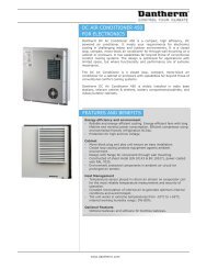
3 TECHNICALDATA<strong>HC</strong>V 3 Capacity & SFP curves(with radial fans, G4/G4 filters)<strong>HC</strong>V 3 - capacity & SFP curves(with radial fans, G4/G4 filters)350325Step 100 = Fan speed 100%SFP [Wh/m3] & [j/m3], both fans300Step 100275250Ext. pressure drop [Pa]Ext. pressure drop (Pa)225200175150125Step 64Step 50Step 81SFP 0,45/1620 (PHI)SFP 0,39/140010075Step 3650250Step 12 SFP 0,33/1200SFP 0,22/800 SFP 0,28/10000 25 50 75 100 125 150 175 200 225 250 275 300Airflow Airflow [m3/h] (m 3 /h)<strong>HC</strong>V 3 Temperature efficiency95,0Temperature efficiency withcondensate.Extract air = 25°C/55%RHOutdoor air = -10°C/50%RHBalanced mass flow.Temperature efficiency (DiBt).Extract air = 21°C/37%RHOutdoor air = -3°C/85%RHBalanced mass flow.Temperature efficiency(Passivhaus)Extract air = 21°C/32%RHOutdoor air = +4°C/90%RHBalanced mass flow.Temperature efficiency (%)90,085,080,075,050 70 90 110 130 150 170Airflow (m 3 /h)- 16 -
TECHNICAL DATA3<strong>HC</strong>V 4 Capacity & SFP curves(with Radial 133 mm fans, G4/G4 filters)350Step 100 = Fan speed 100%325300<strong>HC</strong>V4 - capacity & SFP curves(with Radial 133 mm fans, G4/G4 filters)Step 100SFP [Wh/m3] & [j/m3], both fans275Ext. pressure drop (Pa)Ext. pressure drop (Pa)250225200175150125100755025Step 85Step 70Step 58Step 46Step 33Step 21SFP 0,45/1620 (PHI)SFP 0,39/1400SFP 0,33/1200SFP 0,28/1000SFP 0,22/80000 25 50 75 100 125 150 175 200 225 250 275 300Airflow Airflow (m3/h)3 /h)<strong>HC</strong>V 4 Temperature efficiency100,0Temperature efficiency withcondensate.Extract air = 25°C/55%RHOutdoor air = -10°C/50%RHBalanced mass flow.Temperature efficiency (EN308).Extract air = 25°C/25%RHOutdoor air = +5°C/95%RHBalanced mass flow.Temperature efficiency (%)95,090,085,080,075,050 70 90 110 130 150 170 190 210 230 250Airflow (m 3 /h)- 17 -
3 TECHNICALDATA<strong>HC</strong>V 5 Capacity & SFP curves(with RadiCal fans, G4/G4 filters)350Step 100 = Fan speed 100%325<strong>HC</strong>V 5 - capacity & SFP curves(with RadiCal fans, G4/G4 filters)SFP [Wh/m3] & [j/m3], both fans300Step 100275Ext. pressure drop (Pa) [Pa]250225200175150125Step 58Step 70Step 85SFP 0,45/1620 (PHI)SFP 0,39/14001007550250Step 46Step 33SFP 0,33/1200Step 21SFP 0,28/1000SFP 0,22/8000 25 50 75 100 125 150 175 200 225 250 275 300 325 350 375 400 425 450Mean airflow Mean [m3/h] airflow (m 3 /h)Supply air = Supply mean airflow = mean + 5%, airflow Extract +5%, air Extract = mean air = mean airflow airflow - 5% -5%<strong>HC</strong>V 5 Temperature efficiency95,0Temperature efficiency withcondensate.Extract air = 25°C/55%RHOutdoor air = -10°C/50%RHBalanced mass flow.Temperature efficiency (DiBt).Extract air = 21°C/37%RHOutdoor air = -3°C/85%RHBalanced mass flow.Temperature efficiency(Passivhaus)Extract air = 21°C/32%RHOutdoor air = +4°C/90%RHBalanced mass flow.Temperature efficiency (%)90,085,080,075,080 120 160 200 240 280Airflow (m 3 /h)- 18 -
TECHNICAL DATA3<strong>HC</strong>H 5 Capacity & SFP curves(with RadiCal fans, G4/G4 filters)350Step 100 = Fan speed 100%325300275250<strong>HC</strong>H 5 - capacity & SFP curves(with RadiCal fans, G4/G4 filters)Step 85Step 100SFP 0,45/1620 (PHI)SFP [Wh/m3] & [ j/m3], both fansExt. pressure Ext. pressure drop [Pa] drop (Pa)225200175150125100755025Step 70Step 58Step 46Step 33Step 21SFP 0,39/1400SFP 0,33/1200SFP 0,28/1000SFP 0,22/80000 25 50 75 100 125 150 175 200 225 250 275 300 325 350 375 400 425Mean airflow Mean [m3/h] airflow (m 3 /h)Supply air = mean Supply airflow = + mean 5%, airflow Extract +5%, air = Extract mean air airflow = mean - 5 airflow % -5%<strong>HC</strong>H 5 Temperature efficiency95,0Temperature efficiency withcondensate.Extract air = 25°C/55%RHOutdoor air = -10°C/50%RHBalanced mass flow.Temperature efficiency (DiBt).Extract air = 21°C/37%RHOutdoor air = -3°C/85%RHBalanced mass flow.Temperature efficiency(Passivhaus)Extract air = 21°C/32%RHOutdoor air = +4°C/90%RHBalanced mass flow.Temperature efficiency (%)90,085,080,075,080 120 160 200 240 280Airflow (m 3 /h)- 19 -
3 TECHNICALDATA<strong>HC</strong>H 8 Capacity & SFP curves(with radial fans, G4/G4 filters)<strong>HC</strong>H 8 - capacity & SFP curves(with radial fans, G4/G4 filers)350325Step 100 = Fan speed 100%Step 100SFP [Wh/m3] & [j/m3], both fans300275250Step 85Ext. pressure drop [Pa]Ext. pressure drop (Pa)225200175150125100Step 46Step 70Step 58SFP 0,45/1620 (PHI)SFP 0,39/140075Step 33SFP 0,33/12005025Step 21SFP 0,22/800SFP 0,28/100000 50 100 150 200 250 300 350 400 450 500 550 600Mean airflow Mean airflow (m 3 /h) [m3/h]Supply Supply air = air mean = mean airflow airflow +5%, Extract + 5%, air Extract = mean air airflow = mean -5% airflow - 5 %<strong>HC</strong>H 8 Temperature efficiency95,0Temperature efficiency withcondensate.Extract air = 25°C/55%RHOutdoor air = -10°C/50%RHBalanced mass flow.Temperature efficiency (DiBt).Extract air = 21°C/37%RHOutdoor air = -3°C/85%RHBalanced mass flow.Temperature efficiency(Passivhaus)Extract air = 21°C/32%RHOutdoor air = +4°C/90%RHBalanced mass flow.Temperature efficiency (%)90,085,080,075,0120 180 240 300 360 420 480Airflow (m 3 /h)- 20 -
TECHNICAL DATA3<strong>HC</strong>V 3 DimensionsT2 Supply air bottom419Ø125216283981082100598T2 Supply air topT3 Extract airT4 Exhaust airT1 Outdoor airØ125438530437,526593- 21 -
3 TECHNICALDATA<strong>HC</strong>V 4 Dimensions1039103910051005209209T2 Supply air topT3 Extract airT4 Exhaust airT1 Outdoor air162 162151 151179 179108 108416416 126126240282 240282110147 110147530 530- 22 -
TECHNICAL DATA3<strong>HC</strong>V 5 DimensionsT2 Supply airT3 Extract airT4 Exhaust airT1 Outdoor air131 131Fits Fits 3/4" 3/4" drain drain hose hose590 590480 480295 295110 110255374 2553741121121611615665661087108710551055126126- 23 -
3 TECHNICALDATA<strong>HC</strong>H 5 DimensionsT1 Outdoor airT3 Extract airT4 Exhaust airT2 Supply air- 24 -
TECHNICAL DATA3<strong>HC</strong>H 8 DimensionsT1 Outdoor airT3 Extract airT4 Exhaust airT2 Supply air- 25 -
4 ACCESSORIESACCESSORIESWall mounting railMounting rail for plan installation of <strong>HC</strong>V 5 behind the door in a cupboard. With this railthe installation depth will be reduced. Insulation tape (50x3 mm), vibration damper, andu-profile (19x5 mm) are included. Dimension: 526 mm x 30 mm.Wall mounting railfor plan installationSiphon trap kitSiphon trap kit including 2 m ¾” armed hose and glands.Siphon trap kitHeat cable, 3 mHeat cable, 230V, 10W/m, including. 5°C thermostat for frost protection of drain.Heat cableCommunication cableCommunication cable, 30 m extension, with plug for connection of control panel to the<strong>HC</strong>H/<strong>HC</strong>V unit.Communication cable- 26 -
ACCESSORIES4Wireless remote controlWireless remote control, HRC 2The remote control gives access to:• manual operation• automatic demand-control• week program operation• away operation when you are absent for a longer period• night operation• reading of outdoor temperature, supply and extract air temperature,room temperature, relative humidity and CO2 level• installer menu for adjustment and fault-findingAccessory control HAC 1Accessory control with connection of heating coils, cooling coils, geothermal collector,duct damper, stop function, fire thermostat, CO2 sensor, hygrostat and alarms, incl. 5 mcable.Accessory controlPower supply 230VAC – 24VDC, for duct controlPower supply to be mounted in the accessory control if the ventilation unit is controllingthe duct damper.Power supplyHygrostat, Sauter HSC 120 F001The hygrostat is connected to the accessory control in case that a higher air change rateis required in rooms with high humidity.HygrostatCO2 sensorCO2 sensorThe CO2 sensor is connected to the accessory control if the air change has to be controlledin accordance with the CO2 level in a given room.- 27 -
4 ACCESSORIESHeating coils for electricityThe electric heating coils are designed for installation in the supply or extract air duct.The heating coil is provided with duct connections with a rubber sealing gasket. Theheating coil is not suitable for outdoor installation. The control current is connected tothe accessory control HAC 1. Connection to supply voltage 230V is made separately.Electric pre-/after heating coil, 0-10V controlled by the accessory controlThe heating coil is controlled by a stepless regulation via the accessory control HAC 1.Electric pre-/after heating coil, direct control by the built-in thermostatThe heating coil is controlled by the built-in thermostat. Both heating coils are suppliedwith a duct sensor.Both heating coils are supplied with a duct sensor.Electric pre-/afterheating coil 0-10V.Capacity, dimensions and weight<strong>HC</strong>V 3 <strong>HC</strong>V 4 <strong>HC</strong>V 5 <strong>HC</strong>H 5 <strong>HC</strong>H 8Air volume m 3 /h 180 220 300 300 450Heat output kW 0,9 0,9 1,2 1,2 1,8Temperature rise °C 16,8 13,7 14,2 14,2 13,4Power consumption, 1x230V A 4,1 4,1 5,5 5,5 8,2Duct connection Ø mm 125 125 160 160 250Weight Kg 3,0 3,0 3,5 3,5 5,0The electric heating coils are un-finned and therefore the resulting air pressure loss isnegligible.278Ø+17Electric pre-/afterheating coil,direct control42 4282AIRØ375- 28 -
ACCESSORIES4Water heating coilsThe water heating coil kit includes 2RR, 2-way water valve, 0-10V servo motor, 230/24VACtrafo, duct sensor and tube sensor for frost protection. It is controlled by the accessorycontrol HAC 1.Water heating coil<strong>HC</strong>V 3 / <strong>HC</strong>V 4 Max. capacity Supply air temperature 21°C(CWW 125-2-2.5) 80°C/60°C 60°C/40°C 80°C/60°C 60°C/40°CAir volume m 3 /h 85 150 215 85 150 215 85 150 215 85 150 215Air temp. out* °C 40 36 34 28 25 23 21 21 21 21 21 21Pressure loss Pa 11 28 51 11 28 51 11 28 51 11 28 51Capacity kW 0,7 1,1 1,4 0,4 0,5 0,6 0,2 0,3 0,5 0,2 0,3 0,5Water flow L/h 36 36 72 36 36 36 9 10 23 17 22 28Pressure loss, max. KPa 0,5 0,5 1 0,5 0,5 0,5 0,2 0,2 0,4 0,3 0,4 0,5Servo motor2-way water valve<strong>HC</strong>V 5/<strong>HC</strong>H 5 Max. capacity Supply air temperature 21°C(CWW 160-2-2.5) 80°C/60°C 60°C/40°C 80°C/60°C 60°C/40°CAir volume m 3 /h 145 250 355 145 250 355 145 250 355 145 250 355Air temp. out* °C 47 43 40 33 31 29 21 21 21 21 21 21Pressure loss Pa 6 15 27 6 15 27 6 15 27 6 15 27Capacity kW 1,6 2,4 3,0 0,9 1,3 1,7 0,3 0,5 0,7 0,3 0,5 0,7Water flow L/h 72 108 144 36 72 72 14 24 35 12 28 30Pressure loss, max. KPa 1 3 4 0,5 1 2 0,2 0,4 0,5 0,1 0,4 0,5230/24 V AC trafo<strong>HC</strong>H 8 Max. capacity Supply air temperature 21°C(CWW 250-2-2.5) 80°C/60°C 60°C/40°C 80°C/60°C 60°C/40°CAir volume m 3 /h 360 630 360 630 360 630 360 630Air temp. out* °C 44 40 31 29 21 21 21 21Pressure loss Pa 10 25 10 25 10 25 10 25Capacity kW 3,6 5,3 2,0 3,0 0,74 1,29 0,74 1,28Water flow L/h 144 252 108 144 30 61 40 61Pressure loss, max. KPa 1 3 1 2 0,5 1,0 0,7 1,0*Air in 15°C- 29 -
4 ACCESSORIESWater heating coils, continuedDimensions and weightØd B H Ødy F G K L WeightmmKg<strong>HC</strong>V 3 / <strong>HC</strong>V 4CWW 125-2-2.5 125 238 180 10 137 40 276 356 3,5<strong>HC</strong>V 5 / <strong>HC</strong>H 5CWW 160-2-2.5 160 313 255 10 212 40 276 356 5,4<strong>HC</strong>H 8CWW 250-2-2.5 250 398 330 10 250 40 276 356 7,7ØdyBFB+8HGKGLPanel filtersPanel filters are supplied as a set with either two G4 filters or one G4 filter and one F7filter. G4 is standard. F7 filters can be used on the supply air as a pollen filter.Filters- 30 -
- 31 -
dantherm.comELECTRONICS COOLING DEHUMIDIFICATION VENTILATION MOBILE HEATING AND COOLING<strong>Dantherm</strong> is a market-leading supplier of energy-efficient climate control solutionsfor customers across the globe. Our subsidiaries in Norway, Sweden, Germany,the UK, the US and China and our representative office in Russia unite approx. 600employees. We operate in the following four main business areas:Electronics cooling:Climate control for electronics and battery cooling in radio base stations and otherTelecom infrastructure. Telecom customers include network suppliers and networkoperators.<strong>Dantherm</strong> Air Handling A/SMarienlystvej 65DK-7800 Skive, DenmarkTel. +45 96 14 37 00Fax +45 96 14 38 20info@dantherm.comDehumidification:Mobile and stationary dehumidifiers for drying buildings and for use in privatepools and wellness centres.<strong>Ventilation</strong>:Large ventilation systems used in swimming pools and buildings such as shoppingcentres and cinemas requiring frequent air change. The range also includes domesticventilation products based on high-performance heat exchangers.Mobile heating and cooling:Products for heating or cooling of tents and equipment used by the armed forcesand aid organisations. The customers are primarily the armed forces in NATO countriesas well as tent and container manufacturers.02.13. Thorvig Tryk, Skive