GB - Duplomatic
GB - Duplomatic
GB - Duplomatic

You also want an ePaper? Increase the reach of your titles
YUMPU automatically turns print PDFs into web optimized ePapers that Google loves.
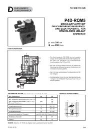
DSE3JSERIES 203 - CHARACTERISTIC CURVES (obtained with mineral oil with viscosity of 36 cSt at 50°C and with digital integrated electronics)Typical flow rate curves at constant ∆p related to the reference signal and measured for theavailable spools. The ∆p values are measured between P and T valve ports.The curves are obtained after linearization in factory of the characteristic curve through the digitalamplifier.SPOOL Z04Command value [%]SPOOL Z12SPOOLS A12 - C12Command value [%]Command value [%]SPOOL Z30SPOOLS A30 - C30Command value [%]Command value [%]83 230/112 ED 3/10
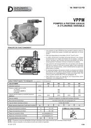
DSE3JSERIES 20Z SPOOLS - PRESSURE GAINZ*FS SPOOLS - FAIL SAFE FEATUREReference signal [%]The diagram shows the valve pressure gain, expressedas % of the ratio between the port pressure variation inA or B (∆p AB) and the P system pressure, according tothe reference signal.In practice, the pressure gain states the valve reactiontowards external disturbances aimed at changing theactuator position.Flow P→B / A→T with valve in fail safe position, depending on theincoming pressure.When a power failure (enabling OFF) occurs, the valve moves in ‘fail safe’position by maintaining a minimum flow that allows the actuator to returnslowly to a safety position.During the black-out the centering springs retain the spool in fail safeposition.4 - RESPONSE TIME (obtained with mineral oil with viscosity of 36 cSt at 50°C and with digital integrated electronics and ∆p (P-T) 10 bar)FREQUENCY RESPONSE (SPOOL Z)Amplitude [dB]SignalPhase lag [degrees]Frequency [Hz]RESPONSE TIME83 230/112 ED 4/10
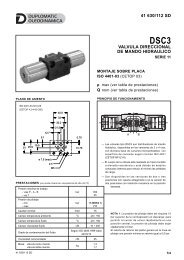
DSE3JSERIES 205 - ELECTRICAL CHARACTERISTICS5.1 - Digital integrated electronicsThe proportional valve is controlled by a digital amplifier (driver),which incorporates a microprocessor that controls, via software, allthe valve functions, such as:- continuous converting of the voltage reference signal (E0) or ofthe current reference signal (E1) in a digital value- generation of up and down ramps- gains limit- compensation of the dead band- protection of the solenoid outputs against possible short circuitsThe digital driver enables the valve to reach better performancescompared to the analogic version, such as:- reduced response times- optimization and reproducibility of the characteristic curve,optimised in factory for each valve- complete interchangeability in case of valve replacement- possibility to set, via software, the functional parameters- possibility to perform a diagnostic program by means of the LINconnection- high immunity to electromagnetic troublesWe deliver the DSE3J with these standard settings:UP/DOWN ramp at minimum value, no deadband compensation,max valve opening (100% of spool stroke). It is possible tocustomize these parameters using the special kit, to be orderedseparately (see par 7).5.2 - Functional block diagram1 Valve with proportional solenoids 3 Digital card2 Electronics envelope 4 Main connector5.3 - Electrical characteristicsNOMINAL VOLTAGEV DC24 (from 19 to 35 VDC, ripple max 3 Vpp)external fuse 5A (fast), max current 3AABSORBED POWER W 70MAXIMUM CURRENT A 2.6DUTY CYCLE 100%VOLTAGE SIGNAL (E0) V DC ±10 (Impedance Ri > 50KΩ)CURRENT SIGNAL (E1) mA 4 ÷ 20 (Impedance Ri = 500 Ω)ALARMSCOMMUNICATIONOverload and electronics overheating, LVDT sensor error, cablebreakdown or power failure or < 4mA.LIN-bus Interface (with the optional kit)MAIN CONNECTOR 7 - pin MIL-C-5015-G (DIN 43563)ELECTROMAGNETIC COMPATIBILITY (EMC)emissions CEI EN 61000-6-4immunity CEI EN 61000-6-2PROTECTION AGAINST ATMOSPHERIC AGENTSAccording to 2004/108/CE standardsIP65 / IP67 (CEI EN 60529 standards)83 230/112 ED 5/10
DSE3JSERIES 206 - OPERATING MODALITIESThe digital driver of DSE3J valve is available in two versions, with voltage or current reference signal.6.1 - Version with voltage reference signal (E0)This is the most common version; it makes the valve completely interchangeable with the traditional proportional valves with analogic typeintegrated electronics. The valve has only to be connected as indicated below. This version doesn’t allow the setting of the valve parameters,for example the ramps must be performed in the PLC program, as well as the reference signal limit.Connection scheme E0Pin Values Function NOTESA 24 V DC Voltage from 19 to 35 V DC (ripple max 3 Vpp) (see NOTE 1)B 0 V Power supply (zero) 0 VC 24 V DC Valve Enable NOTE 2D ± 10 V Differential input Impedance R i > 50 kΩ (see NOTE 3)E 0 V Differential input ---F6 - 10V o2 - 6 -10VMonitor feedback orLin commsee NOTE 4PE GND Protective ground ---6.2 - Version with current reference signal (E1)The reference signal is supplied in current 4 - 20 mA. With the 12 mA signal the valve is in central position, with the 20 mA signal the valveperforms the configuration P-A and B-T, while with 4 mA the configuration is P-B and A-T. For “SA” single solenoid valves, with reference 20mA to pin D, the valve full opening is P-B and A-T, while with 4 mA the valve is at rest. If the current to solenoid is lower, than the card shows aBREAKDOWN CABLE error. To reset the error is sufficient to restore the current 4mA.Connection scheme E1Pin Values Function NOTESA 24 V DC Voltage from 19 to 35 V DC (ripple max 3 Vpp) (see NOTE 1)B 0 V Power supply (zero) 0 VC 24 V DC Valve Enable NOTE 2D 4 ÷ 20 mA Input signal Impedance R i > 500 kΩE 0 V Zero reference ---F6 - 10V o2 - 6 -10VMonitor point orLin commsee NOTE 4PE GND Protective ground ---NOTE 1: preview on the Pin A (24 VDC) an external fuse for protecting electronics. Fuse characteristics: 5A/50V type fast.NOTE 2: preview 24V DC on the PIN C to activate the card power stage.NOTE 3: The input signal is differential type on E0 version only. For double solenoid valves, with positive reference signal connected to pin D,the valve opening is P - A and B - T. With zero reference signal the valve is in central position. For “SA” single solenoid valves, with positivereference to pin D, the valve opening is P-B and A-T. The spool stroke is proportional to U D - U E .If only one input signal (single-end) is available, the pin B (0V power supply) and the pin E (0V reference signal) must be connected through ajumper and both connected to GND, electric panel side.83 230/112 ED6/10
DSE3JSERIES 20NOTE 4: This value changes, as shown in the table below. When MONITOR function is enabled and the card is enabled, read the test point pinF in relation to pin B (0V). When detect a failure or error of the sensor LVDT, the drive bring the valve back in central position and locks it. Inthis condition the pin F, referring to the pin B, indicates 0V DC output. To reset the fault, the card must be disabled and re-enable. When thecard is disabled, the pin F referred to the pin B shows 2.7V DC output: this value is given by the voltage of the LIN bus communication and notby the MONITOR value.double solenoid valvessingle solenoid valvecommand (Pin D) Pin F command (Pin D) Pin F-10 V 10 V - -0 V 6 V 0 V 6 V+10 V 2 V +10 V 10 VNOTE for the wiring: connections must be made via the 7-pin plug mounted on the amplifier. Recommended cable sizes are 0,75 mm 2 forcables up to 20m and 1,00 mm 2 for cables up to 40m, for power supply. The signal cables must be 0,50 mm 2 . A suitable cable would have7 cores, a separate screen for the signal wires and an overall screen.7 - OPTIONAL KIT LINPC-USB/10The kit (to be ordered separately, code 3898501001) includes control box with 7 poles connector, USB PC cable (1.8 m length), software forcard configuration. The software is Microsoft XP © compliant.The box has three main functions:- It can be used to read the values from the external command (PLC, etc. ..) to the valve. In this case, the box simply acts as monitor throughpoints of measurement.- It may exclude the command from the PLC and controls the valve, choosing the direction and speed of movement (keys gr.2 and 4). Thisway you can test the response of the valve control input, and diagnose failures, malfunctions, simulating the valve working.- The control box acts as interface between PC and electronic card (key 3) to allow customization of the parameters via software.For more detailed information on the use of the box, see the documentation on the software CD.CONTROL BOXfrom the system1 Test points2 Keys for control of valvemovements.3 Switch LinBus/Monitor4 Enable Switchto the valve5 Leds6 RS232 connection to PCcable length = 2 mt7 Main connector7.1 - Programming the parameters via LIN BusThe software included in the kit allows the customization of the following parameters:Deadband compensationYou can change the mechanical spool overlap by adjusting the parameters V: MINA and V MINB.Gain AdjustmentYou can change the parameters V and V MAXA: MAXB, which restrict the spool opening for positive and negative values of the referencesignal.AINW: W command input scalingThis command allows to scale the input signal and determine whether the input is enabled for signals in voltage or in current.V: TRIGGERValue in percentage by which you activate the deadband function of V: MinA and V: minB83 230/112 ED7/10
DSE3JSERIES 20RampsRamps are divided into four quadrants and can be customized bysetting the parameters 1Q, 2Q, 3Q and 4Q. They define the timevariation of current in the solenoid in reference to input command.range: 1 ÷ 60000 ms.1Q2Q3Q4Q7.2 - Wiring scheme of Lin/Bus box1 USB connector2 Main connection fromthe system3 Lin/Bus connection4 7 poles connection tocommand the valve.8 - HYDRAULIC FLUIDSUse mineral oil-based hydraulic fluids HL or HM type, according to ISO 6743-4. For these fluids, use NBR seals. For fluids HFDR type(phosphate esters) use FPM seals (code V). For the use of other kinds of fluid such as HFA, HFB, HFC, please consult our technicaldepartment.Using fluids at temperatures higher than 80 °C causes a faster degradation of the fluid and of the seals characteristics.The fluid must be preserved in its physical and chemical characteristics.9 - INSTALLATIONDSE3J valves can be installed in any position without impairingcorrect operation.Ensure that there is no air in the hydraulic circuit.Valves are fixed by means of screws or tie rods on a flat surfacewith planarity and roughness equal to or better than those indicatedin the relative symbols. If minimum values are not observed, fluidcan easily leak between the valve and support surface.Surface finishing83 230/112 ED8/10
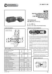
DSE3JSERIES 2010 - OVERALL AND MOUNTING DIMENSIONSDSE3J-A*DSE3J-C*DSE3J-Z*Adjustment sealing performed at factory.Do not disassemble the transducer.DSE3J-A* SADSE3J-C* SAdimensions in mm1 Mounting surface with sealing rings:4 OR type 2037 (9.25 x 1.78) - 90 shore2 Coil removal space (solenoid B only)3 Main connectionAdjustment sealing performed at factory.Do not disassemble the transducer.4 Electrical connector 7 pin DIN 43563IP67 PG11 EX7S/L/10code 3890000003(to be ordered separately)Fastening bolts: 4 bolts M5x30 - ISO 4762Torque: 5 Nm83 230/112 ED9/10
DSE3JSERIES 2011 - SUBPLATES (see catalogue 51 000)PMMD-AI3G rear portsPMMD-AL3G side portsPorts dimensions: P, T, A, B: 3/8” BSPDUPLOMATIC OLEODINAMICA S.p.A.20015 PARABIAGO (MI) • Via M. Re Depaolini 24Tel. +39 0331.895.111Fax +39 0331.895.339www.duplomatic.com • e-mail: sales.exp@duplomatic.com83 230/112 ED REPRODUCTION IS FORBIDDEN. THE COMPANY RESERVES THE RIGHT TO APPLY ANY MODIFICATIONS.10/10