531r control unit - FAAC
531r control unit - FAAC
531r control unit - FAAC

Create successful ePaper yourself
Turn your PDF publications into a flip-book with our unique Google optimized e-Paper software.
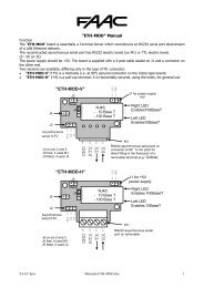
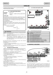
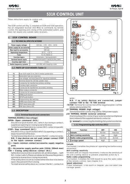
531R CONTROL UNITThese instructions apply to <strong>control</strong> <strong>unit</strong>:531RThe 531R <strong>control</strong> <strong>unit</strong> (Fig. 1), installed on 531R and 531K operators,has an integrated receiver (433 MHz) to command, by remote<strong>control</strong>, the opening and closing of the automated system, anddoes not require any outside radio receivers.1. 531R CONTROL BOARD1.1. TECHNICAL SPECIFICATIONSPowersupply voltage230 Vac. (+6% -10%) - 50 HzJ1J10LD1LD2LD3F2P ower supply for accessories24 Vdc.M ax load for accessories200 mA.Operating temperature-20 °C+ 55 ° CF usesF1, F2, (Table 1)FunctionlogicsAutomatic / SemiautomaticDS1J8Terminalboard inputsOPEN/STOP/SAFETY DEVICES/FAIL-SAFEC ourtesy light timer2 min.Radio frequency systems1.2. PARTS OF 531R BOARD (Table 1)433 HMz with hopping codeP1P2F1F 1 Fuse 5x20 rapid 10 A./250 V. (motor protection)F 2 Restorable fuse (accessories)J1J3J4J5J7J8J10P1P2DS1LD1LD2LD3Low voltage terminal board for inputs/accessoriesTerminal board for 230 Vac power inputConnector for transformer primary windingCourtesy light connectorConnector for transformer secondary windingMotor output connectorConnector for external antennaOPEN push-buttonSET-UP push-buttonProgramming dip-switchesOPEN input status LEDSTOP input status LEDFSW input status LED1.3. DESCRIPTION1.3.1. Terminal boards and connectorsTERMINAL BOARD J1 (low voltage)OPEN= Open command (N.O.)Any device (push-button, etc.) which, by closing a contact,supplies an opening (or closing) pulse to the door.To install several Open devices, connect N.O. contacts in parallel.STOP= Stop command (N.C.)Any device (e.g. a push-button) which, by opening a contact,stops movement of the door.To install several stop devices, connect the N.C. contacts in series.N.B.: if stop devices are not used, jumper connect STOPto the inputs common contact.= Inputs common contact/accessories supply negativepole.= Accessories supply positive pole (24Vdc 200mA max)FSW = Closing safety-devices contact (N.C.)Safety devices are all devices (photocells, sensitive edges,…) withN.C. contact, which, if there is an obstacle in the area they protect,operate to reverse door closing movement.If the safety devices are activated when the door is locked oropen, they prevent it from closing.To install several safety devices, connect the N.C. contacts inJ3J4J7J5Fig. 1series.N.B.: if no safety devices are connected, jumperconnect FSW to the -TX FSW terminal-TX FSW= Terminal for connection of the negative pole (-) of thephotocells transmitter (TX).J3 TERMINAL BOARD (high voltage)Terminal board for connecting 230Vac 50Hz power supply.J10 TERMINAL BOARD (external antenna)A terminal board for connecting an external antenna (Optionalitem) instead of the supplied standard conductor.terminal for connecting the shielding of any external antenna.No.1 Failsafe1.3.2. Programming dip-switches (DS1)Function2 Anti-crushing sensitivity3 Radio codes programming4 Carriage speedOFFActiveLowInactiveHighONInactiveHighActiveLowFailsafeIf activated, it enables the photocell operating test before everymovement.Anti-crushing sensitivityFor doors with an irregular movement, it reduces the sensitivity ofthe anti-crushing device to prevent unwanted action by it.Radio codes programmingIf activated, it enables the 531R board to save the radio codesof the remote <strong>control</strong>s. (see chapter 4.1).Speed adjustmentIf door movement is too quick or irregular, you can select lowcarriage speed.3
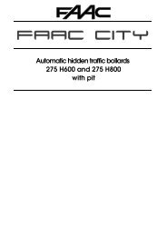
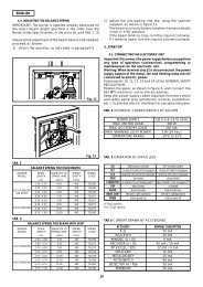
Meaning of status LEDLD1OPEN Input statusLD2STOP input statusLD3 FSW input status1.3.3. Input status LEDsLightOFFInactiveActiveSafety devicestripped2. FLASHING LIGHT AND PRE-FLASHINGA flashing light cannot be connected to this operator.3. CONNECTIONS OF SAFETY DEVICESNo changes to the connection of the safety devices. Refer tothe main instructions of the 531 EM operator.4. RADIO CODES PROGRAMMINGLightedActiveInactiveSafety devices disabledThe status with the automated system stopped and at rest isindicated in bold for every input.1) Turn switch No.3 of the DS1 programming dip-switches to ONposition.2) Press and hold down the SET-UP push-button , and then pressthe OPEN push-button for at least 1 sec.3) Release both push-buttons.4) The board deletes all the radio codes in its memory andautomatically returns to programming status.5) Proceed as from point 1 of chapter 4.1, or turn switch No. 3 ofthe DS1 programming push-buttons to OFF position, to endthe procedure.5. REMOTE CONTROLS T4 LC 433 MHZ.For remote <strong>control</strong> of the 531R operator, use the T4 LC remote<strong>control</strong>s only.Remote <strong>control</strong> T4 LC 433 MHz.4.1. PROGRAMMING RADIO CODES FROM THE BOARDThe 531R <strong>control</strong> board can save up to 10 radio codes. If otherremote-<strong>control</strong>s (T4 LC) are installed over this limit, the radio codesinput first are over-written.Programming procedure:1) To learn the remote-<strong>control</strong>s, turn switch No.3 of the DS1programming dip-switches to ON position (Fig.1).2) The courtesy light begins to flash rapidly and the boardremains in learning status.3) Press, for at least 1 second, the key of the selected remote<strong>control</strong>.4) When the courtesy light lights up for 2 sec on a steady beam,this signals that the transmitted radio code was correctly learnt.5) To save the code of other remote-<strong>control</strong>s, repeat theoperations from point 3.6) When learning has finished, turn switch No.3 of the DS1programming dip-switches to OFF position, and check if thecourtesy light has gone off.P4P26. GENERAL INSTRUCTIONSP1P3Fig. 24.2. PROGRAMMING RADIO CODES FROM THE REMOTE-CONTROLAttention: This programming procedure can be activated onlywith remote-<strong>control</strong>s already known to the 531R board. (seeparagraph 4.1)Programming procedure:1) Press push-buttons P1 and P2 of the remote-<strong>control</strong> (Fig.2)and always hold them down.2) The courtesy light lights up on a steady beam3) The courtesy light goes off after 5 secs.4) Release the P1 and P2 push-buttons of the remote-<strong>control</strong>.5) Within ten seconds after the courtesy light went off, press forat least 1 second the push-button of the remote-<strong>control</strong> youhad programmed, and which was therefore recognised bythe 531R board.6) The courtesy light will start to flash rapidly and the 531R boardwill go into learning status for 10 sec. Another radio code mustbe taught within this time:press, for at least 1 second, the keyof the selected remote-<strong>control</strong>.7) The transmission of a radio code will restart the 10 sec count,during which the board is in programming status.8) When the 10 seconds have elapsed, the courtesy light goesoff.Restart from point 1.For anything not expressly specified in these instructions, consultthe instructions of the 531 EM operator.EC DECLARATION OF CONFORMITYManufacturer : <strong>FAAC</strong> S.p.A.Address: Via Benini, 1 - 40069 Zola Predosa BOLOGNA - ITALYDeclares that: 531R <strong>control</strong> board,• conforms to the essential safety requirements of thefollowing directives:73/23/EEC and subsequent amendment 93/68/EEC.89/336/EEC and subsequent amendment 92/31/EECand 93/68/EECAdditional note:This product underwent tests in a typical uniformconfiguration(all products manufactured by <strong>FAAC</strong> S.p.A.).Bologna, 01 January 2005.The Managing DirectorA. Bassi4.3. DELETING RADIO CODESAttention: with this procedure, all the radio codes in the memoryare deleted.732869 Rev. A4