Untitled
Untitled
Untitled

Create successful ePaper yourself
Turn your PDF publications into a flip-book with our unique Google optimized e-Paper software.
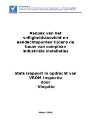
Group VINÇOTTEHead office : Business Class Kantorenpark Jan Olieslagerslaan 35 1800 Vilvoorde BelgiumTel +32 (0)2 674 57 11 Fax +32 (0)2 674 59 60 pressure@vincotte.be www.vincotte.comSafety surveillance approachduring the construction ofcomplex industrialinstallationsStatus report on behalf ofVROM InspectoratebyVinçotteMarch 2009
Introduction : Problem Statement0.0. Introduction: Problem StatementEnergy supply in Europe is mainly dependent on natural gas. This natural gas istransported in gaseous condition via pipelines or in liquid condition in specially equippedships and then stored in LNG terminals. These terminals are buffers in case that, becauseof conflicts (for example, the recent gas conflict between Russia and Ukraine), the gassupplying is interrupted. Belgium has a lot of experience in storing liquid natural gas. Thefirst gas terminal in Zeebrugge dates from 1984, and recently there have also been anumber of important expansions.Our company has actively, and in a number of domains, assisted in these projects asexpert, as External Service for Technical Control (EDTC), notified body and AuthorizedInspection Organization, with the mission of surveying the many aspects of constructingthis gas terminal.In the Netherlands, gas terminals are also being built. The construction on the Gateterminal has started in 2007 and it is hoped that the terminal is operational by 2011. It isself-evident that in the Netherlands sufficient surveillance cannot be disposed with. TheVROM-Inspectorate, in cooperation with the other surveying bodies, investigates for thisreason how the surveillance during the construction of LNG-terminals in the Netherlandshas to be organised. In this investigation, attention needs to be devoted to the questionto what degree quality certificates of equipment, materials, and activities are to be testedfor correctness.In this context, we were contacted by inspection services of the VROM to write a reporton the surveillance technique that has proven its usefulness in, among other projects,the extension project of the LNG-terminal of Fluxys in Zeebrugge. The question of VROMInspection concerns in the first place the safety aspects that have to be checked duringthe construction of such complex installations. Other aspects such as environment,company security and worker health are treated where there is a relation to safety. Ourexperience with controlling the construction of this type of installations teaches us thatthe problems encountered are of an identical nature, independent of the specificity andapplication area of the installations, which means that the extent of this study goes muchfurther than just solely LNG Terminals.In mutual agreement, the following topics were withheld:The legal requirements for building complex installations, such as LNG-Terminals, andthe inspection systems.The most important topics relevant for the integrity and safety of the installations:risk analysis, design of pressure-bearing parts, materials for pressure-bearing parts,construction and non-destructive testing of pressure-bearing parts, electricalinstallations, structures (concrete and metal), coating and isolation, control circuitsand safety control circuits.A description of the approach and inspection philosophy in the context of the firstextension of the LNG Terminal in Zeebrugge.The points meriting attention that we have established during our surveillanceactivities such as: the (international) systematics of inspection certificates and theexplanation of ‘weaknesses’ in said systematics, the role and limitations of ISO 9001certified quality systems in such projects, etc.A start for a focused inspection plan, which could be a starting document for possibleinspections to be executed.To treat this very broad domain, we called upon the age-old expertise of our employees.For the subjects enumerated for this purpose, we asked our experts to mention, inaddition to the theoretical background, the most important points meriting attention,based on our practical experience. You will find the names of the experts, whoparticipated actively on this report, in the preface. The finished texts were proofread byReport VROM-Inspectorate0.1© Vinçotte
Introduction : Problem Statementour two coordinators, edited and grouped in a number of chapters. We will know give ashort survey of these chapters.After an introductory paragraph which sketches the general context of Europeanlegislation, Chapter 1 looks at the main directives that apply when building complexindustrial installations. The Machinery Directive, the Pressure Equipment Directive (PED),the Atex-Directive, and the Seveso-Directive are discussed in sequence. In addition tothe European (economical) directives, there are also social directives that make demandsin addition to the minimal requirements. That is why both the actual Belgian legislationand the Dutch legislation are discussed.Chapter 2 takes a closer look at a number of technical aspects, and directs attention aswell to a number of shortcomings in surveillance and regulation. The following topics arediscussed in this order: risk analysis, design, materials, construction and inspection ofpressure-bearing parts, concrete and metal structures and their coating, electricalinstallations, control and safety control circuits and, finally, fire safety.The inspection philosophy our company used for the extension of the LNG terminal inZeebrugge is discussed in-depth in Chapter 3.Finally, we have collected all the points meriting attention related to surveillance inChapter 4 and have also made a start with a proposal for an inspection plan.In all this, it needs to be kept in mind that only topics were addressed for which ourcompany possessed sufficient experience and knowledge. Additionally, we certainly donot claim completeness for the topics discussed, partially because of the fact that thisstudy had to be conducted within a limited time and with a limited budget.Report VROM-Inspectorate0.2© Vinçotte
Legal Restrictions Pertaining to the Construction of (Complex) Industrial InstallationsCHAPTER 1 : LEGAL RESTRICTIONS PERTAINING TO THE CONSTRUCTION OF(COMPLEX) INDUSTRIAL INSTALLATIONS1.0. Contextualization of the European Legislation1.0.0 IntroductionThe purpose of this introductory part is to clarify the background and the purposeof the European legislative acts underpinning the current regulations related tothe safety of workers and of industrial installations. Other important issues suchas the protection of the consumer or the protection of the environment are notdealt withThis preliminary step is important because two different types of regulatory actsdo have a direct impact on the everyday life. A lot of time can be saved byreducing the misunderstandings about the purpose and the interfaces of thesemandatory requirements.Basically, we will identify two families of regulatory acts (European regulatoryacts are directives, decisions and regulations: the nature and the importance ofthese documents is described in Appendix 1)1.0.1 The regulatory acts related to the free movement of goods.The regulatory acts based on article 95 of the Treaty (previously article 100A).The idea is that "the Council shall […] adopt the measures for the approximationof the provisions laid down by law, regulation or administrative action in MemberStates which have as their object the establishment and functioning of theinternal market". Since the basic Idea is to promote the free movement of goods,these directives are sometimes called "economic directives" (DG Enterprises atCommission level). But most of these directives are also aimed at promoting thehealth and safety of European workers and consumers.Member States are responsible for ensuring the health and safety on theirterritory of persons, in particular of workers and consumers and, whereappropriate, of domestic animals and goods, notably in relation to the risksarising out of the use of machinery.Whereas 3 of directive 2006/42/EC of the European Parliament and of the Councilof 17 May 2006 on machinery, and amending Directive 95/16/EC (recast).The vast majority of the published documents are based on the principles of the"New Approach". Since there are still several operational questions on someissues, we will illustrate the background and the recent evolutions1.0.2 The regulatory acts related to the protection of the workers atworkThese regulatory acts are based on article 137 of the Treaty (previously article118A). This is a result of the Single European Act (1987). It was the first timehealth and safety at work had been dealt with in operational provisions of the ECTreaty. The idea is i.e. that the Community shall support and complement theactivities of the Member States in the field of "improvement in particular of theworking environment to protect workers health and safety". For these reasonsthe related set of directives is sometimes called "social directives" (DGEmployment and Social Affairs at Commission level). One should nevertheless notReport VROM-InspectorateI.1© Vinçotte
Legal Restrictions Pertaining to the Construction of (Complex) Industrial Installationsforget that there is also an economical dimension: one of the purposes is to limitthe possibilities of Member States to make social dumping.Whereas health and safety are, without doubt, key ingredients in employmentquality, represent one of the Union's most important social policy areas andcomprise a major economic dimension.Council resolution of 3 June 2002 on a new Community strategy on health andsafety at work.Regulatory acts adopted under article 95 and Article 137 are complementary.Directives under article 95 are mainly intended to ensure the placing on themarket of safe products and under article 137 they are intended to ensure thehealthy and safe use of the products at the workplace.Most of the directives are developed within the scope of the framework directive89/391/EEC 1 as amended by 2007/30/EC 2 . From now we want to indicate theeffects of the "Better regulation" as illustrated by directive 2007/30/EC. Theissue is quite simple: the Member States have to report on the practicalimplementation of 17 particular directives referring to the framework directive.For historical reasons, the provisions on reporting are sometimes inconsistent interms of both frequency and content. This situation is pure waste of time andmoney for the Member States and in addition to that it makes exploitation of theresults much more difficult at Commission level. It might be seen as a detail butin the regulatory world as in our individual lives, the devil is often in the details.We will elaborate further on this issue in the section dealing with the RegulatoryImpact Analysis.1.0.3 The “New Approach”: a revolutionary measure requested by theIndustry in order to promote the free circulation of goodsa) The Evolution of the European Doctrine for Harmonizing LegalDemands on ProductsThe very recent publication of the Package on Internal Market for goods (August2008) is the culmination of a process where lessons were taken from the past inorder to improve the regulatory tools. As will be seen the main issues are relatedto the improvement of the efficiency of the system as well as the clarification ofthe role and duties of the different operators, including the public authorities.The basics of the different steps will be highlighted hereafter. The trends of theevolution are illustrated in figure 1.0.1.Basically, it goes about a mutual learning process. Every regulation (or lack ofregulation) introduces specific incentives for the economic operators. Sometimes,the foreseen effects do not happen. In the beginning of the eighties, when the"New Approach" was designed, one of the fears was an excess of marketsurveillance at national level. There were a lot of reasons to expect it, hiddenprotectionism was not the less significant. Actually this did not happen and thenew idea is that market surveillance should not be "tolerated" but ""mandatory".In the same context of surveillance of the market, another important issue is the1 Council directive of 12 June 1989 on the introduction of measures to encourage improvements inthe safety and health of workers at work – OJ L183, 29.06.19892 Directive 2007/30/EC of the European Parliament and of the Council of 20 June 2007 amendingCouncil Directive 89/391/EEC, its individual Directives and Council Directives 83/477/EEC,91/383/EEC, 92/29/EEC and 94/33/EC with a view to simplifying and rationalising the reports onpractical implementation – OJ L165, 27.06.2007Report VROM-InspectorateI.2© Vinçotte
Legal Restrictions Pertaining to the Construction of (Complex) Industrial Installationsclear definition of the role and duties of the economic operators. The concepts of"putting into service" or "putting on the market" was not legally defined. Thedefinitions of the importer and the identification of its duties are inconsistentbetween the directives. As a result, it is possible for an operator to say to theauthorities that he fully agrees with the fact that the product X is dangerous butthat he cannot be held as responsible because the product was not yet sold (puton the market) and/or because the manufacturer is somewhere in the world andthat it is up to the authorities to try to get in touch with him and to tell him thathe is accountable.The many contacts with the different operators have taught us that it is of thehighest importance to know “why one does something” (does one have to do it?)before one can know “how to do it”.The structure of Europe has its very own logic. This logic is often different fromthe logic that underlies our national customs. A first step is thus to gain insight inthe general framework, and integrate the European doctrine in our thoughtpattern.One of the main objects of this paragraph is therefore to stress the understandingof the exact extent of new regulative concepts introduced into the EuropeanUnion. The implications of the CE-marking, the use of harmonized standards, therole (and responsibility) of the Commission, the role (and responsibility) of theMember States, the role of accreditation, … these are all themes that have to bemastered.2008Package onInternal Marketfor Goods2005BetterRegulation1989GlobalApproach1985New Approach1969Harmonisationof technicalregulationsFREE CIRCULATION OF GOODS THE IMPORTANT STEPS IN THEDEFINITION OF THE DOCTRINESimplify existingregulationRegulatory ImpactAssesmentTotalharmonizationPolitical definitionof the fundamentalrequirementsRules defined atEuropean levelNational andEuropeanRegulatorsConformityAssessmentStandards EN45000 SeriesHarmonisedstandards asregulatory tool(technical)Mandate givenby theCommissionStandardisationBodiesSpecific duties ofthe notifiedbodies(operational)Demonstrationof competenceAccreditationPreferred wayConformityAssessmentBodiesSpecific duties ofthe economicoperatorsManufacturersImportersDistributorsDemonstrationof competenceand impartialityAccreditationbodiesDuty ofsurveillance ofthe marketDesignation ofnotified bodiesNationalAuthoritiesFigure 1.0.1The problem is that people often have the annoying tendency of onlyremembering information that they like to hear. We have seen several involvedparties (including member states) defend with nail and tooth strategies that werein fact disadvantageous to them. When one considers then that these partiesoften turn to the wrong person, then what happens in the best case is aconsiderable waste of money and time. The European industry, however, cannotlet opportunities pass by anymore.Report VROM-InspectorateI.3© Vinçotte
Legal Restrictions Pertaining to the Construction of (Complex) Industrial InstallationsIn thus mess or “creative disorganisation”, it is of the utmost importance to haveat one’s disposition whole networks of informal contacts that allow the transfer ofideas on all levels of the hierarchy and influence the development of compromisesreached by the Member States 3 .To give an acceptable answer to the questions every one of us will ask ourselves,it is important to create a guideline, to familiarize ourselves with a doctrine ofwhich all elements can be replaced in their context. One of the best means toachieve this, is undoubtedly knowing how this doctrine has been conceived. It isour intention to capture in a few words the success and the setbacks that havemade the European (Economic) Community to create the communal legislationwe are dealing with right now, even if we do not know it yet.b) By Removing Technical Limitations Create an Instability that CreatesOpportunitiesProgram developed by the European Community for the build-up of the internalmarket was certainly the most ambitious economic change planned in peacetime.In fact, it was to be superseded later on by the opening of Eastern Europe in1989/90.In fact, Europe was out of options. The famous Cecchini-report, that waspublished in 1988, is not named “The Advantages of Europe” but “The Costs ofNon-Europe”.“We have to take our chances as they present themselves”, opportunists declare.“We have to create the chances to succeed”, strategists say.The opportunists are wrong.c) A European Doctrine Built in Five StepsH. DaemsAs we have seen above, for the moment Europe is formed on the basis of adoctrine that has strongly evolved since the signing of the Treaty in 1957. Fivesteps can be distinguished. The first three correspond to a Council Resolution.The fourth is a general philosophy (better regulation). The last and veryimportant step (August 2008) is based on a European regulation 4 and a Europeandecision 5 .Every one of these steps is a step ahead: always lessons are drawn from thepractical problems revealed during a previous step. Behind the technical terms wesee a thorough redistribution of responsibility and of regulatory obligations. Afterdescribing each step we draft an operational balance: roles of the differentplayers, advantages and disadvantages of the existing structure.We draw the reader’s attention to an important point. The redistribution of roleshas a considerable influence on the behaviour of the different economic3 Ch. D DE FOULOY - "Guide pratique des lobbyistes européens" - European study service – 1994.4 REGULATION (EC) No 765/2008 OF THE EUROPEAN PARLIAMENT AND OF THE COUNCILof 9 July 2008 setting out the requirements for accreditation and market surveillance relating to themarketing of products and repealing Regulation (EEC) No 339/935 DECISION No 768/2008/EC OF THE EUROPEAN PARLIAMENT AND OF THE COUNCILof 9 July 2008 on a common framework for the marketing of products, and repealing Council Decision93/465/EECReport VROM-InspectorateI.4© Vinçotte
Legal Restrictions Pertaining to the Construction of (Complex) Industrial Installationsoperators, whether they are the industry or the government or the accreditationinstitutions.Starting Point: National Standards and RegulationsThe Treaty of Rome gave an impulse to the internal market within the Communityby removing the two most constraining types of barriers of those days: customs’rights and the import quota. Since then, a number of very founded concerns,such as health protection, have pushed the Member States to impose a number oftechnical requirements, that each constitute a technical limitation of free trade.The community mechanisms dating from 1957 soon proved to be incapable ofhandling with this evolution.Usually, three kinds of technical limitations are distinguished:• The first come into existence by the differences that exist betweennational industrial standards (NBN, NEN, DIN, BSI, …), for whichcompliance has an influence on the import, sale, or use of a product. Thelimitations that these standards can impose on free trade can be verysubtle. Thus, it can happen that an insurance company only agrees to paydamages caused by construction materials if those materials were certifiedin accordance with a national standard.• Other limitations are created by the differences between nationalregulations. Here the limitations are not subtle at all anymore, regulationshave the force of law.• A third kind of limitations is caused by the testing and certificationprocedures that guarantee conformity of a product with national rules orindustrial rules. Free trade is limited every time the importing countryrequires a certification in addition to the one given in the country of origin;from this follow extra costs and slowdowns, that are well-known in asector such a pharmaceutical products.Since originally provided community mechanisms have not lessened or preventedthose technical limitations, there have to be some good reasons why theselimitations happen. In fact, there are three kinds of reasons:• Differences relating to the means that have to be applied to protect publichealth, safety, or the environment. One could speak here of “cultural”differences that are very normal between, for example, Scandinaviancountries and the Mediterranean. The implications of those differences arenot negligible, especially because they can touch the fundamental valuesof individuals. And individuals are often prepared to devote a greatamount of energy to defend their fundamental values.A classical example in this area is the judgement of the amount of trustone can put into an operator of a machine to ensure one’s own safety.That degree of trust can vary depending on the average education leveland the appraisal of human behaviour. Consequently, some countriesopine that the safety of machines can be partially ensured by calling uponthe responsibility of employees, whereas others will demand that securityis ensured in a constructive way by an intrinsic safeguard against anycarelessness, no matter how big. Thus, two different views on man lead totwo different views on machines. For free circulation of goods, however, itis exactly the point that every machine is considered safe in every cornerof Europe. Therefore, a compromise will have to be found.Report VROM-InspectorateI.5© Vinçotte
Legal Restrictions Pertaining to the Construction of (Complex) Industrial Installations• Different traditions of standardisation, testing, and certification. We allknow the great force of deep-rooted habits. The force of habit can causeeconomic operators to behave defensively towards products that complywith criteria they do not know. It has become clear, by the way, thatdifferences between national standards are a reflection of a differentdegree or a different rate of industrialization.• But also, often hidden beneath the reasons mentioned above, there is thewill to protect the interests of the national manufacturers, or even a wholeindustrial sector that is considered of strategic importance, despite theEuropean treaties.The Players• The national competent authorities (Ministry branch): establishes theregulations, monitors its correct application, provides the interpretation forthe texts.• Recognised bodies: appointed by local authorities to fulfil certain technicaltasks related to inspection and/or testing.In case of standardization, the structure is very similar: there is a national organ(NBN in Belgium) that delegates certain certification tasks to sector-boundorgans.EvaluationWe are dealing with co-existent, independent regulating systems. Thedisadvantages are well-known, the candidate-executor has to go through adifficult process and present his product for approval to demands that are notnecessarily reconcilable. In practice, this can cause costs for filing, costs fortranslation, for tests, for alteration of products, for supplies because of thenecessity of different “national” versions of the same model …Yet the decision structure is simple if we do not consider the marginal cases ofdirect lobbying at political institutions. That structure can be found in theschematic below. (Figure 1.0.2)COMPETENT AUTHORITYMANUFACTURERRECOGNISED BODYUSERFigure 1.0.2In such a system the manufacturer, should he have questions, can directlycontact the responsible authorities, that are often fully qualified to make adecision. That decision may be pleasing or not, but there is little legal insecurity ifthe manufacturer abides by it.Report VROM-InspectorateI.6© Vinçotte
Legal Restrictions Pertaining to the Construction of (Complex) Industrial InstallationsFirst Step of the Harmonization: the Extrapolation of National Systems1969 : harmonization of technical regulationBasic IdeaThe Member States have a technical regulation. Creating a harmonized Europeanregulation will solve the problems “other than tariff barriers”. The idea is that thevalidity of attestations and certificates of compliance given by the responsibleauthorities, given only under their responsibility and name, are recognized.The Players• Competent authority (Ministry branch): issues the certificates (andwithdraws them), maintains contacts with the other Member States. Isresponsible for the proper interpretation of the texts.• Technical service: the laboratory that issues the testing report upon whichthe certificate of the Ministry is based. Very promptly, and also for obviouspractical reasons, this function was expanded to an inspection function:interpretation and follow-up of tests at the manufacturers.Later (1992), the function also included the auditing of quality controlsystems, designed to ensure the legal conformity of production.EvaluationThis first step of the harmonization is today called the “old approach”. It is theconversion on the community level of the system hitherto applied to nationallevels. We have to keep in mind that these directives have led to a first importantredistribution of roles.• Regulatory texts are drafted on a community level and no longer on thelevel of the Member State.• Since the 1970s, manufacturers can, where these directives exist, fulfil thebasic purpose of the free circulation of goods. No matter where he isestablished in the world, any constructor can certify his product in anycountry of the European Communities and that certificate is valid in allcountries belonging to said Communities.Some of the directives applied, for example those related to toxic substances,cosmetics, or additives for foodstuffs, are binding for everyone. Others, forexample in the automotive sector, were optional for the manufacturers, whocould choose to obey either national regulations or European directives. In thesecond case, all national governments were forced to accept the Europeancertificates presented by the constructor.This system works well, but has the major disadvantage that it is bulky, and thusvery slow.These days, this old approach remains to be applicable for an economic sector ofthe highest importance to the European industry: the car industry. Since 1992,principles were slightly altered by some adaptations inspired by the rules of thenew approach: mandatory and no longer optional application; Monitoring ofconformity of production, …Report VROM-InspectorateI.7© Vinçotte
Legal Restrictions Pertaining to the Construction of (Complex) Industrial InstallationsToday, we see another type of evolution. The automotive market is not Europeanbut worldwide and the applicable regulation becomes more and moreinternational (based on the Geneva Agreement (United Nations)). This is a basicrequest from the big industry: they do not want to sell at European level butworldwide. This can have positive results: due to scale effects, the higher level ofrequirement set on safety and environment can be brought without increase ofthe cost at consumer level.When I hear somebody sigh, "life is hard", I am always tempted to ask,"Compared to what ?"Second Step of the Harmonization: the New Approach1985 : harmonization of technical regulationsSidney Harris+ the use of standardsAlthough the Council Resolution dealing with a new approach is already morethan twenty years old, it proposes a coherent whole of changes of whicheconomic operators do not always perceive the practical consequences. This topicis important, and we go further into it in paragraph 1.0.4.Basic IdeasThe harmonization of the technical regulations lead to a very bulky and thus veryslow and expensive approach, with very detailed technical attachments.Furthermore, governments do not always have technical specialists at theirdisposal. The two aspects of the technical regulation are thus kept apart.• Political side reserved for regulation (the government): the objectiveswhich need to be achieved (for example necessity of a specific type ofprotection, safety coefficient, tolerable sound levels, …)• Technical aspect reserved for standardisation (private sector): means toachieve those targets. Actually, the New Approach is a limited form of coregulation,one of the tools proposed under the European "BetterRegulation" mantra.The legislative role is clearly defined: it goes about• Setting objectives• Ensuring compliance• Protecting the public interest• Guaranteeing accountability (this was not successful)There is no de legation of legal responsibilityReport VROM-InspectorateI.8© Vinçotte
Legal Restrictions Pertaining to the Construction of (Complex) Industrial InstallationsCAVEAT- Consultation is not a substitute for democracy- Institutional balance must be respected- Legislation must guarantee procedures- Representation must be transparent- Access to results must be guaranteed 6The operators involved• Competent authorities: are mainly responsible for appointing the notifiedbodies. Have to be kept informed of critical situations (withdrawal ofcertificates, refusal to issue a certificate, …)• Notified Body: is responsible for all operational aspects, from issuing acertificate of EC-type examination and dispatching certificates to the otherbodies. It can also be responsible for following-up production and/or “fullquality assurance” modules.• Standardization organizations: this period has been a golden age forEuropean standardization organizations (CEN and CENELEC) whoseactivities were merely confidential up to that time.EvaluationThe new approach has added several dimensions to the simple decision structurewe showed in Figure 1.0.2. The rise in the number of intervening parties hasnecessitated the creation of several coordination structures. These structures arefurthermore explicitly described in the texts of the new approach. The generalschematic can be presented as follows.6 Enterprise Seminar 11 February 2003 – The future of the New Approach : Quo Vadis ?- AnneWilkinson - BrusselsReport VROM-InspectorateI.9© Vinçotte
Legal Restrictions Pertaining to the Construction of (Complex) Industrial InstallationsCourt of Justice - StrasbourgCommissionMember StatesWorking GroupCoordination of notified bodiesStandardization bodies CEN/CENELEC/ETSIManufacturerNotified bodiesUserFigure 1.0.3From Figure 1.0.3, it becomes quickly clear that this structure can lead to agame of complex interaction between the different players. These interactions canbecome even more complex as a consequence of the interaction betweendifferent directives applicable to the same group of products.Another difficulty comes from the implicit need for a consensus, due to divergingpositions taken for historical reasons, it appears to be almost impossible to reacha common position on some critical questions.In a decision process, complex interactions often lead to contradictory points ofview. The manufacturer who wants to know what to do to have his productcomply with regulations, sometimes has difficulties seeing clearly through all this.In an age of information, we establish with regret that whoever wants to put aproduct on the market sometimes has difficulties to find a straight answer to aquestion such as “Where do I begin?”. However, different valuable source ofinformation exist. We will explore them further in the chapter on the “official”sources of information.Third Step of the Harmonization: the Global Approachharmonization of technical regulation+ use of standards+ validation of the conformity assessmentThe “Global Approach” supplements and expands the principles of the “Newapproach”.Report VROM-InspectorateI.10© Vinçotte
Legal Restrictions Pertaining to the Construction of (Complex) Industrial InstallationsBasic IdeasWith the new approach a doctrine is introduced to demonstrate the compliancewith regulatory requirements. That doctrine guarantees flexibility of the economicoperators. But guarantees remain to be given to the users. This implies that thecompetence of manufacturers and third parties can be ensured. As with technicalregulations, there are two different aspects.• Political aspect: the competent authorities notify the Commission (andthus the other Member States) which body they have chosen to fulfil aparticular task. The word “notification” was chosen because sounds moreofficial than the word “designation”. The authorities can only notify bodiesfor which it can demonstrate the competence. This element is treatedmore thoroughly later on.• Technical aspect: the competence of these bodies has to be assessed onthe basis of objective criteria and not on the aura of respectabilityconferred to them by the approval of public authorities.. Just as there areessential requirements for products, there are also essential requirementsfor notified bodies. These requirements are defined in the annex to the“new approach directives.. For a body complying to the EN ISO CEI 17000(before EN 45000) series is identical to a presumption of conformity to therequirements made in the annexes mentioned above. That condition isinsufficient, since the technical competence for the scope covered by therelevant directives also has to be shown.It was supposed that accreditation is an excellent means to displaycompetence. The Commission could not impose them in every MemberState (some “hesitate” very consciously) but strongly stresses theprinciple. In many cases, accreditation bodies simply do not have a cluehow they should handle the issue. And Europe cannot function withoutnotified bodies.The operators• Competent authorities: their role is very similar to what was describedabove. It needs to be pointed out, however, that they are obliged to bearresponsibility for the competence of the bodies they notify. Othereconomic or political operators can not only dispute the validity of thecertificates but also the competence of the bodies.• Notified body: its role and obligations are expanded upon.• Accreditation bodies : being the top level of conformity assessment in theMember States, the accreditation bodies are strongly empowered in orderto bring objective evidence of the competence of the conformityassessment bodies.Report VROM-InspectorateI.11© Vinçotte
Legal Restrictions Pertaining to the Construction of (Complex) Industrial InstallationsBetter Regulation : back to the basics – cutting the red tapeFigure 1.0.4 Cutting the red tapeWe will not elaborate too much on this general issue but it is important to knowsome of the background elements.In 2005, the Commission wanted to reinforce its political ownership as well as theoverall coherence of the strategic political EU agenda. The Commisions thenlaunched a "better regulation project" with the aims to improve the quality ofnew legislation, and update many existing rules to make them clearer. To thatend it is therefore:• Withdrawing a number of pending legislative proposals. In fact, asof March 2006, the Commission had withdrawn 67 legislative proposalsafter screening 183 potential new laws that were pending ratification bythe Council and European Parliament.• Implementing a strategy to simplify existing legislation• Tackling the issue of administrative burdens, attacking "red tape" at EUlevel (and stimulating such attacks at Member States level)• Placing greater emphasis on the use of impact assessments and publicconsultations when drafting new rules and regulations. The aim is toassess how new legal measures could help or hinder the function ofEurope’s enterprises.Basically, the issue is not deregulation but "smart regulation". To reduce theheight of the wall of the "acquis communautaire" is certainly a good thingprovided it is made according to transparent and proven methodology. One of thedifficulties is rased by statements made at the simplistic level of slogan-politicsand shallow journalism.Report VROM-InspectorateI.12© Vinçotte
Legal Restrictions Pertaining to the Construction of (Complex) Industrial InstallationsProposals must be prepared on the basis of an effective analysis of whether it isappropriate to intervene at EU level and whether regulatory intervention isneeded. If so, the analysis must also assess the potential economic, social andenvironmental impactWhite Paper on European Governance, 2001, COM (2001)428Impact Assessment is or should be a key element in this revamping process. Oneif the basic idea is to clearly define the problem to be solved and to carefullyanalyse the alternatives to a new regulation.There are three kinds of alternatives- Status quo or baseline option. It is, for instance, stated that "The option of‘no EU action’ should always be considered, except in cases where there is anobligation to act laid down by the Treaties" 7- Alternative incentives : regulations are nothing more than incentiveinstruments. Many incentives are possible. Are self-regulation or co-regulationfeasible options ? Could the same objective be met by securing a voluntaryagreement ? Is an information and education campaign sufficient ?- More efficient regulatory design : once basic incentives are selected, thedesign of regulation has enormous effect on the impact. The Commission hasinvested a lot of energy in the strealining or simplification of existingregulation (including codification of existing regulations).Common regulatory problems : a web of systemic governance issues√√Complexity and inconsistency- Policy fragmentation, lack of coordination- Confusion on the role of regulation in modern society- Poor regulatory implementation capacities- Inconsistent decisions and signals to the private sectorGood regulation can become bad regulation over time- Immortality of regulations- Technological change- Social needsScott Jacobs – "Smart regulation for markets : The vision of regulatoryreform" – Regulatory Impact Analysis Training Course – College of Europe,Brugge Campus – 10-14 March 20087 European Commission – Impact Assessment Guidelines – SEC(2005)791 – Edition 15 June 2005with March 2006 updateReport VROM-InspectorateI.13© Vinçotte
Legal Restrictions Pertaining to the Construction of (Complex) Industrial Installations1.0.4 The Internal Market Package for Goods : revamping the NewApproacha) The New Legislative Framework (NLF) : modernisation of the NewApproach for marketing of products - published in the OJEU on 13August 2008The set of Regulatory acts published in the OJEU of 13 August 2008 is the resultof four years of high level and intensive discussions between the Commission, thestakeholders, the European Parliament and the Council.Basically, there are four objectives- To consolidate the key concepts of the New Approach policy;- To improve the evaluation and monitoring of conformity assessment bodies(testing, certification and inspection laboratories) including the increased useof accreditation- To strengthen market surveillance- It is expected that the credibility of the CE marking will be enhancedThe references of the regulatory acts are as follows (Regulation 764/2008 is quitespecific and will not be discussed later in this text)- REGULATION (EC) No 765/2008 OF THE EUROPEAN PARLIAMENT AND OF THECOUNCIL of 9 July 2008 setting out the requirements for accreditation andmarket surveillance relating to the marketing of products and repealingRegulation (EEC) No 339/93- DECISION No 768/2008/EC OF THE EUROPEAN PARLIAMENT AND OF THECOUNCIL of 9 July 2008 on a common framework for the marketing ofproducts, and repealing Council Decision 93/465/EEC- REGULATION (EC) No 764/2008 OF THE EUROPEAN PARLIAMENT AND OF THECOUNCIL of 9 July 2008 laying down procedures relating to the application ofcertain national technical rules to products lawfully marketed in another MSand repealing Decision No 3052/95/ECb) The Regulation on marketing of products will be applicable as from 1January 2010- It is binding in its entirety and directly applicable in all Member States- It sets out the requirements for accreditation and market surveillance relatingto the marketing of products.One of the great challenges induced by the Regulation is the duty of surveillanceof the market by the Member States.- Member States shall identify the responsible authorities- Member States shall establish and make publicly available surveillanceprograms.- The Commission shall develop and maintain a general archiving and exchangeof information system.Report VROM-InspectorateI.14© Vinçotte
Legal Restrictions Pertaining to the Construction of (Complex) Industrial Installations- Control of products entering the Community market (includes repeal ofRegulation 339/93/EEC).- There is a black sheep in every flock. (Figure 1.0.5)Figure 1.0.5 Where’s the black sheep ?(acknowledgements to Edouard Cornelis)c) The Decision on a common framework for the marketing of productsis addressed to the European regulators.To be operational it needs to be fed into existing Directives when they arerevised. Two sectorial directives are currently under revision and will be alignedwith the decision (as much as possible)- The toys directive- The construction product directive (intended to become a regulation)The Decision is a tool for the Commission’s Better Regulation policy. The rationaleis to ensure more consistency of the legal environment and to establish acommon “culture” of legislating. The identified inconsistencies: (differentterminology, different logic behind obligations of economic operators, duplicationof procedures,..) make it difficult and more expensive for economic operators tocomply with the legal requirements. On the other hand it should be kept in mindthat European regulatory acts are well implemented and that the improvementsinduced by harmonisation can be out weighted by the (administrative) costinduced by the requested changes.1.0.5 The So-Called Social Directives – The Other Side of SafetyThe directives “free circulation of goods” are but one of the aspects of thegrowing Europe. The Single Act created new clear social responsibilities on aEuropean level.Article 153 (previously article 137 and previously article 118A) gives the Councilthe authority to adopt social directives. Apart from safety and health on theworkplace, those “social” directives mostly involve various aspects, from the freeReport VROM-InspectorateI.15© Vinçotte
Legal Restrictions Pertaining to the Construction of (Complex) Industrial Installationscirculation of workers to the equal treatment of men and women. Initially, thetendency was to put the focus on safety and health in a narrow sense. 8Without further details, we point to the importance of the executive directive thatis aimed at the promotion of the amelioration of safety and health of workers. 9That framework directive is followed by several individual directives, of which wehave already introduced some.Of particular interest here are the first three directives, with requirements forworkplaces, for the use of work equipment and for the personal protectiveequipments.A practical example can be found in the machine directive in which a number ofrequirements are set out for machines that are put on the market. The “social”directive on work equipment defines, among other things, the requirements thatapply to the existing equipment. Those requirements apply since January 1 st ,1997.That directive of 1989 was far from complete, and the Commission proposed anamendment that introduced a significant number of changes.For the technical side of things, we find an expansion of the minimumrequirements for specific work equipment such as woodworking machines,presses, mobile work equipment, lifting devices and – accessories, scaffolds, …Another change is in the obligation imposed on the employer to draft or haveanother party draft a plan for the control of work equipment, dependentupon the planned utilization and taking into account possible indications ofmanufacturers. That plan has to make it possible that the employer sufficientlycomplies with obligations defined in the directive.- Make sure that the means of labour, the safety of which is dependent uponinstallation conditions, are subject to a first inspection (after the installationand before the first utilization) and an inspection after every installation on adifferent location, to ensure that these work equipment have been correctlyinstalled and are working properly.- Make sure that the work equipment that can cause dangerous situations whendamaged are subject to regular and exceptional inspections (after exceptionalevents that might lead to dangerous situations).The practical impact of this obligation to draft a plan for the inspection of thework equipment is dependent upon its transposition to national law.One of the new missions that the recognised bodies in Belgium have developed isto help companies to put their machinery in order as determined in this directive.Even more than before, everything will be a matter of accountability. In this theemployer will see the added value.8 E. Vogel-Polsky en J. Vogel, "Het sociale Europa 1993: illusie, alibi of realiteit?", Uitgaven vande Universiteit van Brussel, 19919 Council Directive 89/391/EEC of 12 June 1989 on the introduction of measures to encourageimprovements in the safety and health of workers at work O.J.. nr 183, 29-06-89Report VROM-InspectorateI.16© Vinçotte
Legal Restrictions Pertaining to the Construction of (Complex) Industrial InstallationsThere are a great number of individual directives- Council Directive 89/654/EEC of 30 November 1989 concerning the minimum safety and healthrequirements for the workplace- Council Directive 89/655/EEC of 30 November 1989 concerning the minimum safety and healthrequirements for the use of work equipment by workers at work- Council Directive 89/656/EEC of 30 November 1989 concerning the minimum health and safetyrequirements for the use by workers of personal protective equipment at the workplace- Council Directive 90/269/EEC of 29 May 1990 concerning the minimum health and safetyrequirements for the manual handling of loads where there is a risk particularly of back injuryto workers- Council Directive 90/270/EEC of 29 May 1990 concerning the minimum safety and healthrequirements for work with display screen equipment- Council Directive 92/57/EEC of 24 June 1992 concerning the implementation of minimum safetyand temporary or mobile construction sites- Council Directive 92/58/EEC of 24 June 1992 concerning the minimum requirements for theprovision of safety and/or health signs at work- Council Directive 92/85/EEC of 19 October 1992 on the introduction of measures to encourageimprovements in the safety and health at work of pregnant workers and workers who haverecently given birth or are breastfeeding- Council Directive 92/91/EEC of 3 November 1992 concerning the minimum requirements forimproving the safety and health protection of workers in the mineral-extracting industriesthrough drilling- Council Directive 92/104/EEC of 3 December 1992 on the minimum requirements for improvingthe safety and health protection of workers in surface and underground mineral-extractingindustries- Council Directive 93/103/EC of 23 November 1993 concerning the minimum safety and healthrequirements for work on board fishing vessels- Council Directive 98/24/EC of 7 April 1998 concerning the protection of the health and safety ofworkers from the risks related to chemical agents at work- Directive 1999/92/EC of the European Parliament and of the Council of 16 December 1999 onminimum requirements for improving the safety and health protection of workers potentially atrisk from explosive atmospheres- Directive 2002/44/EC of the European Parliament and of the Council of 25 June 2002 on theminimum health and safety requirements regarding the exposure of workers to the risks arisingfrom physical agents (vibration)- Directive 2003/10/EC of the European Parliament and of the Council of 6 February 2003 on theminimum health and safety requirements regarding the exposure of workers to the risks arisingfrom physical agents (noise)- Directive 2004/40/EC of the European Parliament and of the Council of 29 April 2004 on theminimum health and safety requirements regarding the exposure of workers to the risks arisingfrom physical agents (electromagnetic fields)- Directive 2006/25/EC of the European Parliament and of the Council of 5 April 2006 on theminimum health and safety requirements regarding the exposure of workers to risks arising fromphysical agents (artificial optical radiation).Report VROM-InspectorateI.17© Vinçotte
Legal Restrictions Pertaining to the Construction of (Complex) Industrial Installations1.1. European Legislation1.1.1 The Pressure Equipment Directivea) The European Pressure Equipment Directive 97/23/ECThe “Pressure Equipment Directive”, henceforth called PED, is, together with the otherEuropean Directives, a part of the unification process of Europe.The PED is mandatory for vessels, pipes, steam generators, appendages, safetyappendages, and assemblies with a maximum operating pressure above 0.5 bargthat are put for the first time on the European market (one or more member states). Thedirective is mandatory since May 29, 2002.Despite many exceptions, more pressure equipment than ever before are subject to therequirements of this directiveThe most important exceptions are those subject to other European Directives or to othernational, regulations.The PED is an economic Directive, founded on Art. 100 of the Treaty of Rome, inopposition to the social directives founded on article 118 of the same Treaty ofRome.Economic Directives are addressed to manufacturers and applicable on products thatthese manufacturers put on the European market for the first time.Economic Directives introduce fundamental requirements of safety, health, andenvironment.Social Directives, on the other hand, are addressed to employers and owner/users ofinstallations and contain requirements concerning the safety and well-being of workers,such as the Directive for work equipment 89/655/EEG.In opposition to the economic directives, the social directives are not (yet) or notcompletely transferred to the national legislations of the different member states.This may give a strange feeling, as if “safety” is less important than economic interests.Economic Directives have the purpose of guaranteeing the free circulation of goodswithin the unified European market by eliminating all possible obstacles to this in theprocess. For example, when the Directive for pressure equipment was implemented, themember states were forced to withdraw their own national regulation related to pressureequipment, so that, among other results, all national legal and regulatory obstacles wereremoved in favour of the Directive.The Directive thus guarantees the free circulation of goods within the unified Europeanmarket, independent of the origin of the equipment, and as far as the requirements ofthe Directive are respected.The first concepts that were adopted during the unification of the regulation for pressureequipment, namely the fine-tuning of a European design and manufacturing standardwith very detailed technical contents, eventually led to nothing due to years of arguingback and forth, an argument not at all devoid of chauvinism, between the member statesof that time. Because each one of these member states wanted to see its own vision onsafety and attendant regulation transposed to a European level.These negative experiences, but also the rise of quality control and quality assurancetechniques and especially of the ISO 9000 and the EN 45000 standards, combined withan ever stronger drive for unification, generated a new concept, one that was called the“new and global approach”.Thus, the European Directive for pressure equipment is a “new approach” Directive,just like the Machinery Directive and the ATEX-Directive.New approach Directives have some very specific characteristics, of which the mostimportant one are its essential health and safety requirements. These are crucial safetyReport VROM- InspectorateI.18© Vinçotte
Legal Restrictions Pertaining to the Construction of (Complex) Industrial Installationsrequirements that mandatory have to be taken into account in the design andmanufacture of the pressure equipment insofar as the corresponding risk exist when theequipment is used in reasonable conditions as expected by its manufacturer. To clarifythis, it is important to know that the Directives of the new approach are not onlyconcerned by safety, but also by health and environmental aspects of individuals, andeven of pets or goods.The necessity for the manufacturer to care about “the reasonable conditions of use”immediately introduces a second specific characteristic, one inherent to the Directives ofthe new approach, namely the obligation to conduct a risk analysis to find out whichhazards exist on account of pressure.He should than take into account the result of his analysis in the design and manufactureof the equipment.Thus, these directives are regularly called “risk-related directives”.Conducting a risk analysis is not self-evident, certainly not for the classical equipmentmanufacturers who have never gotten used to it. Furthermore, a manufacturer does notalways have all necessary data basic design information, or transients etc. of theequipment at his disposal, and thus he will not always be able to cover all aspects.The essential requirements are structured like most design and construction codesand standards, and therefore start by stating generalities. Further on, aspects such asdesign, materials, fabrication, inspection and tests are treated in independentparagraphs. The essential requirements, however, do not give any technicalspecifications for the design or manufacture of a pressure equipment.They are expressed in very general terms that do not always facilitate theirunderstanding and application by manufacturers and other users.Thus, the Directive prescribes:- Pressure equipment must be designed in the correct manner, taking into account allrelevant factors to guarantee that the equipment is safe during its whole lifespan…This implies, among other things, that for every pressure device the lifespan has to bedetermined.And what could constitute a relevant factor here…?And moreover:- In case the hydrostatic pressure test is harmful or impossible, other tests with arecognized value can be carried out. For other tests than the hydrostatic pressuretest, additional measures such as non-destructive tests s or other equivalent methodshave to be taken before these tests are carried out.One could wonder on what basis the equivalent value of other tests will be assessed?And what are suitable methods of non-destructive tests?Is it possible to check the structural integrity of a pressure device without actuallyputting it under pressure?Furthermore:- The following prescriptions normally apply. But when they are not applied, such as inthe case of materials not referred to individually and no harmonized standards wereused, the manufacturer has to be able to show that fitting measures have been takento achieve an equivalent level of general safetyThe lack of more clarity and objective criteria leads to very different interpretations ofthis requirement!In the last example that should illustrate the lack of clarity in the essential requirements,the term harmonized standards was used.In the time period when the Directive was being drafted – something lasted some 15years – the idea also grew to create European standards, i.e. technical specifications andrequirements necessary for designing, manufacturing, inspecting and testing of pressureequipment, which should allow one to meet essential requirements as well. For thisReport VROM- InspectorateI.19© Vinçotte
Legal Restrictions Pertaining to the Construction of (Complex) Industrial Installationspurpose, the CEN (European Committee for Standardization) got a mandate from theEuropean Commission to prepare standards that should allow coverage of the wholerange of products of activities related to pressure equipment, taking into account theapplicable essential requirements.In this manner, a manufacturer using a harmonized standard, will automatically gain apresumption of conformity with the essential requirements.A European standard acquires the status “harmonized” when the standard passes the socalled“formal vote” and is published in the Official Journal of the European Union. Thedifferent member states are then supposed to give the standard a national status and atthe same time to withdraw possible national standards that could contradict the contentsof the harmonized standard.The story of the harmonized standards is not a complete success story.Drafting and approving the thousands of required standards consumed too much time,among other reasons because of the necessary consensus that had to be acquired fromthe different member states, each one with their own safety philosophy and chauvinism.It hardly needs to be said that some of those member states could exert a lot morelobbying influence than other, smaller, member states.Some member states, for example, opted for low safety margins (read: safetycoefficients) with a relatively high frequency and strictness of inspection and control,while other member states rather chose high safety coefficients, which then result in overdimensioning and for which a relatively low amount of inspections and controls isrequired.Furthermore, the use of harmonized standards is not mandatory.A manufacturer can use national and international standards at all times insofar as he isable to demonstrate that all applicable essential requirements are respected.Due to their non-compulsory nature, many companies maintain their old trustedstandards. On the one hand this is due to their year-long experience with thesestandards. Thus, for example, almost all petrochemical installations are designed andbuilt according to API, ASME, and/or ASTM standards and codes. On the other hand theprinciple “unknown is unloved” is at play here.A next characteristic of these Directives of the new approach and of the pressuredirective in particular is the division in risk categories.This division is based on, as we might suspect on the basis of the degree of danger orrisk, which in this case of course the pressure in the equipment. The directive is talkingabout PS the maximum allowable working pressure for which the equipment is designed.This can be the design pressure, but the design pressure can be higher than the maximaloperational pressure for a whole host of reasons, such as standardisation. The maximalworking pressure is mostly the set pressure of the overpressure safety device of theequipment or of the installation. Furthermore, the type of fluidum has to be taken intoaccount. Indeed, a distinction is made between gases, vapours, and fluids with a highvapour pressure on the one hand, and liquids on the other hand.For both categories, a further distinction is made between dangerous and non dangeroussubstances, using the classical categorization for dangerous substances (see also ECDirective 67/548) found in most national regulations, namely, substances that areexplosive, very lightly inflammable, light inflammable, inflammable (with a maximumallowable temperature higher than the flashing point), very toxic, toxic or oxidating.Furthermore, one additional parameter is taken into account, namely the potential storedenergy (under the form of pressure) in the equipment. Depending on the type ofequipment, this is expressed in volume (in liters) for all kinds of vessels, or in nominaldiameters (thus without dimension, but derived in millimeters) for pipes and all kinds ofappendages for which it is common to express these in diameters.Relative to these parameters, all types of pressure equipment are divided into riskcategories, from category I, the lowest, up to category IV, the highest.It needs to be remarked that for every configuration an area “Art. 3.3” is prescribed. Thespecification Art 3.3 of course refers to the paragraph from the Directive that explains it.Report VROM- InspectorateI.20© Vinçotte
Legal Restrictions Pertaining to the Construction of (Complex) Industrial InstallationsWhat is involved in the case of complex industrial installations are equipment for whichthe maximum working pressure certainly is more than 0.5 bars, but for which thecombination of a relatively low pressure with a relatively low volume (or small diameter)does not constitute a veritable risk. For these equipment, the essential requirementsshould not be applied, and thus these equipment may not bear the CE-marking.To illustrate this, one of the nine configurations is presented below in Figure 1.1.1.1.This refers to table 2 of annex II of the Directive. The table applies to vessels intended tocontain a non-hazardous gas (such as pressurized air, nitrogen, or steam).Figure 1.1.1.1After determining the risk category, we proceed to the next step, which constitutes another aspect of the Directives of the new approach, namely the choice of the procedureof assessment of compliance with the essential requirements.The Directive provides a number of assessment procedures in annex III from which themanufacturer can choose depending on the risk category, and by which he demonstratesthat he respects the applicable essential requirements.Thirteen assessment procedures are available (cf. Table 1.1.1.1) that can be used ontheir own or in combination with others.The impact of the risk category is thus limited to the degree of conservatism and thestrictness with which compliance with essential requirements is assessed.Indeed, most of the essential requirements are expressed in very general terms, andcontain few qualitative requirements. The need to apply higher “safety requirements” forhigher risk categories, mostly due to higher pressure and other loads, is actually takeninto consideration by the design and construction standards.The manufacturer can, within the possibilities provided within the limitations of thedirective, select the assessment procedure he wants to apply. His selection will bedetermined by, among other factors, whether or not he has a quality system in place,and also whether he plans a one-time or serial production.The table below sums up the relations between risk categories and assessmentprocedures that can be utilized. On its left side, procedures are represented based ontraditional inspection such as review and certification of design, review of other technicaldocuments, witnessing manufacture, inspection and testing activities.It is worth noting that no intervention of a recognized notified body is required incategory I.The intervention of a third party, called notified body, is also a characteristic of thesenew approach directives.Report VROM- InspectorateI.21© Vinçotte
Legal Restrictions Pertaining to the Construction of (Complex) Industrial InstallationsIn category II, this intervention is required but only in the construction phase and not inthe design phase, and only by sampling.For categories III and IV, the assessment of design and construction is required at alltime.The design review under the form of a pure and formal design approval under moduleB1, or under the form of a type examination under module B. In addition to the puredesign, a type investigation will also assess the physical realisation based on one or moreprototypes for aspects such as manufacture, inspection and testing activities.In some cases, the Directive allows to intervene by sampling, such as, for example,under the modules A1 and C1, in category II, respectively in category III, in conjunctionwith a type examination.Furthermore, it needs to be remarked that for the procedures based on a qualitysystem assessment, the different parts of the ISO 9000, 1994 edition, are referred to,not because this certification standard applies in its 1994 version, but to distinguishbetween the different requirements made by the directive and those dependent on therisk category, namely, a quality system that only covers final control and testing(modules E and E1) or a quality system that covers both fabrication and final control andtesting (modules D and D1), and then finally a complete quality system that also coversthe design activities (module H and H1).In the frame of procedure H1, the directive requires, and this despite the fact that acomplete quality system is implemented, that the notified body conducts a formal designreview and also devotes specific attention to the final control. The reference made to theISO 9000 standard is, as said before, not really binding. The Directive requires that thequality system in question has to demonstrate in a binding way that it meets theessential requirements. The ISO 9000 standard is but one of the possible means toachieve this.In principle, every assessment procedure or combinations of it should have the same“weight” within a certain risk category.By a mere comparison of the procedures with and without a quality system assessment(left and right side of the table, respectively), important differences result due to thecomplete difference in approach. It is not easy to compare and assess activities such asreviews, inspections or tests as to their conformity with a standard or specification, withthe assessment of the related quality system.The common introduction of quality systems for all kinds of reasons has in a way createda vacuum in the world of quality auditing.To check conformity with technical and other requirements via quality audits, onecertainly has to be familiar with the design and construction of pressure equipment, andin practice it shows that few auditors are competent and qualified for this. One can onlybe sure of equivalence between the two parties around the table if one has an efficientand effective appraisal of the quality system at one’s disposal.Within an identical table half, it is hard to speak of advantages and disadvantages. It allamounts to choosing the most flexible and economically justified choice for themanufacturer. An adequate choice of a type can, for example, have a considerablenumber of long-term advantages if the manufacturer has to deal with only minorvariations that feature unimportant deviations of the earlier approved design or type.Report VROM- InspectorateI.22© Vinçotte
Legal Restrictions Pertaining to the Construction of (Complex) Industrial InstallationsCATEGORY ICATEGORY IICATEGORY IIICATEGORY IVWithout quality assessmentWith qualityassessmentSerial One-off Serial One-offA1interne manufacture control with unexpectedchecks on the final controlB + C1EC-type examination+conformity with thetypeB + FEC-type examination+product inspectionB1 + FEC-designexamination+product inspectionGEC-unit verificationAinternal manufacture controlD1 of E1 (ISO 9002+ of ISO 9003+)production quality control or product quality controlB + E (ISO 9003+)EC-type examination +product quality controlB1 + D (ISO 9002+)EC-design examination +product quality controlB + D (ISO 9002+)EC-type examination+production quality controlH (ISO 9001+)complete quality assuranceH1 (ISO 9001+)complete quality assurancewith formal design approvaland sharpened supervision onfinal controlTable 1.1.1.1 Relations between Categories and Evaluation ProceduresA constant in all this is the compilation, by the manufacturer, of the technical design andconstruction file in which he gathers all elements that demonstrate that all applicableessential requirements have been satisfied.It is primarily the manufacturer who takes the responsibility of putting his devices inconformity with the Directive, to evaluate them and to finally declare conformity with theDirective, with or without the help and confirmation of a notified body.From different legal cases in the framework of this Directive it appears that theappropriate courts of law have the tendency to assert shared responsibility in the case ofthe intervention of a notified body, as far as the latter is judged to be in error.Therefore, it is important that the notified body take its responsibility, obviouslydependent on the selected assessment procedure, very seriously.This message is even more important when dealing with certain procedures (B1, B, Gand the design review under H1) where the notified body is asked to support a formalconformity with the Directive. We’d like remark here that the notified body is not adesigner, nor a pressure vessel manufacturer and that the means at its disposal toconduct its evaluation, are per definition (as a third party) rather limited.In the frame of other assessment procedures such as A1, C1, F, but also for otherprocedures founded on quality system assessment, the situation is less clear-cut. What isat stake here is more than merely formulating observation and objective self-evidences,and it needs to be remarked that the reports published not necessarily conclude formalconformity with the Directive, nor can they be seen as a certificate or attestation ofconformity.In what preceded, it was mentioned a couple of times that from category II onwards, athird party intervention, the notified body, is required for a number of configurations.The notified bodies are designated by one of the member states on the basis of minimalrequirements imposed by the directives and further by the individual appraisal of eachmember state.The notified body conducts a number of assessments, ranging from simply attending thefinal inspection by sampling, to the formal assessment and certification of the design andmanufacture of a category IV pressure equipment (module G) or the assessment of theconformity of a quality system with respect to the requirements of the Directive.Depending on the selected assessment procedure, the notified body delivers a report or acertificate.Report VROM- InspectorateI.23© Vinçotte
Legal Restrictions Pertaining to the Construction of (Complex) Industrial InstallationsFrom that moment onwards, the manufacturer is allowed to attach a nameplate with aCE marking to the equipment and also (obviously only from category II onward) theidentification number of the notified body that was involved in the manufacturephase.Both of these features constitute, together with the declaration of conformity drafted bythe manufacturer, a kind of passport for the free circulation of the pressure equipment onthe European market.The declaration of conformity is truly a very important element in this context because itimplies the formal responsibility of the manufacturer or of his representative residingwithin the European Community.Theoretically considered, it is not required to deliver the declaration of conformitytogether with the pressure equipment. The only requirement is that the manufacturerfiles this declaration for ten years after putting the product on the market, and keeps itat the disposition of the authorities whenever they may need it. Yet there does exist aguideline 9/16 explaining this and “recommending” the delivery of the declaration ofconformity. “Guidelines” are official interpretations and clarifications of the Directive.They are phrased and prepared by the forum of notified bodies on the requirement of allpossible users, and submitted for approval by the “Working Group Pressure” of theEuropean Commission. These guidelines are published on the official website of theCommission.(http://ec.europa.eu/enterprise/pressure_equipment/ped/directive/index_en.html).The recommendation to deliver the declaration of conformity together with theequipment anyway is not a major indulgence since the exploiter of the pressure devicehas to be able to show, in the context of the social Directive work equipment, that alleconomic Directives applicable to the “devices” were respected. As we will see further on,this is also necessary in the case of assemblies.The declaration of conformity gives some of the following information:- the identity of the manufacturer or his representative residing within the EuropeanCommunity;- the description of the pressure device or assembly;- the selected assessment procedure- the identity of the notified body or bodies:- the technical documentation (standards and codes) that were used to respect theessential requirements;- in case of a assemblies , the declaration of conformity has to mention every individualpressure equipment integrated in this assembly ; this is necessary to ensure thateach individual equipment was judged for its conformity with the directive by theirrespective manufacturers;- when applicable the references of design- or the type-examinations- when applicable the references of other European Directives that apply, provide veryimportant information for the end user;- the identity of the signer of the declaration of conformity.However, when introducing the product on the market, the manufacturer will have todeliver a user manual, which, as its name implies, explains to the user how theequipment is to be used in a save manner, but that also needs to mention all residualrisks that could occur during the expected usage of the equipment.For the sake of completeness, it is important to explore some further aspects, such as:- The Technical Construction FileThis is a file in which a manufacturer has to file all self-evident information thatdemonstrates that all applicable requirements for the equipment in question havebeen respected. This file, together with the declaration of conformity, is to be filedand kept at the disposition of the authorities for ten years after the device is put onthe market.A table of contents of such a technical file can be found in the Directive.Report VROM- InspectorateI.24© Vinçotte
Legal Restrictions Pertaining to the Construction of (Complex) Industrial Installations- Application of other economical DirectivesAn equipment (for example a mixer under pressure, powered by an electrical motor)can be subject to several European Directives (machine directive, low-voltagedirective, directive of electro-magnetical compatibility, the ATEX-Directive forequipment destined to function in potentially explosive zones, …).It is important to realize that a CE-marking on a device means that all applicabledirectives were complied with. In such cases it is thus also important that this isconfirmed by the declaration of conformity.- Market supervisionThe Directive obliges member states to organize a market supervision in such a waythat all actors and products on the market are surveyed. The supervision of freecirculation is included in this.- MaterialsFor pressure-bearing materials, the Directive provides two alternative procedures inthe cases where no European harmonized standards are utilized. These are assessingprocedures (European material approval and Separate Material Evaluation)specifically developed for checking conformity with the applicable essentialrequirements.- Final InspectionThe directive provides for a final inspection in all cases, by the manufacturer and thenotified body (from category II onwards), whether in a sampling manner or not.The essential requirements represent in a very detailed way which aspects have to bereviewed during that final inspection.- AssembliesThe directive also applies to assemblies (different pressure equipment assembled asan integrated and functional whole by the manufacturer).For the assessment, the Directive provides a special assessment procedure that,apart from the status of the individual equipment, is mostly concerned withcompatibility and interfaces, and also with the safety of the assembly against theexceeding of acceptable operating limits. Pressure is one possible applicableparameter, but also other parameters such as temperature, level, flow, etc. canapply.- Industrial InstallationThis term is used to distinguish an assembly assembled by the user from theassembly assembled by the manufacturer. In opposition to assemblies, industrialinstallations are not subject to the Directive but to national legislation.Something is called an industrial installation when the integration (assembling) ofdifferent individual pressure devices happens under the responsibility of the user onhis site.Reason: In opposition to the first part of guideline 3/1, which confirms that theDirective also applies to equipment manufactured by a user (for his/her own use), thesecond part of this guideline states that this is not the case for assemblies ofequipment, who are for this reason called industrial installations.- Numerical valuesIn the essential requirements, we can find some numerical values, such as thepressure to be applied for the hydrostatic pressure test, the minimum impact value of27 joules, safety coefficients to be applied in the calculations …Due to the regular usage of non-European harmonized standards, it happens thatthese values cannot be applied or respected right away.The “taking measures to achieve an equivalent safety level” as the Directiveprescribes, is not always a simple exercise.b) Shortcomings or Weaknesses of the SystemThe directive imposes legal obligations.It imposes obligations on the manufacturers and on the notified bodies.Report VROM- InspectorateI.25© Vinçotte
Legal Restrictions Pertaining to the Construction of (Complex) Industrial InstallationsIt also imposes obligations on the member states, such as the supervision of those actorsinvolved but also on the products.We are not qualified and have not enough information to judge the efficiency ofsupervision in Belgium and other member states.On the other hand, we are regularly confronted with administrative anomalies (contentsand form of declarations of conformity, contents and form of material certificates) butalso with technical shortcomings (not reaching the prescribed material characteristics,undetected deficiencies in material or welding joints …).These anomalies often have two main causes.On the one hand, there is the factor of competition since neither the unity prices nor theinspection or assessment programs are unambiguously set. Manufacturers of pressureequipment (such as all economic players in any market) are tempted to work with thecheapest “suppliers”.Also, by opening up the European market (also for notified bodies), the monopolyposition of some national bodies was broken.Another cause that can influence the cost of an intervention is for example the size andmeans of the inspection company.Bigger and more experienced inspection companies often have a staff of experts on nondestructiveanalysis, in metallurgy, possibly a laboratory, tools and human resources fordesign review and approval … It is self-evident that the possibility to call upon suchexperts, internal as well as external, also affects unity prices. Young, small inspectioncompanies with a relatively small staff and limited action radius do not have to deal withthese costs to the same degree.The total costs of an assessment by a notified body depends to an important extent tothe number and duration of the interventions.Not rarely are we confronted with a trimmed intervention program.Since the task is to observe and supervise, it is obvious that the effectiveness andefficiency of the interventions are directly influenced by their duration and frequency.In addition to the effects of competition, an insufficient nature of the interventionsobviously also has an important impact on the “quality” and thus on the guarantee thatthe equipment were designed and manufactured in conformity with the Directive.This insufficiency can then be further split up, on the one hand in insufficient competencyand experience of the inspectors and engineers conducting the assessments andinspections, and on the other hand in deficient quality systems (ISO 9001 or others).From our year-long experiences, not only with the pressure directive (since 2002) butalso in the nuclear sector, with the usage of section III of the ASME code (since 1975)wherein quality criteria are integrated in design- and construction requirements, we havenoticed that many users (both manufacturers and inspectors) have a lot of trouble withseamlessly integrating product quality criteria with system quality criteria. Regularly,fundamental quality parameters and thus also conformity parameters are treated poorly.All this results in non-conformities and all kinds of anomalies that can be divided intothree groups:- Incomplete, incorrect basic materials A conservative estimate, supported by objective evidences and research, is that30% of the 3.1 certificates (which number above 200) was issued erroneously,due to the fact that the products they are supposed to cover correspondincompletely or absolutely not to the criteria required. Fraud by material manufacturers and suppliers when certifying materials.An investigation by the Belgian welding institute involving the brittle breakingbehaviour of flanges in SA 105 materials established that 50 to 60% of theflanges acquired for testing corresponded incompletely or absolutely not with thecertificates that applied to them.Report VROM- InspectorateI.26© Vinçotte
Legal Restrictions Pertaining to the Construction of (Complex) Industrial Installations Incorrect execution of destructive testing (size testing bars, bending over a lessconservative calibre diameter, bending of 90° instead of 180°…). “Foul play” by inspection agencies with 3.2 certification.3.1 certificates are only countersigned and, if necessary, integrated in a documentwith the heading of the inspection agency itself.- Insufficient non-destructive analysis The quality certificates of the operators are no guarantee that the non destructivetesting technique/parameters are sufficient to detect the expecteddeficiencies/indications or flaws (especially when dealing with ultrasonic, eddycurrent, but also with radiographic and even magnetic and dye check testing). Aqualification or validation of the method would not be advisable here.The Directive does not require a formal approval of the non destructive testingprocedures by the notified body. On the other hand, many notified bodies do nothave sufficient competency to check or approve such procedures.- Non-conform design Use of erroneous allowable stresses or other design input data. Incoherent data. Use of configurations not accepted by the standard. Lack of as built conformity assessment. It is common that during manufacture of apressure equipment, there is a deviation from the design approved in advance, fordifferent reasons. Not rarely, such deviations can have an impact on the stresscalculations. Without a final comparison between the situation “as designed” andthe situation “as built”, this cannot be called an acceptable situation.As mentioned earlier, the quasi-exponential growth of ISO 9001 certification is not anundivided success. Not only due to the need of a large number of quality systemauditors, but also because a number of those auditors have to possess sufficientcompetency and experience, proper to the technological aspects of design andmanufacture of pressure equipment.In essence, the possibility that the Directive offers to adopt a quality system route whendemonstrating conformity really leads to a kind of auto-certification and thus leads to adecrease of the interventions of the notified body.It is frustrating to see that the majority of the manufacturers do not only lackunderstanding of the ISO standard, but are also incapable of putting down and applyingthe individual requirements of the PED in a quality system, while it is expected of thenotified body to drastically reduce its interventions and mainly focus on systemsupervision, rather than product supervision.A very specific deficiency, but one really generated by the Directive itself, are theassemblies of equipment that are compiled under the responsibility of the exploiter on hisown site and are therefore called industrial installations and are as such not subject to anassessment required by the Directive, due to the non-necessity of CE-marking andintervention of a notified body.The reasoning here is that in such cases there is no economical act being conducted.However, the first part of guideline 3/1 is clear. When an exploiter/user assembleshimself with different parts (heads, flanges, nozzles …), this equipment does require anassessment of conformity with the Directive. We have never understood the legislatorwhen he makes the distinction between assemblies and industrial installations, were itnot that thereby he provides the possibility of deviating from the Directive.Assessing assemblies, as is specifically required by Article 10 § 2 of the Directive, isindeed a logical step in checking the assembly for safety, as it applies for the individualequipment.Especially the third part of the global conformity assessment procedure and theassessment of the safety provisions is for most assemblies a burdensome task and wecannot grasp at all why users are trying to avoid third-party assessments here.Because if we look further in the tangle of European laws and Directives, we then seethat there does exist something like a social Directive (cf. the beginning of thisReport VROM- InspectorateI.27© Vinçotte
Legal Restrictions Pertaining to the Construction of (Complex) Industrial Installationsparagraph). For example, the Social Directive for work equipment requires that a usermakes sure that all applicable Directives have been respected for all work equipment heputs at the disposition of his workers, thus closing the circle in the end.Indeed, assemblies (or industrial installations) can be as dangerous as individualequipment, and furthermore we may think that it has never been the intention of theauthors of the Directive that assemblies were to be built that did not conform to thesafety requirements to which individual equipment are subjected.Report VROM- InspectorateI.28© Vinçotte
Legal Restrictions Pertaining to the Construction of (Complex) Industrial Installations1.1.2 The Machinery Directive and the Work Equipment Directivesa) Machinery Directive (98/37/EC)Scope:What is a machine in the framework of complex installations?To gain an insight in the application of the machinery directive and the directiveon work equipment, it is important to take a closer look at the scope of themachinery Directive.Art. 2. The Directive’s definition of:Machine:What is a machine according to the Directive?- an assembly of linked parts or components, at least one of which moves,with the appropriate actuators, control and power circuits, etc., joinedtogether for a specific application, in particular for the processing,treatment, moving or packaging of a material,- an assembly of machines which, in order to achieve the same end, arearranged and controlled so that they function as an integral whole,- interchangeable equipment modifying the function of a machine, which isplaced on the market for the purpose of being assembled with a machineor a series of different machines or with a tractor by the operator himselfin so far as this equipment is not a spare part or a tool;Safety component:What is a safety component according to the Directive?- a component, provided that it is not interchangeable equipment, which themanufacturer or his authorised representative established in theCommunity places on the market to fulfil a safety function when in useand the failure or malfunctioning of which endangers the safety or healthof exposed persons.Simple machines:The application of the Machinery Directive does not only depend on the definition,but also on:a) The mechanical risks present:- When the risks are for example mainly of electrical origin, only the lowvoltage directive applies (art. 1.5)- When no risks are present, in other words if none of the essentialrequirements apply, the directive will de facto not be applicable.Report VROM-InspectorateI.29© Vinçotte
Legal Restrictions Pertaining to the Construction of (Complex) Industrial Installationsb) the exceptions (relevant for complex installations):- machinery whose only power source is directly applied manual effort,unless it is a machine used for lifting or lowering loads;- steam and pressure vessels;Manual shutters, storage tanks and pipelines, for example, are covered by thisand are thus excluded from the Directive.Assembly of machines:The directive, according to the definition of a machine, also applies to anassembly of two or more machines, working together (cf. article 2 § a definition):This means that an assembly of machines must also comply with the essentialrequirements of the annex I of the machinery Directive.For sizable complex installations, it is not always simple to determine whether weare dealing with an assembly of machines or not.Even if we assume that installations are not machines in the sense of theDirective, it seems logical that this should not make any difference to therequirements for an overall assessment of safety. The only difference isadministrative, namely the question whether the installation needs an additionaldeclaration of conformity and whether a CE-marking is to be attached.In practice, a complex installation can be mostly subdivided in a number of“machines” that work independently (for example an air treatment installation:although the installation can be part of a larger whole, it can be considered standalonein most cases).In many (process) installations, there are a number of individual machinesaccording to the definition of the machinery Directive. Those machines areconnected by a process. The different machines in the process should therefore,to the extent that they can function independently, bear a CE-marking, and beaccompanied by the declaration of conformity by the manufacturer of themachine.The safety aspects of the process itself will normally be the topic of a risk analysis(for example a HAZOP) as required by the frame directive for safety at work(which applies to the user – cf. infra).The Safety Components:These are equivalent to machines and the directive should be applied to safetycomponents that are put separately on the market.Application Example of the Directive Machines:- PumpsA pump contains moving parts that imply mechanical risks. The directive usuallyapplies.- (gas) shutterA motorized shutter accords with the definition of machine. Should mechanicalrisks be present, the directive will apply.A manual shutter (for example for a bypass) is not in the scope of the directive.Report VROM-InspectorateI.30© Vinçotte
Legal Restrictions Pertaining to the Construction of (Complex) Industrial Installations- Pressure controllerThe amount of moving parts is limited here. The mechanical risks are thus limitedas well. We are of the opinion that the directive is not applicable if the risks arelimited.- CompressorA compressor contains moving parts which imply mechanical risks. The directivenormally applies.- Assembly of machines (for example a gas decompression station, …):A combination of different machines should be considered as one machine insome cases. Cf. supra.Division in Risk-CategoriesThe Machinery Directive makes a distinction between machines that are includedin Annex 4 and machines that are not included in annex 4. Annex 4 covers 17types of machines, for which a specific procedure applies (cf. infra).The machines in annex 4 are mostly manually fed machines (with manualintervention of the operator) and a number of very specific cases involving specialrisks (for example hydraulic lifts for vehicles, lifting equipment for persons,household refuse collecting vehicles, etc.).For a complex installation, annex 4 will never apply.Conformity ProceduresThe machinery Directive contains two conformity procedures for machines,namely the procedure for machines in annex 4, and the procedure for the othermachines.For the machines of annex 4, an intervention of a notified body is mandatory insome form (EC-type examination, forwarded construction file, …).Due to the fact that complex installations are not referred to in annex 4, we limitourselves here to the procedure for non-annex 4 machines.The procedure for the non-annex 4 machines is the following:- Step 1: the machine must be built in conformity with the essentialrequirements of annex 1- Step 2: the proof of this conformity must be written down in a technicalconstruction file by the manufacturer (annex 5)- Step 3: The conformity must be declared by the manufacturer in thedeclaration of conformity (annex 2A)- Step 4: The conformity must be shown through the CE-marking (annex 3).Step 1: Conformity with the Essential RequirementsEvery machine must be in compliance with the essential requirements ofannex 1 of the directive.To establish which essential requirements apply, the manufacturer mustconduct a risk analysis on his machine.The importance of standards:Report VROM-InspectorateI.31© Vinçotte
Legal Restrictions Pertaining to the Construction of (Complex) Industrial InstallationsIn order to comply with the essential requirements, the Europeanharmonized standards should be followed. If these standards are followed,they provide a legal presumption of conformity with the aspects (essentialrequirements) that are covered by the standard.Although application of the European harmonized standards is notmandatory, it is important for manufacturers of machines to take theminto account.The standards are divided into three types:- type A are general applicable standards (for example EN 12100 generaldesign principles, EN ISO 14122 risk assessment, …)- type B are standards for common aspects (B1) (for example EN 60204:electrical equipment of machines) and safety components (B2) (forexample EN ISO 13850 emergency stop: principles for design)- type C are standards on the level of the machines themselves (forexample EN 1114-1 extrusion machines) or families of machines (forexample EN 692: mechanical presses).A list with the European harmonized standards is available on the websiteof the European Commission (www.newapproach.org).Step 2: the Construction FileBefore a machine can be placed on the market, or put into service, themanufacturer must compile a technical file according to annex 5 § 3a. Thisfile must contain the following elements:a) A Technical Construction File:a technical construction file comprising:— an overall drawing of the machinery together with drawings of thecontrol circuits,— full detailed drawings, accompanied by any calculation notes, testresults, etc., required to check the conformity of the machinery with theessential health and safety requirements,— a list of:— the essential requirements of this Directive,— standards, and— other technical specifications, which were used when the machinerywas designed,— a description of methods adopted to eliminate hazards presented bythe machinery,— if he so desires, any technical report or certificate obtained from acompetent body or laboratory (1),— if he declares conformity with a harmonized standard which providestherefore, any technical report giving the results of tests carried out athis choice either by himself or by a competent body or laboratory (1),— a copy of the instructions for the machinery;b) for series manufacture, the internal measures that will beimplemented to ensure that the machinery remains in conformity withthe provisions of the Directive.Report VROM-InspectorateI.32© Vinçotte
Legal Restrictions Pertaining to the Construction of (Complex) Industrial InstallationsThe file can be considered as the proof of compliance of the machineaccording to the manufacturer (and under the his responsibility).The file must kept available for the authorities (who can request it if thereis a sound reason for it) at the manufacturer for a period of ten years(after the last produced machine of a certain type). As such, the file is notdelivered with the machine.Step 3: The Declaration of ConformityThe Directive machines distinguishes between three types of declarations:- annex 2a: declaration of conformity- annex 2b: declaration of the manufacturer for machines intended to bebuild in or to be assembled with other machines- annex 2c: declaration of conformity for safety components.The declaration of conformity (annex II point a)For all machinery that is placed on the market or put into service, themanufacturer must deliver a declaration of conformity. This declarationis a legal document that engages the responsibility of themanufacturer.The declaration of conformity contains the following elements:- name and address of the manufacturer- description of the machine- all relevant provisions complied with by the machinery (so not onlythe machinery Directive, but other applicable directives as well,such as the low voltage directive, the pressure equipment directive,…)- identification of the person empowered to sign on behalf of themanufacturer or his authorized representatives.The declaration of the manufacturer (annex 2 point b):For machines meant to be built in or assembled with other machines,and which cannot operate independently, a declaration of themanufacturer according to annex II § b of the Directive machines isrequired.It is important to note that these declarations do not provide anyguarantee on conformity, but only contain a warning that the machinemay not be put into service before the conformity of the whole hasbeen established by the final manufacturer (this can also be theuser/exploiter).Such a declaration of the manufacturer can thus in no case beconsidered as the final declaration. Therefore, it is always necessary,that a declaration of conformity, according to annex II § a of theMachinery Directive, is drawn up by the ‘final’ manufacturer.The final manufacturer has in these cases an interest in obtaining thenecessary guarantees by contract from his supplier(s). Theseguarantees include, for example, conformity with the essentialrequirements that can be applied, the existence of a construction filethat proves the above, and instructions for a safe building-in orassembly (it should be noted here that the new machinery DirectiveReport VROM-InspectorateI.33© Vinçotte
Legal Restrictions Pertaining to the Construction of (Complex) Industrial Installations2006/42/EC (applicable as from 29/12/2009) will make theserequirements mandatory for the suppliers of machines meant to bebuilt in or assembled with other machinery (the so called ‘partlycompleted machinery’).In practice, such II b declarations are very common.Although not included in the directive, combined declarations (annexes2a and 2b) are also very common. In such a case, the manufacturerdeclares conformity with the Directive, and mentions the interdiction ofputting into service as well. This is often a paradox as the machine caneither be used independently or assembled as a part of an installation.In the latter case the essential requirements are dependent on thecorrect assembly and this should require conformity of the ‘whole’installation.The declaration of conformity for safety components (annex 2 point c):Same as for annex 2 a but without the CE-marking.b) The framework Directive and the Directive on Work equipmentThese directives are considering the users (employer/employee) and aim toprevent accidents at work.The framework Directive (89/392/EEC):Includes a general obligation to conduct a risk analysis and the taking of propermeasures, taking account of state of the art technology and techniques.The Directive on the use of Work equipment (98/655/EEC amended):In general: work equipment is defined as follows:'work equipment': any machine, apparatus, tool or installation used at work.What are the obligations of the user in this context:Art. 3 (Acquiring new work equipment: selection)The employer shall take the measures necessary to ensure that the workequipment made available to workers in the undertaking and/or establishment issuitable for the work to be carried out or properly adapted for that purpose andmay be used by workers without impairment to their safety or health.In selecting the work equipment which he proposes to use, the employer shallpay attention to the specific working conditions and characteristics and to thehazards which exist in the undertaking and/or establishment, in particular at theworkplace, for the safety and health of the workers, and/or any additionalhazards posed by the use of work equipment in question.Where it is not possible fully so to ensure that work equipment can be used byworkers without risk to their safety or health, the employer shall take appropriatemeasures to minimize the risks.Report VROM-InspectorateI.34© Vinçotte
Legal Restrictions Pertaining to the Construction of (Complex) Industrial InstallationsThe general principle is that, to ensure health and safety for his employees,the employer ensures that the work equipment he puts at his employees’disposal is suited to perform the intended work or is sufficiently adapted to dothis,- taking into account the labour circumstances and the foreseeable risks- if not, the employer should take appropriate measuresThis principle applies to all work equipment, not only to technical equipmentsuch as machines.Art. 4: Rules concerning work equipmentWithout prejudice to Article 3, the employer must obtain and/or use:(a) work equipment which, if provided to workers in the undertaking and/orestablishment for the first time after 31 December 1992, complies with:- the provisions of any relevant Community directive which is applicable;- the minimum requirements laid down in the Annex, to the extent that no otherCommunity directive is applicable or is so only partially;Here the connection is made with the ‘economic’ directives. The user, too, hasan obligation to choose work equipment that has a CE-marking, as far as itapplies. If no directives are applicable (or if none exist), the user will have toguarantee conformity with the work equipment directive.If we apply this principle to a complex installation on which the machineryDirective is not applied as an assembly, the user must take into account thatin this case the obligation of applying annex 1 of the work equipment directivebecomes his own responsibility.Depending on the situation, this obligation can be contractually transferred tothe manufacturer, but the responsibility cannot be transferred-that will remainwith the owner. This will for example be a possibility in a project with a singleprime contractor (turnkey construction contract). In the case of a projectwhere the user makes individual purchases of discrete machines orcomponents, this may not be possible.Report VROM-InspectorateI.35© Vinçotte
Legal Restrictions Pertaining to the Construction of (Complex) Industrial Installations1.1.3 The ATEX-Directivea) IntroductionIn what follows, the ATEX-Directives are succinctly presented. ATEX is anacronym derived from the French “ATmosphere EXplosible”. When we use theterm ATEX, we are referring to two European directives dealing with explosionprotection.In addition to a directive (ATEX 95 directive, 94/9/EC) that describes theconformity of materials, there is also a directive (ATEX 137, 1999/92/EC) thatincludes the obligation to assess the explosion risks by performing a risk analysis,and to control said risks by drawing up an explosion protection document.The ATEX-Directives describe on the one hand the technical requirements forequipment that is used in a potentially explosive atmosphere, i.e. an atmospherethat can become explosive because of local or operating conditions. On the otherhand, they describe requirements to exploit the workplace in the safest waypossible.As to ATEX, and more particularly explosion protection, we will focus on theapproach of process safety. This implies that we utilize the same methodology aswe use to analyse risks…Important in all this is that this risk analysis becomes integrated in the generalprocess safety study, in order to conform to the requirements of the directive.This only makes sense, however, if we are working in a process environment oranother complex environment regarding processes or substances. For processinstallations, the ATEX-Directive plays on the overlap between individual safetyon the one hand, and process safety on the other.ATmosphere EXplosibleAn explosive atmosphere is defined in the ATEX-Directive as “a mixture with air,under atmospheric conditions, of flammable substances in the form of gases,vapours, mists or dusts in which, after ignition has occurred, combustion spreadsto the entire unburned mixture”.b) Gas or Dust ExplosionA gas, vapour, or dust explosion is a sudden ignition, combined with a pressurebuild-up caused by the ignition speed and the volume in which the explosiontakes place. For this type of explosion, two things are required. The right air-fuelproportion and an ignition.If the sudden ignition does not take place in a confined space, a fireball or jet firemay appear.Explosions are roughly divided into gas explosions and dust explosions. Dustexplosions are not treated any further in this context.When gas or vapour is released, it mixes with air and will eventually dilute to asuch degree that the explosion danger disappears. Obviously this can only occurwhen a good (natural) ventilation is present. Only where the proper gas/airproportion (LEL) exists, there is a possibility of explosion in the case of ignition.Report VROM-InspectorateI.36© Vinçotte
Legal Restrictions Pertaining to the Construction of (Complex) Industrial Installationsc) The Economic Part (ATEX 95 Directive, 94/9/EC) and the Social Part(ATEX 137, 1999/92/EC)The ATEX-Directive is a European directive. The European Union expects of eachmember state that they transpose this European directive into nationalregulations. The ATEX-Directive is intended to achieve a total harmonization ofEuropean standards for the use of all equipment and safety systems in anexplosion-hazardous area.As already mentioned above, the ATEX-Directive consists of two directives. Thefirst one describes minimum safety requirements for equipment and protectivesystems intended for use in potentially explosive atmospheres (ATEX 95,94/9/EC) while the second describes requirements to ensure the safety of theworker in the best way possible (ATEX 137, 1999/92/EC). The directive containsminimum requirements for improving the safety and health protection of workerspotentially at risk from explosive atmospheres.Division of EquipmentThe directive divides the equipment and protective systems, which involves morethan just electrical material, into groups and categories with different protectionlevels.Category 1: includes equipment and protective systems that have to ensure therequired safety level, even in case of an exceptional equipment failure.Category 2: includes equipment and protective systems that have to ensure therequired safety level, even when dealing with frequent failures or predictable andaccountable deficiencies in the operation of the device.Category 3: includes equipment and protective systems that ensure the requiredsafety level when operating normally.Classification into zonesAn important element of the ATEX-Directive is the composition of a risk inventory,which leads to the classification of areas where hazardous explosive atmospheresmay occur into zones. Within these zones, ATEX 95-approved equipment must beapplied.These areas can be divided into the following zones:Zone 0: A place in which an explosive atmosphere consisting of a mixture withair of flammable substances in the form of gas, vapour or mist is presentcontinuously or for long periods or frequently.Zone 1: A place in which an explosive atmosphere consisting of a mixture withair or flammable substances in the form of gas, vapour or mist is likely to occur innormal operation occasionally.Zone 2: A place in which an explosive atmosphere consisting of a mixture withair of flammable substances in the form of gas, vapour or mist is not likely tooccur in normal operation but, if it does occur, will persist for a short period only.The classification into zones takes no account of the consequences but is solelybased on the probability of an explosive atmosphere occurring. The directivedemands the prevention of the formation of explosive atmospheres; and if this isimpossible ignition should be avoided; if the nature of the activity does not allowthis, the detrimental effects of an explosion have to be mitigated so as to ensurethe health and safety of workers.Report VROM-InspectorateI.37© Vinçotte
Legal Restrictions Pertaining to the Construction of (Complex) Industrial InstallationsThe idea behind zoning is the estimation of the likelihood that explosiveatmospheres occur. After an estimation of the probability, ignition sources shouldbe avoided so that the probability of an explosion becomes acceptable.Classification into zones does not take consequences into account. Whenclassifying into zones, it is important that the product properties are known andthat danger sources are taken into account (for example where gas can bereleased).The ATEX 137 directive also applies to machines, via the explosion protectiondocument.c) Explosion Protection DocumentAccording to the directive, the employer is obliged to draw up and maintain anexplosion protection document.This document needs to contain at least the following information:• Identification and evaluation of explosion risks• Classification of workplaces into zones• Description of installations, processes, and/or activities• Description of used materials/safety parameters• Measures for protecting against explosion hazards• Organizational measures, safety instruction of workers• Marking of the explosion-hazard areas• The name of the individual responsible for the drawing up andmaintenance of the document.d) Interaction with Other DirectivesATEX and the EMC-DirectiveIn principle, a product has to conform to all applicable directives. Thus, in case ofthe ATEX-Directive and EMC-directive (Electro Magnetic Compatibility,89/336/EEC), both directives have to be conformed to. An example: anacceptable EMC-emission for equipment that emits electromagnetic waves cancause an explosion danger. In that case, ATEX takes priority.ATEX and the Low Tension DirectiveProducts to be used in a potentially explosive atmosphere are explicitly excludedfrom the low voltage directive (73/23/EEC). All low voltage requirements have tobe covered by the ATEX-Directive. Parts intended for use outside of thepotentially explosive atmosphere, but that contributes to the safe functioning ofequipment and safety systems, have to meet both the ATEX and low voltagerequirements.ATEX and the Machinery DirectiveThe relation between ATEX and the machinery directive (89/392/EEC) is different.The ATEX-Directive is a specific directive in the sense of the machinery directiveand contains very specific and detailed requirements to prevent any risk causedby a potentially explosive atmosphere. The machine directive only contains ageneral determination of the explosion risk. For the risks caused by a potentiallyexplosive atmosphere, the ATEX-Directive takes priority and must be appliedsupplementary.Report VROM-InspectorateI.38© Vinçotte
Legal Restrictions Pertaining to the Construction of (Complex) Industrial Installations1.1.4 The Seveso-Directivea) IntroductionThe expression “major accidents” refers to the “Directive 96/82/EC of thecouncil of December 9, 1996, on the control of major-accident hazards involvingdangerous substances”, also called Seveso II directive.The Seveso II directive is a review of the so-called Seveso I directive: the“Council directive of 24 June 1982 on the major-accident hazards of certainindustrial activities 82/501/EEC”.Where the Seveso I directive departed from a given industrial activity, theapplication area of the Seveso II directive is based on the nature and quantity ofthe dangerous substances present in an establishment, whatever its activity maybe.The Accident in Seveso in 1976The name of the Seveso-Directive stems from the city of Seveso in NorthernItaly, where an accident occurred in the pharmaceutical manufacturing plant ofthe Swiss group Hoffman-Laroche.The plant produced trichlorophenol. In a chemical reactor, the reaction becameuncontrollable, pressure and temperature built up and tetrachlorodibenzo-paradioxin(TCDD) got dispersed in the atmosphere via a safety valve. This accidentcaused no direct deaths. 400 to 500 people outside the factory, however, wereexposed to the then little known toxic dioxin, and there were many victimsamong cattle and pets. Large amounts of soil, polluted with dioxins, had to becarried off. This soil, stored in vessels, got lost, which led to a Directive on thesupervision and control within the European Community of the transfrontiershipment of hazardous waste (84/631/EEC).An important characteristic of this accident that eventually led to the directive isthe fact that neither the company, nor the police or the fire department wereactually aware of the dangers of the product that got dispersed. It was only afterseveral days that dioxin was discovered on discoloured leaves. Only afterwards,evacuation of the population commenced.The directive therefore came into being as a consequence of ignorance, anxiety,insecurity, and fear of the employer and his employees, as well as of the generalpublic and the government.Several other accidents are also at the basis of this directive, namely theexplosion followed by fire in Flixborough, England, in 1974.The main conclusions of the investigations of these accidents were that thepotential dangers associated with industrial activities were underestimated andthat legislation was no longer adapted. Because of the rising complexity, increasein scale, and the high technological level of the industrial activities, thegovernment realized that it was hard to elaborate a detailed legislation that wasapplicable at any given time. It was decided that legislation had to attempt toachieve a self-regulation of the industry. The dangers had to be controlled by theindustry and everybody had to be informed of what could happen and what theproper response should be.Report VROM-InspectorateI.39© Vinçotte
Legal Restrictions Pertaining to the Construction of (Complex) Industrial Installationsb) PurposeThe purpose of the directive is the prevention of major accidents in whichdangerous substances are involved, and the limitation of the consequences ofthis for man and environment. Thus, a high level of protection of the wholecommunity can be guaranteed in a coherent and effective way.This goal is aimed for both for the protection of employees, the population andthe environment. The directive only concerns major accidents.In the Seveso II directive, the stress is no longer on the risk of major accidents,but on controlling the hazards here of. Furthermore, no distinction is madeanymore between different industrial activities, but “major accidents” are onlydependent on the presence or the potential presence of dangerous substances. Itdoes not matter whether production, storage or laboratory activities are involved.The Seveso II directive has come into force in Flanders in the environmentallicenses policy (Vlarem I, Chapter IV) in 1999, and federally, in 2000, by meansof the Seveso “Cooperation Agreement” (Samenwerkingsakkoord in Dutch,hereafter abbreviated to SWA).On 31/12/2003, the Official Journal of the European Union published the directive2003/105/EC that amends the Seveso II directive. (first amendment of theSeveso II directive) This amendment of the Seveso II directive was transposedvia an adaptation of the Cooperation agreement (2006) that came into force on06/05/2007.c) Implementation and Amendation of the Seveso-DirectiveBelow, a short overview is given of the most important changes introduced by thefirst amendment:• Lowering the threshold values for the category “dangerous for theenvironment”• Separate addition rule for substances that are dangerous for theenvironment (no longer in combination with the (very) toxic substances)• Adaptation of the definition of an explosive substance• Addition of the definitions of gas and liquid• Extension of the list of carcinogenic substances• Adding potassium nitrate to the list of the named substances• Classification of ammonium nitrate in the list of named substances• Classification and clarification of “Gasoline and other oil fractions” and thelowering of threshold values• Processing activities and the related storage of dangerous substancesrelated to exploitation of minerals are also within the area of application ofthe directived) Legislation in the Netherlands vs. FlandersEnvironmental LegislationIn Flanders, the Department of Environment, Nature, and Energy is responsiblefor environmental legislation related to the Seveso II directive. In theNetherlands, the VROM (the ministry of Public Housing, Spatial Planning enEnvironmental Management) is responsible for this. The VROM has the followingpriorities: creating a pleasant living environment, conducting a spatialdevelopment policy and development of a durable future.Report VROM-InspectorateI.40© Vinçotte
Legal Restrictions Pertaining to the Construction of (Complex) Industrial InstallationsIn the Netherlands, the Environmental Management Act (Wet milieubeheer orWm) acts to protect the environment. This is the most important environmentallaw, which is based on the principle of “duty of care”. The EnvironmentalManagement Act gives general rules for various topics, from substances andwaste products to enforcement, right of access to environmental information,environmental licenses, and modalities of appeal. The Wm came into force onMarch 1 st , 1993. The Act is constantly amended by the VROM, with the purpose ofameliorating and reducing regulations. The Wm contains the generalrequirements for environmental management, while more specific requirementsare elaborated in decisions.The Activities Decree (Activiteitenbesluit)(in effect from 01/01/08) is a decisionincluded in the Wm, which imposes general requirements on companies. Thesecompanies do not need an environmental license (anymore). The decisionreduces administrative load for the industry. Companies are divided in threetypes (A, B, or C) of which only companies of type C have the obligation of havingan environmental license. More and more companies fall under the general rulesand do not need an environmental license (anymore). In the future, onlycompanies that fall under the European Council Directive of 24 September 1996concerning integrated pollution prevention and control (IPPC Directive 96/61/EC),will need an environmental license.Safety LegislationIn the Netherlands, the Decree Major Accidents (Risks) 1999 (BRZO 1999) andthe Hazards of Major Accidents Regulation are transpositions of the Seveso IIdirective. All companies to which the BRZO 1999 applies have to do everythingnecessary to prevent and limit the consequences of major accidents. BZRO 1999applies to installations in which dangerous substances, according to the Wmlicense, can be present or can be created in certain quantities as a result ofrunaway reactions in an industrial chemical process.In Flanders, the Seveso II directive was transposed to the CooperationAgreement.Installations that fall under a BRZO 1999 have to have a Prevention Policy MajorAccidents (PBZO) and a Safety Management System (VBS) in any case.Information duty also applies. In addition, companies from the high risk category(VR-duty-bound) have to draft a safety report (veiligheidsrapport or VR), aninternal emergency plan, and an updated substance list. These duties are thesame in Flanders, except for some minor differences. In Flanders, a VR consists ofa SWA-VR and an OVR. An internal emergency plan is complusory in Flanders forall (low and high threshold) installations, which differs from the situation in theNetherlands. The Commission Prevention of Disasters by Dangerous Substances(CPR) has published a number of reports in which the methods for QRAcalculationshave been included. These reports have been integrated in thepublication series “Dangerous Substances” (PGS). The Flemish legislation refersto these publications and these methods have to be followed completely in somecases.When drafting a QRA to determine the external human risk, the “Manual RiskCalculations Bevi” is consistently referred to, which is the replacement of the nolonger used Purple Book.For some topics, Flanders refers to its own publications, such as the HandbookProbability Rates.Thus, it can be concluded that both Flanders and the Netherlands have the samegoal in mind, but that their practical ways of reaching it are slightly different.Report VROM-InspectorateI.41© Vinçotte
Legal Restrictions Pertaining to the Construction of (Complex) Industrial Installations1.2. National Legislation1.2.1 The Situation in Belgiuma) The Nuclear Legislation and the Ministerial Decree of Deviation V4087There exist two regulations that apply to equipment and installations classified asnuclear in Belgium: On the one hand the regulation dealing with the danger of ionising radiationfor the workers and population. On the other, the regulation dealing with the danger of losing structuralintegrity of pressure equipment for the workers and population.In the context of this overview, we will obviously limit ourselves to the secondpart.Due to the lack of any relevant legislation but also due to the lack of design andconstruction requirements, Belgium pleaded, at the moment that it was decidedto build nuclear power plants, for the adoption of the American regulation of theUSAEC (United States Atomic Energy Commission) and the USNRC (United StatesNuclear Regulatory Commission), such as § 50-55a of the 10 CFR 50 (Code ofFederal Regulation) and the Regulatory Guide 1.26. These prescribe sections IIIand VIII of the ‘ASME Boiler and Pressure Vessel’ code for nuclear ‘safety classes’A, B, C en D.In that period (1974), something like the ARAB (General Regulation for LabourProtection) did exist in Belgium, a regulation that, among other things, providedprescriptions for the design and construction of steam devices, but that certainlywas not sufficient for this new form of steam generation and power production.Legally, this was arranged by drawing up ministerial decrees that contained adeviation from ARAB in favour of the ASME code(s), something that was repeatedfor every new plant that was to be constructed.In addition to the aspect of supervision on new constructions, the aspectsupervision in exploiting and the periodical inspections, replacements, reparationsand alterations were regulated via the same deviations, this time in favour ofsection XI of the ASME code.After several evolutions of the Belgian national legislation for steam devices (theearlier ARAB), a new all-inclusive ministerial decree was drawn up and approvedin 1993 (M.D. V4087 of 11/6/1993) for the seven Belgian plants in service at themoment.In an appendix, this ministerial decree provides some practical modalities inrelation to the interfaces and division of responsibilities between the differentintervening supervising organisations: for the section protection against ionising radiation, a recognized body of class1 is responsible (something that has also been changed by now); for the protection against the loss of structural integrity of pressureequipment, an authorized organisation qualified for evaluating steam devicesis responsible.To make the use of American regulations and construction codes go smoothly in aBelgian context, a number of conversions were set down. Thus, a documentcalled “Transposition of the ASME III code to the Belgian context” and anotherone called “Transposition of the ASME XI code to the Belgian context” were drawnup.Report VROM-InspectorateI.42© Vinçotte
Legal Restrictions Pertaining to the Construction of (Complex) Industrial InstallationsIn both these documents, a number of administrative, organisational, registerialand technical conversions are described that render the application of the ASMEcodes possible.Thus, for example, the supervision by an AI (Authorized Inspector, member of anAuthorized Inspection Agency in ASME III) and by an AII (Authorized In-serviceInspector in ASME XI) has been replaced by the supervision of an inspector of theauthorized body for steam devices.The extent of the supervision of the third party was adjusted too. Thus, in theBelgian context the authorized body for steam devices will also conduct thequality audits of ‘manufacturers’, ‘installers’ and ‘engineer organisations’, insteadof ‘The ASME Society’ as in the American context.Other conversions are not discussed here.Due to the fact that the ministerial decree of deviation in favour of the ASMEcodes is a deviation of the Belgian steam legislation, what precedes obviouslyapplies to ‘steam devices’.For that reason, the amendment explicitly stated what is to be considered asteam device.In the context of the Belgian PWR-plants, these are the reactor vessel and theprimary loop with all devices and branch connections up until the second shutterorgan, and also the secondary side of the steam generators and the secondaryloop with all devices and branch connections up until the first shutter organ. Thiswhole is referred to as the ‘nuclear steam vessel’.Furthermore, there are some individual devices that in themselves, due to theirdesign and operating conditions, are also subject to Belgian regulation.Obviously such a PWR plant consists of a lot more than a nuclear steam vesseland some devices…Analogous to the ‘steam’ part, all other pressure-bearing devices, pipes andinstallations, subject to ASME III or ASME VIII code are subject to supervision bya Belgian authorized body, depending on their quality class (A, B, C, D or D+)(there are some variants to this, but these are irrelevant to the currentdiscussion).The authorized organisation mainly intervenes in the following stages to checkthe structural integrity of the equipment and installations:Design ReviewEvaluation of QA-programs of ‘engineer organizations’Review of technical specifications;Review of design drawings and calculations;Review of execution drawings and execution procedures;Drawing up of inspection programs;Supply of Materials, Accessories and EquipmentEvaluation of QA-programs of manufacturers;Review of manufacturing and control programs and of fabrication procedures(forming, heat treatment …);Review of destructive and non-destructive testing procedures;Identification of the materials and review of the corresponding materialcertificates;Supervision and evaluation of qualification tests of welding procedures andwelders and of non-destructive testing procedure and personnel;Supervision of the execution of destructive tests and evaluation of results;Supervision of and evaluation of manufacturing activities;Report VROM-InspectorateI.43© Vinçotte
Legal Restrictions Pertaining to the Construction of (Complex) Industrial InstallationsSupervision of the execution of non-destructive testing and evaluation of theresults;Supervision of the strength and tightness tests;Visual and dimensional examination;Review of technical documentation;Marking and certification;Supervision During ConstructionEvaluation of QA-programs of ‘installers’;Review of manufacturing and control programs and of manufacturingprocedures (welding, heat treatment, …);Review of destructive and non-destructive testing procedures;Identification of the materials and review of the corresponding materialcertificates;Supervision on and evaluation of qualification tests of welding procedures andwelders and of non-destructive testing procedures and personnel;Supervision on and evaluation of manufacturing activities;Supervision on the execution of the non-destructive testing and evaluation ofthe results;Supervision of strength and tightness tests;Visual and dimensional examination;Review of technical documentation;Marking and certification;Inspections During OperationEvaluation of QA-programs of ‘service organizations’;Evaluation of programs for replacement and repair;Supervision of repairs, replacement and evaluation of the results;Review of inspection programs for verifying the structural integrity;Supervision of the qualification of non-destructive testing procedures orpersonnel and evaluation of the results;Supervision of the execution of non-destructive testing during the exploitationand evaluation of the results;Visual and dimensional examination;Expertise of damage cases.Remark: the publication and conversion of the European Directive for pressureequipment (EC 97/23) has up to this day brought about no change in the Belgianlegislation applying to equipment and installations classified as nuclear.Report VROM-InspectorateI.44© Vinçotte
Legal Restrictions Pertaining to the Construction of (Complex) Industrial Installationsb) The steam legislation – RD-MD 1991Steam legislation in Belgium had, for a long time, been set down in the ARAB (theGeneral Regulation for the protection of workers).The ARAB regulated a lot more than just matters related to the surveillance andinspection of new pressure equipment but also it regulated the putting intooperation and periodical inspections of steam equipment and installations.In 1991, the regulation of steam applications was altered in a Royal and aMinisterial Decree. The regulation of other applications than steam was alsoarranged via Royal Decrees.However, the transposition into the Belgian Law of the European Directive forpressure equipment EC 97/23 abolished all paragraphs related to themanufacture of new equipment in favour of this Directive. This was accomplishedvia Royal Decree.Certain chapters of the Vlarem (a regulation in Flanders) were abolished too.In this manner Belgium has formally aligned itself with the European legislation,namely that when implementing a Directive all national regulations dealing withits substance must be abolished.However, the prescriptions for putting into service and periodical inspection werenot abolished since the European Directive only applies to the introduction on themarket of new pressure equipmentReport VROM-InspectorateI.45© Vinçotte
Legal Restrictions Pertaining to the Construction of (Complex) Industrial Installationsc) Law of 12 April 1965 (Gaslaw)The law of 12 April 1965, and the subsequent amendments to it, regulatestransport and transit of dangerous substances via pipelines and establishes anumber of requirements that apply to transportation companies andtransportation installations.It is a federal matter that is the responsibility of the federal minister responsiblefor energy (FOD Economy).The term “transportation installations” applies to all pipelines, including directpipelines and upstream-installations, and all means of storage, LNG-installations,buildings, machines, and auxiliary installations meant for or used for: supplying distribution companies; supplying final customers, when the yearly volume crosses a certain thresholdor when the distribution company cannot fulfil their demands; transportation without distribution or delivery of gas on Belgian territory; connection between installations for gas production and the differentexploitation seats of an identical company; …The products referred to are natural gas, oxygen, hydrogen, ethylene, propylene,liquid or liquefied hydrocarbons, saline solutions, …The law treats the following subjects: regulations on transportation licenses and the administrators of transportationinstallations; rights and obligations of the holders of transportation licenses and of theadministrators; delivery permits; access to the transportation network; tariffs, public service obligations, …; surveillance of the assurance of supplying; …In view of the execution of the law, a number of Royal Decrees and ministerialinstructions were drafted and issued.A number of these establish the minimal safety requirements which holders oftransportation licenses have to fulfil when establishing and exploiting theirtransportation installations, without diminishing the obligation to keep theinstallations in good operating conditions at all times. Therefore, these set anumber of requirements related to: materials and accessories (mechanical properties, manufacturing and deliveryrequirements, …); design information (thickness of pipes, …); activities for installing the pipelines (digging depth, welding, control of thewelds, …); final tests (strength test, tightness test, …); protection of the installations (cathodical protection, coating of the pipes,paint, …); exploitation conditions; …In addition, these Royal Decrees determine that the tests, inspections and trialsthat they prescribe for the establishing, altering and repairing of transportationReport VROM-InspectorateI.46© Vinçotte
Legal Restrictions Pertaining to the Construction of (Complex) Industrial Installationsinstallations, have to be executed under the surveillance of an inspection bodythat is authorized as such by the minister of energy.The authorized body thus intervenes mainly in the following stages to make sureof the structural integrity of equipments and installations:Supply of materials, accessories and equipmentsThese are pipes, fittings, flanges, pig traps, meters, filters, pressure vessels,valves, hot bends, plates, … in short, all materials, accessories, and equipmentsthat will be exposed to pressure (excluding instrumentation).Depending on the individual case, the interventions of the authorized bodyinvolve the following: review of the drawings, of the calculation notes, and of the choice ofmaterials; review of the manufacturing procedures (welding, heat treatment) and theinspection procedures (non-destructive testing, …); identification of the materials and review of the corresponding certificates; surveillance of and evaluation of destructive testing, welding activities (duringqualification of the procedures and manufacturing) and non-destructivetesting (during qualification of the procedures and manufacturing); surveillance of the strength and tightness tests; visual and dimensional examination; surveillance during the application of protective coatings; review of the technical documentation; marking; …Surveillance of the prefabrication, assembly, installing, converting, and repairingactivities on site and in the workshopreview of the manufacturing procedures (welding) and the inspectionprocedures (non-destructive testing);identification of the materials and review of the corresponding certificates;surveillance of and evaluation of the welding activities (during qualification ofthe procedures and montage);surveillance of and evaluation of non-destructive testing (during qualificationof the procedures and montage);surveillance of and evaluation of the cold bending;surveillance of the strength and tightness tests;visual and dimensional examination;surveillance during the application of protective coatings (coating of the welds,paint, metallization, …);inspection of the digging in;review of the technical documentation;…It is important to stress some elements that indisputably have contributed to thesafety of transportation installations in Belgium:1. legislation requires that a body independent of the holder of thetransportation license surveys the construction, conversion, and repairactivities to the transportation installations;2. although this is not explicitly mentioned, the spirit of the legislation indicatesthat the holder of the transportation license appoints the body responsible forsurveillance, and not the manufacturer, the contractor, or the engineeringcompany; because the holder of the transportation license would have as aReport VROM-InspectorateI.47© Vinçotte
Legal Restrictions Pertaining to the Construction of (Complex) Industrial Installationsprimary goal the exploitation of a safe transportation network, while certainfinancial interests for the constructors or contractors could in certain casestriumph over safety purposes;3. the number of bodies that are authorized by the minister is relatively limited,which promotes the competence and experience level of those bodies;4. the mandate of the authorized body is broad, as described above; however,we can marvel that it is rather limited concerning inspections during theoperation of transportation installations; but government bodies survey theexploitation of transportation installations and are also charged withinvestigating the files for the request of an extension of the license.Report VROM-InspectorateI.48© Vinçotte
Legal Restrictions Pertaining to the Construction of (Complex) Industrial Installationsd) Electrical InstallationsElectricityOur contemporary world is inconceivable without electricity; this power sourcehas become irreplaceable anywhere, whether in housekeeping or in the industrialsector. Electricity is so usual and common, that we do not always stop and thinkhow important it is to handle it with care. Always use safe electrical material forbuilding a safe electrical installation.When we are discussing electrical safety, we can thereby mean different aspects,such as:- the safety aspects of the conception of the installations: a good selection ofmaterials and of the installation manners and a correct dimensioning in viewof the safe and efficient operation and safe use of the installations;- safety when constructing the installation, with on the one hand the executionof the installation work conforming to the design, and on the other the safetyof the individuals doing the construction work;- the safe exploitation of the installation: drawing up and applying correctprocedures for safe operation and use, for finding and treating problems thatmanifest themselves …;- safety at maintenance, tracking failures, repairing, controlling, checking smallexpansions or adaptations, and similar operations on installations inoperation, outside of the actual use of the installation.To fulfil all of these demands, the electrical installation in Belgium has to beconstructed and maintained according to the “rules of the game”, the AREI.Legislation ElectricityThe AREI (General Regulation on Electrical Installations) applies since:- October 1 st , 1981 for the domestic (residential) installations of for companiesthat do not have an electrical maintenance service (BA4-BA5);- January 1 st , 1983 for all other installations.Before the AREI, there was the ARAB (General Regulation on Labour Protection –1947) and the Technical Regulation (published by the power company in 1972).Every electrical installations, even those powered by a private installation, has tobe subjected to a equivalence investigation according to the prescriptions of AREIbefore it can be put into operation.The electrical installations must be built with safe electrical material,commensurate with their purpose, and must be maintained in a proper manner inall their composite parts according to the prescriptions of this regulation and therules of good workmanship, in such a way that safety of individuals or goods isnot endangered when the installation is flawlessly maintained and used inaccordance with its purpose.No electrical installation can be put into operation if violations of this regulationare established during the equivalence investigation. What needs to be done tomake the violations established during investigation disappear, must be donewithout delay and all proper measures must be made to ensure that theinstallation in violation, should it remain in service, constitutes no danger forindividuals or goods.Report VROM-InspectorateI.49© Vinçotte
Legal Restrictions Pertaining to the Construction of (Complex) Industrial InstallationsFigure 1.2.1.4.1AREIThe AREI applies to all electrical installations for production, conversion,transport, and use of electrical energy in as far as the normal frequency of thecurrent does not exceed 10,000 Hz.The electrical installations must be built with safe electrical material,commensurate with their purpose, and must be maintained in a proper manner inall their composite parts according to the prescriptions of this regulation and therules of good workmanship, in such a way that safety of individuals or goods isnot endangered when the installation is flawlessly maintained and used inaccordance with its purpose.By ‘safe electrical material’ we refer to:- electrical machines of devices: appliance that is used for the production,conversion, distribution or utilization of electrical energy;- electrical conductor: a bare or isolated object that can be used fortransporting electrical energy;- electrical cable: conductors combined with their individual casings and theirpossible common casings or common shafts;which have to conform to the respective European directives and norms.It is the user’s and/or electro-installer’s duty to provide safe controlling andpower loops in the electrical installation.Report VROM-InspectorateI.50© Vinçotte
Legal Restrictions Pertaining to the Construction of (Complex) Industrial InstallationsFigure 1.2.1.4.2Protection MeasuresAll parts of electrical installations have to be designed and constructed relative totheir nominal tension, and measures need to be taken again hazards such aselectrocution and fire.A dangerous shocking current can run through the human body if the followingconditions are met:1. the human body serves as conductor in a closed loop;2. the active parts of electrical equipments, the masses or the alien conductingparts are at different potentials;3. the value of the current is sufficiently large or the duration of the passage ofthe current in the human body is sufficiently long relative to the value of thecurrent to cause grave physiopathological consequences.The protection measures against electrical shocks attempt to prevent at least onof these three conditions. Active and passive measures can be distinguished,whether or not they involve the cutting of the current.The electrical protection against overcurrents must prevent that the electricalmaterial is traversed by currents that can harm the material as well as theenvironment.This protection must be provided by one or more devices that cut the currentbefore an accumulation of heat can take place that endangers the isolation, theconnections, the conductors and their environment.Overcurrents in conductors can be of a threefold nature, which is:1. overcurrents caused by an increase in the power contained in the userequipment, one that rises above the normal capacity of the cable, forexample:- as a consequence of blocking a appliance due to a mechanical overload;- as a consequence of connecting additional appliances without enlarging thediameter of the conductors;- as a consequence of replacing certain appliances by appliances with morepower, without adjusting the cable accordingly;Report VROM-InspectorateI.51© Vinçotte
Legal Restrictions Pertaining to the Construction of (Complex) Industrial Installations2. impedance short circuit current in electrical material; the faults, that cause acurrent with the character of an overcurrent, are caused by isolation gonedeficient;3. short-circuiting currents.The overcurrents caused by the non-adjustment of the electrical cable to theterms of usage, have to be prevented by enlarging the power cables.Report VROM-InspectorateI.52© Vinçotte
Legal Restrictions Pertaining to the Construction of (Complex) Industrial Installationse) Fire Safety of Industrial Installationsa) IntroductionNearly every governmental level in Belgium issues regulations related to firesafety. Most texts are published by the federal government and by the regionsand communities.Furthermore, the mayor has, just like in most countries with a legislation basedon the “Code Napoleon”, an important responsibility for safety of the territory ofhis city. Often, local fire safety requirements are imposed via local regulations asa supplement to regulations on federal, regional or community levels. In addition,mayors often ask the fire department for advice to impose specific requirementsrelated to fire safety.To clarify our relatively complicated state structure, an overview of our regionsand communities can be found below:Figure 1.2.1.5.1As an introduction to the situation of fire safety in industry, figure 1.2.1.5.2gives an overview of a part of the fire regulations in Belgium for somegovernmental levels:Report VROM-InspectorateI.53© Vinçotte
Legal Restrictions Pertaining to the Construction of (Complex) Industrial InstallationsFederal Communities RegionsInternal AffairsLabourEconomyPublic HealthNL FR DFlandersBrusselsWalloniaBasic StandardsCodex, ARAB, …AREI, RLconstructionmaterialsHospitalsRetirement homesHotelsTown and country planningRoomsEnvironmentalOverview is an illustration and is incomplete!Source: Ir. Jan De Saedeleer FOD Internal AffairsFigure 1.2.1.5.2As can be deduced from Figure 1.2.1.5.2, regulations on fire safety in industryare mainly found in the following places:FOD Employment, Labour, and Social DeliberationThe FOD WASO is responsible for two important parts of the regulation on firesafety in industry, namely the “Codex Well-Being at Work” and the “ARAB” (cf.ARBO in the Netherlands) and the conversion of the Seveso-directive in Belgianlaw.In 2.9.2 below, you’ll find more information on fire safety in our labour legislation(CODEX).The Seveso directive is treated in chapter 1.1.4RegionsThe regions are responsible for the environmental regulations. In every region(Flanders, Brussels, Wallonia), important chapters on fire safety have beenincluded in environmental legislation.FOD EconomyThe FOD Economy also has two regulations important for fire under itsresponsibility, namely the Royal Decree of 19 August 1998 concerning productsintended for construction (conversion of European directive 89/106/EEC) and theAREI (General Regulation of Electrical Installations).FOD Internal AffairsAnother important reference for fire safety in Belgium is the RD of 7 July 1994(including amendments 1997, 2003, and 2004) for establishing new basicstandards for prevention of fire and explosion to which new buildings have toconform. As the title itself indicates, this is limited to buildings. The appendix ofthis RD on industrial buildings is at the moment still being drafted. Nevertheless,the draft is already being frequently used as a basic text for new industrialbuildings by advice of the fire department.Report VROM-InspectorateI.54© Vinçotte
Legal Restrictions Pertaining to the Construction of (Complex) Industrial Installationsb) Codex on Well-being at work and General Health and SafetyRegulationActual prescriptions on fire safety of industrial installations can hardly be found inthis regulation. Some examples:4. In title III Workplaces – Chapter IV “Special Workplaces” – Paragraph 9“Storage spaces for inflammable fluids” (i.e. RD 13/03/1998), somegeneral prescriptions for these storage spaces can be found.5. Also in title III Workplaces – Chapter IV “Special Workplaces” – Paragraph10 “Spaces constituting risks for employees by an explosive atmosphere”,the conversion of the European “social” ATEX-directive can be found.Furthermore, this regulation is limited to the general principles of responsibility ofemployer, dynamic risk management, etc.In the ARAB (that is systematically being phased out in favour of the Codex),Article 52 can be found that in addition to general principles gives an outdatedtechnical content that is particularly aimed at buildings. In other words, this textgives little solid ground when dealing with industrial installations.c) Construction ProductsFire safety is one of the main themes of this European directive in the context of“free circulation of goods”. In this context, this means in practice thatcomponents for, for example, sprinkler installations and detection systems areconstruction materials.To the degree that there already exist applicable harmonized standards (orsometimes ETAs (European Technical Approval)), these materials should carry aCE-marking with all the responsibilities that this implies.In practice, however, it often happens that the specific equipment necessary foror used for fire safety of industrial installations is often not available with CEmarking,but is available with, for example, an approval of the NFPA framework(National Fire Protection Association).d) Other PrescriptionsBecause of the European tendency to include less and less technical prescriptionsin regulations, and let the fleshing out of technical prescriptions happen more andmore via standards, we will here also have to call on standards to locate specificprescriptions. In the chapter on European regulations, more information can befound on this evolution.As far as fire safety of industrial installations is concerned, the standardizedframe in Europe is rather limited, and NFPA prescriptions are often used.Some examples of NFPA-prescriptions can be found in the reference list on thelast page of Chapter 2, paragraph 9.Report VROM-InspectorateI.55© Vinçotte
Legal Restrictions Pertaining to the Construction of (Complex) Industrial Installations1.2.2 The Situation in The Netherlands1.2.2.0 IntroductionIn no way is it our intention to describe the complete applicable legislation in theNetherlands in this paragraph.Here we limit ourselves to the “Putting into Service Inspection” (KvI); thisinspection is not mandatory in Belgian.1.2.2.1 Putting into Service InspectionBefore classified pressure equipment can be put into service in The Netherlands, aso-called “Putting into Service Inspection” (KvI) needs to be conducted. This isunder national regulation.This is different than with the directive pressure equipment 97/23/EC (PED –Pressure Equipment Directive) that has a European reach.The inspection includes an evaluation of the installation of pressure equipment toensure a safe use and the possibility of good maintenance. It is important tounderstand that this in fact involves the environment of the pressure equipmentand not in the first place the pressure equipment itself. For the latter has beenCE-marked and may come supplied with a Declaration of Conformity (DOC –Declaration of Conformity) and conforms to legislation. However, it remainspossible to apply such a device in a way that still introduces a safety risk. This isthe reason that the inspection is not only focused on the presence of a CEmarkingand the DOC.The inspection is performed by an Appointed Inspection Agency (AKI).An AKI is appointed by the Dutch government and can only perform inspectionactivities within the Netherlands, in opposition to a Notified body in the directivepressure equipment, which can operate anywhere in Europe.Before the KvI became obligatory on January 1 st , 2002, we had the so-called“closer examination” in the Netherlands, as mentioned in the RToD page G 0301paragraph 12. This was based on the old steam decree. This examinationconsisted of two parts: the first included a schematics evaluation and took placeat the approval of the design, the second was conducted in the field. It is thislatter part that is the closest to the current KvI.In the pressure equipment directive, the putting into service of pressureequipment is discussed in article 4, titled “Free Circulation”. Therein is stated,among other things, that the member states cannot prevent the putting intooperation of pressure equipment that conforms to the directive and has the CEmarking,on the basis of hazards due to pressure.There are two important notes to be made here:1. There are other risks than “pressure”;2. Conforming to the pressure equipment directive.Both these topics are the reason why a KvI is very useful and often necessary inpractice to ensure safety. Safety is not only connected to “pressure” here.On the first point it can be remarked that the hazards based on pressure shouldbe sufficiently covered by conforming to the pressure equipment directive.Report VROM-InspectorateI.56© Vinçotte
Legal Restrictions Pertaining to the Construction of (Complex) Industrial InstallationsA Pressure Safety Valve (PSV) provides protection from overpressure in thepressure equipment, but should it fail to release that pressure in an appropriateway and on a proper location when opened, individuals and equipment in thevicinity could be at risk.A manhole provides in itself possibilities for maintenance and inspection.However, should this manhole not be freely accessible because of neighbouringpressure equipment or a construction, this possibly creates labour risks and a notoptimal execution of maintenance and inspection.To determine whether pressure equipment is classified and has to be inspected,the Law on Goods enforcement contains both texts and tables. Because hereinrisks of very toxic or explosive substances (PED substance group 1) or veryundesirable substances for the environment (PED 2) are treated differently fromwhat the classification according to the pressure equipment directive implies, it ispossible that though the pressure equipment does not or only in part requires theparticipation of a Notified body, the KvI performed by an AKI is nonethelessobligatory.The risk of a possible release of such substances on the basis of whatever causeis considered too high. The result is that, when dealing with these substances, aKvI is already obligatory for lower amounts and smaller design pressures. Thesame goes for the in-service/periodic inspection of such pressure equipment.Refer to Figure 1.2.2.1 with table 1A of the ‘Warenwetregeling’ (Law on Goodsenforcement) pressure equipment as an example of this.Report VROM-InspectorateI.57© Vinçotte
Legal Restrictions Pertaining to the Construction of (Complex) Industrial InstallationsPutting into ServiceInspection or periodicInspectionInspectionresponsibility forthe User ( ARBOdecree)Classification limits for the Putting into Service Inspection and Periodic Inspection forpressure vessels intended for gases as classified in group I in Article 9 of PED as fas as theyare very toxic or explosiveFigure 1.2.2.1The second point is to be approached with nuances in practice.At the end of its manufacture, a piece of pressure equipment can conformperfectly to the PED, but often there is a long road, both in a figural and literalsense, to the construction yard where it is to be integrated in a large assembly,for example a petro-chemical installation. Just by transporting and hauling thepressure device to, for example, twenty meters high and connecting it to otherpressure equipment, damages regularly occur. These can cause a direct riskbecause, for example, a nozzle has been damaged. But long-term risks can alsocome into being because, for example, grinding and welding activities in thevicinity of the pressure equipment decreased the latter’s corrosion resistance.The same goes for a valve, which can be neatly supplied with a CE-marking and aDOC, but can also simply be inserted in the wrong direction, causing a safety riskdespite the markings, in addition to possible maintenance problems.The result is that, in such a case, the pressure equipment / assembly does not infact meet the requirements of the directive pressure equipment and the safetylevel demanded by it.According to the Wares law on Goods decree Pressure Equipment, the KvI hasfour main objectives :1. Verification using technical documentation and markings;Report VROM-InspectorateI.58© Vinçotte
Legal Restrictions Pertaining to the Construction of (Complex) Industrial Installations2. Inspection of the external condition of pressure equipment, assembliesand pressure systems;3. Inspection of the operation of the safety appendages accessoriesprovisions and pressurized appendages pressure accessories pressureprovisions;4. Inspection of the arrangement of the pressure equipment, combinationsassemblies and pressure systems.In The Netherlands, the focus of the inspection has been agreed upon and setdown in cooperation with the parties involved. This resulted in a checklist that,because of its inclusion in a application guideline for pressure equipment (PRD), isavailable to other parties than AKIs. The list has been shaped by practicalexperience, and is therefore based on common sense instead of a theoreticalconsideration.Because the list is available for all parties, one would probably expect that on themoment that the inspector of an AKI pays a visit to conduct the KvI, no remarkscan be made. Experience, however, presents a totally different picture. Thecombined action of owner – EPC contractor – mechanical contractors andsubcontractors makes a KvI (still) essential.Whether we are talking about a KvI at a major multinational or at a smallorganisation, is of little importance here.In the past, systems reported as ready were checked by so-called “punching” byinspectors; this resulted in punching lists containing imperfections /remarks thatwere subsequently corrected by the respective contractor. This action seems tobe conducted less effectively/qualitatively nowadays, probably because of timepressure and a lack of good inspectors. Often, inspections are also requested andconducted too early, in view of positive effects this may have on constructionplanning.During inspection, the inspector thus has to look at the installation from a“helicopter view” and ask himself what, how, when and by whom is workperformed here and which interaction exists between the installation, persons andinstallation parts. Does Murphy have a chance?From its findings, the AKI draws up a Report Putting into Service Inspection(RIK), and, after possible deficiencies have been remedied, a Declaration ofPutting into Service Inspection. Both documents are put at the disposal of theowner of the pressure equipment.Below, you will find a number of typical findings reported after the KvI:Nbr Inspection point Findings1 Putting into Service Inspection applies? Yes10 Verification by technical documents andmarkings.Checks of:11 Presence of documents that prove that theconformity assessment of the individualpressure devices have been conductedaccording to the directive, such as: the ECdeclarationsof conformation, CE-marking, etc.12 Presence, behind the CE-marking, of theidentification number of the Notified bodyinvolved in the manufacturing inspection phase.1. Declarations missing;2. Declaration drawn up byother party than themanufacturer;3. Absence of Notified bodydocuments.1. Notified body number notpresent.Report VROM-InspectorateI.59© Vinçotte
Legal Restrictions Pertaining to the Construction of (Complex) Industrial Installations13 Presence of a firmly attached dataplate thatprovides the required data for identification,safe installation, use or utilization, maintenanceand periodical inspections.14 Acquaintance with the relevant texts for thePutting into Service Inspection in the instructionmanual.15 Possibly required presence on dataplate of awarning, drawn from experience and riskanalysis,of the manner in which the pressureequipment should not be usedFigure 1.2.2.220 Inspection of the external condition ofpressure equipment, assemblies andpressure systems.Checks of:21 Deformations and external damaging (dents,rust, etc.)Figure 1.2.2.31. Dataplate under isolation;2. Wrong process parametersprovided.1. Correct documentation notpresent during KvI;2. No safety issues mentionedin the user manual.1. If applicable, not present;2. Wrongly placed3. Not durable.1. Damaged by placement(lifting operations);2. Damaged by installation;3. Corrosion because ofinsufficient protection duringstorage;4. Corrosion by activities in thevicinity of the installeddevice (weldings andgrinding);5. Unable to performinspection, device isinaccessible.Nbr Inspection Point30 Inspection of the working of the safetyaccessories and pressure accessoriesChecks of:31 Settings and identification data of the safetyaccessories and pressure accessories .32 Operation / simulation of the operation of thesafety accessories and pressure accessories.This can happen in both cold and hot conditions.Focal points can be:• important signal and alarm functions• safeguard of the configured parameters• time in which the system respondssufficiently• correct functioning of shutter organs closuredevices shutter devices/ valves35 Of venting system, unblocked venting of ventedmedium and provisions such as bird mesh thatguarantee venting capacity and unblockedventingFigure 1.2.2.4Findings1. Wrong safety in place;2. Not calibrated by certifiedcompany;3. Wrong opening pressure..1. Pilot-operated valvesblocked;2. Pilot-operated valve notcompletely open in finalposition.3. Water level low. Alarm whenpoint L.W. has already beenpassed.;1. Venting capacity too small;2. Vent placed on a locationthat causes danger forindividuals3. No mesh in place.Report VROM-InspectorateI.60© Vinçotte
Legal Restrictions Pertaining to the Construction of (Complex) Industrial InstallationsNbr Inspection Point50 Inspection of the arrangement of pressureequipment, assemblies and pressuresystems. Checks of:51 Placement of the equipment according to usermanual52 Attachment, according to the user manual, ofthe supports to the foundation55 Readability and placing of measuring equipmentsuch as pressure gauges and thermometers.56 Accessibility of the controls for use andmaintenance, examination , inspection, repairs,and verification .Figure 1.2.2.5Findings1. Wrong support used;2. Leg spring support notdeblocked.1. Device not attached to thefoundation.1. Measuring equipment placedwhere a person cannotnormally reach without aladder;2. Wrong pressure gauge .1. insufficient working spacenext to the manholes.On all four main objectives of the KvI, deficiencies are found. Verification usingtechnical documents is usually the most time-consuming.Conclusion:According to the documents/ Declarations of Conformity / DOCs and according tothe CE-marking, pressure equipment may fulfil the demands of law. A wellexecutedinspection can establish whether they are still in accordance with thelaw in their final situation, and can eliminate safety risks when possibleshortcomings are established.Report VROM-InspectorateI.61© Vinçotte
Relevant Aspects for the Integrity and Safety of the InstallationsCHAPTER 2 : RELEVANT ASPECTS FOR THE INTEGRITY AND SAFETY OF THEINSTALLATIONS2.0. IntroductionIn this chapter, a number of technical aspects will be examined in more detail andattention will also be drawn to some shortcomings in surveillance and regulation.The following topics are treated in this order: risk analyses, design, materials,construction, and inspection of pressure-bearing parts, concrete and metalstructures and their coatings, electrical installations, control and safety controlcircuits and, finally, fire protection. The main focus points, treated in theseparagraphs, are picked up again in table form in Chapter 4.2.1. Risk Analyses2.1.0 IntroductionIn what follows, commonly known techniques of risk analysis are presented. Firstof all, we would like to point out that risk assessment is a general term for riskanalysis and risk evaluation. Risk analysis is in its turn divided into hazardidentification and risk estimation. It is of the highest importance to clearlydistinguish these steps in every process. What we would also like to point out inthis context is that it is advisable to separate the analysis of risks from theirevaluation. Moving through all these steps motional at once leads to a loss ofquality and a waste of means as well. Because identifying hazards required forthe risk analysis requires different competencies than evaluating them, dependingon the context.Also important to point out is the fact that the purpose of the risk analysis mustbe clearly defined. The techniques of risk analysis and the depth of its executiondiffer depending on the purpose of the analysis.Examples of this difference are, among other things, risk assessment in thecontext of the economical directives or risk assessment in the context of theSeveso directives or the social directives involving explosion protection or safetyof individuals. Between process safety, safety of individuals, and external safety,there are diverse differences and these require sufficient attention.For danger identification, the DOW F&EI is an important instrument that allows apossible (preliminary) hazard assessment. In the context of LNG, there is littledifferentiation in the intrinsic hazards other then those based on mass,temperature, and pressure. In other words, the intrinsic hazards of the productare well known.Indexes are mostly employed to allow a comparison between the differentinstallations of the company and to identify those parts of installation that arepotentially the most dangerous. The most dangerous installations will afterwardsbe subjected to detailed studies. Therefore, indexes are rather means to definefurther actions than methods to identify preventive means.It is thus of high importance that the risk analysis focuses on the processes andthe gaps inside and around standards.In this paragraph, we stress risk analysis, which is a part of risk management.We do not treat the aspect risk management here.Report VROM-InspectorateII.1© Vinçotte
Relevant Aspects for the Integrity and Safety of the Installations2.1.1 Technical Risk Analysis TechniquesIn what follows, we present some frequently used risk analysis techniques. Notethat some techniques are limited to hazard identification, and that others caninclude complete analysis and evaluation. For the sake of completeness, we areadding a checklist here as well, that, on the basis of past experience, is ideal andsupplementary from the point of view of risk analysis. The importance of welldrafted checklists should not be forgotten in this context.• What if – method• HAZOP – method• FMEA – method• Fault tree analysis• Fact tree analysis• LOPA – analysis• Standard EN 1050• Standard EN 954-1We will not go deeper into the last two standards right now, since these will beexhaustively and completely treated in the chapter machine safety. The bigdifficulty there is defining what a process installation is and what a machine is.Other important and necessary instruments are bow ties, cause and effect trees.A useful instrument to document these is the PLANOP method, which wasdeveloped by the FOD WASO, General Direction Surveillance on Well-Being at theWorkplace, Department Surveillance on Chemical Risks. PLANOP stands for‘Progressive Loss of Containment’ and is a software-based methodology forexecuting loss of containment analysis of process installations. More informationon this can be found on the website www.PLANOP.be.Before treating the methods above in more detail, a classification of hazard andrisk-identification techniques is mentioned below, with their data requirementsand their output.Tixier et al. (2002) have, by means of an extensive study of the literature,inventoried a total of 62 different hazard- or risk-identification techniques. Themethods were classified according to the criteria below:• Qualitative or quantitative risk analysis• Deterministic or probability method. A deterministic method determinesthe eventual damages (evaluation of consequences). A probabilisticmethod evaluates the chance of something dangerous happening. Thecombination of both renders the risk.Then, it is investigated which data are required to apply the method. Sevengroups are distinguished:• Plans and process diagrams, which contain detailed information on theinstallation.• Properties of materials used in the installation.• Reactions and processes that occur during installation.• Probability data and frequencies• The safety management system• The surroundings of the company (vulnerable areas, neighbours)• Standards and codes of good practiceReport VROM-InspectorateII.2© Vinçotte
Relevant Aspects for the Integrity and Safety of the InstallationsEventually, the result of the study is classified according to:• Actions related to management (organisation, procedures, training).• Lists of hazards, risks, causes and effects, critically important tasks,causes of accidents, etc….• Probabilities• Classification of hazards• What if method:To support brainstorming during a What-if analysis, checklists are often used. Theexperience of the team is supplemented by the use of checklists. Sometimes, theterm SWIFT is used for this technique (Structured What-IF checklist).• HAZOP method:HAZOP is without any doubt the most widely used hazard identification techniquein the process industry. People work in a multidisciplinary team, and brainstormto detect dangers by looking for possible deviations of process conditions. Theteam leader guides the team systematically through the piping andinstrumentation diagram (P&ID, also known as Process & InstrumentationDiagram), using so-called ‘guide words’. These guide words are used at specific,well-defined sections of the diagram to identify potential deviations of the processparameters.There are a number of factors that explain HAZOP’s success. First of all, themethod is applied to a well-defined study object, namely the piping andinstrumentation diagram. Furthermore, HAZOP is characterized by a verysystematic approach. The creative process, that risk analysis is after all, isstrongly supported by the actual questions that are generated by the HAZOPmethod and this for every part of the installation to which the method is applied.However, HAZOP is a verification technique, which limits its applicationpossibilities:• In a late phase of the design process, there often remain no possibilities toimplement important changes.• The typical working method of a HAZOP study still considers the proposeddesign as set. It is checked to what extent deviations can lead toproblems, not to what extent deviations can lead to possible ameliorationsof safety. HAZOP is a verification technique and not a design technique.The prevention measures that are the result of a HAZOP are thereforeoften limited to specifying additional safety equipment rather thanoptimising the design by applying principles of inherent safety.Yet this verification study has to be preceded by proper risk analyses in thecourse of designing. Those preceding analyses should in principle expose most ofthe scenarios, and on the basis of these analyses, a major part of the measureswill already have been determined.Report VROM-InspectorateII.3© Vinçotte
Relevant Aspects for the Integrity and Safety of the InstallationsA schematic representation of HAZOP methodology can be found in Figure 2.1.1:StartSelect a processor operating stepSelect a process variable or task(e.g. temp., flow, pressure)NoYesDeviation possibleNoYesHazardous?YesWhich adaptations to designneeded to record deviation?NoDeviation knownto operator?YesNoNoWhich adaptations to designneeded to prevent deviation, tooccur less frequently or tomitigate possible effects?YesCost adaptationacceptable?NoInvestigate other adaptationsYesAll parametersdiscussed?YesAll equipment ofinstallation discussedYesStopFigure 2.1.1 Flow Diagram HAZOPThe method has been included in IEC standard 61882 – “Hazard and OperabilityStudies (HAZOP Studies) – Application Guide”.• FMEA methodAlso called FMEA, “Failure Modes and Effects Analysis”. This technique uses amatrix wherein all separate system elements, their ways of failing, the effect ofeach potential defect on the system itself, on the results of the system and on theenvironment of the system, are inserted. The failure mode is a description of howelements become defect. The effect of a defect is the system response or theresulting accident.Report VROM-InspectorateII.4© Vinçotte
Relevant Aspects for the Integrity and Safety of the InstallationsThus, FMEA identifies separate modes of failure that directly result in or areimportant contributors to an accident. Human and operational errors are nottaken into account in an FMEA. The method is also not fit to detect combinationsof systematic defects that can lead to accidents. It is a qualitative technique,whereby time and costs of methodologies are directly related to the number andsize of the systems investigated.A variant is the FMECA – “Failure Modes and Effect Criticality Analysis”, whichestimates the probability of prevention for every malfunction and the gravenessfor every effect. Thus, a risk number is acquired for every failure andmalfunctions can be ranked depending on their risk levels.The method has been included in IEC standard 60812 – “Analysis techniques forsystem reliability – Procedure for failure mode and effects analysis (FMEA)”.• LOPA analysis:In what follows we give a description of a semi-quantitative technique for Riskevaluation:the analysis of protective layers (LOPA – “Layer of ProtectionAnalysis”).During the last decennium, the LOPA technique has developed to become a fullfledgedrisk evaluation technique, which allows the user to conduct a relativelysimple risk analysis with little effort. The result is a more accurate estimate of therisk than when a qualitative method is used. Since this is simple technique, morecomplex hazard situations will have to be further investigated with a moreextensive quantitative technique.These methods will be supplemented with a fault tree, event tree and MORTanalysis.Some important side remarks:The use of risk analyses is obligatory and/or recommended by the diverse nonprescriptiveregulations, yet one has to realize the correct relationship andestimate it in relation to existing and proven standards. Additionally, it is of highimportance that one describes its correct goals by risk analysis.When conducting a risk analysis, it is of high importance that earlier accidentsand incidents are taken into account, insofar they have not already led to anadaptation of current standards.The use of internal and external information systems on major accidents are ofthe highest importance in the process of risk analysis.Report VROM-InspectorateII.5© Vinçotte
Relevant Aspects for the Integrity and Safety of the Installations2.1.2 QRA and Effect Calculations in the Framework of the SEVESORegulationsImportant in the context of the Seveso regulations is, among other things, theconducting of a QRA to translate the risks to the external framework, and tocalculate effects to delimit possible hazardous zones in the framework of externalinterventions.Problem areas in this matter are, among other things, the comparability of theresults in function of the included scenarios, the interpretation of risks and zones.In view of the uncertainty on the models, a validation of the models and acomparative study related to the QRA and the effect calculations is necessary.Preferably, a number of models is used whereof the scientific basis can be shownby international publications. When applied models are not supported by scientificpublications, they can only be considered as indicative.The same applies to the effect calculations preceding the QRA. In addition, theusability has to be taken into account in relation to the emergency planning zonesin the context of the regulations referred to above.From experience, we know that, in practice, deviations of sometimes 200% canbe established on both effect calculations and calculations of individual riskcontours.2.1.3 ConclusionsThe choice of the method to be applied is (often) free, and can be modified infunction of available data and the installations to be studied. However, it is morethan clear that risk analysis and management has become an essential tool in thecontext of European Directives in general and the surveillance on safety ofinstallations in particular.Report VROM-InspectorateII.6© Vinçotte
Relevant Aspects for the Integrity and Safety of the Installations2.2. Design of Pressure-Retaining Parts2.2.0 IntroductionIn the lifecycle of a product, in this case pressure equipment, three phases can bedistinguished: design, manufacture, and utilization. To avoid major problems inthe last two phases, it is important to work accurately during the design phase.By “design”, we hereby not only refer to dimensioning and determination of wallthicknesses, but more generally to the specification of all parameters andprocedures that are supposed to guarantee a flawless manufacture and anuncomplicated use in exploitation. More particularly, the design phase consists of:- risk analysis- selection of materials- general dimensioning and wall thickness determination- specification of important manufacture parameters (shape, connections, heattreatments, etc.)- program definition for destructive and non-destructive examinations- definition of strength and leak testsA number of considerations that are important for an efficient design process aregiven below.2.2.1 Design SpecificationThe design specification is the basic document that contains the requirements orreferences to requirements that the pressure equipment has to fulfil. The absenceof a complete and clear design specification or an insufficient knowledge of itscontents by some parties (for example subcontractors) are often the fundamentalcause of problems occurring during manufacture or, later, utilization.For important installations, the user is responsible for drawing up the designspecifications. Should he not have the capacities and/or capabilities to do this, hehas to designate a capable party himself.A good design specification includes the following points: scope of the design and construction legal context responsibilities of possible intervening parties QA-requirementsclassification of the componentsspecification of the construction code & standards (including the applicableedition) supplementary requirements in addition to the requirements of theconstruction code (for example legal requirements and typical requirementsrelated to the application)basic information for the dimensioning and wall thickness determination- general dimensions- design pressure- design temperature (maximum and minimum)- working pressure- working temperature- testing pressure- weight- weight fluid component- transients- number of cycles- external loadings on the connections- wind- earthquakesReport VROM-InspectorateII.7© Vinçotte
Relevant Aspects for the Integrity and Safety of the Installations- dynamic loadings- loading combinations and acceptance criteria to be considered properties of the fluid installation limits (assemblies) supports possible degradation mechanisms prescriptions related to safety (such as overpressure protection) prescriptions related to in-service inspectionTo ensure that all parties take the design specification into account, the basicdocuments (drawings, calculation note, material list, etc …) produced during aproject should refer to it.2.2.2 Responsibilities of the Parties InvolvedIn major projects, a lot of parties are involved, for example: Owner Owner’s Agent contractor responsible for the realization of the complete installation(assembly) manufacturers responsible for the design and manufacturing of the individualpressure equipment constructors responsible for the assembly of the individual pressureequipment subcontractors of the constructors suppliers of materials inspection-organisations and third partiesIt is important that the responsibilities of the different parties are clearly assignedand that there is a good flow of information in-between and inside the parties.It has to be ensured that there is one individual responsible for the final designand the realization of the complete installation. He has to ensure that all partiesinvolved in the project know and respect the applicable requirements.2.2.3 Application of a Construction CodeThe construction code chosen must be fit for the application, for example vessel,pipe, tank, …Once the construction code is defined, the requirements relating to the followingflow forth from it: selection of materials dimensioning & wall thicknesses determination qualification of manufacturing processes & personnel qualification of non-destructive examination methods & personnel program and criteria for destructive and non-destructive examinations strength and leak tests QA/QC aspectsIn the design phase it has to be verified that the material specifications, thedimensioning, the determination of wall thickness, and the manufacturing andinspection program meet the requirements of the construction code. In contrastwith what is often found, all requirements of a code must be respected and therecan be no mixture of requirements of different codes. The requirements ofa code constitute a coherent whole and it is this coherent whole that ensures thatwhat is constructed has an adequate level of safety. For purposes of illustration:construction codes with less strict quality criteria for materials use a lowerallowable stress than construction codes with stricter quality criteria for materials;thus it is not allowed, unless supplementary requirements are made, to applylower quality materials in the framework of a construction code with a higherallowable stress.Report VROM-InspectorateII.8© Vinçotte
Relevant Aspects for the Integrity and Safety of the Installations2.2.4 Selection of MaterialsThe materials for the pressure-retaining parts have to be chosen from the list ofallowable materials included in the construction code. Furthermore, the specificityof the application has to be taken into account: high/low temperature, sensitivityto corrosion, capacity for welding, etc.For many materials, supplementary requirements in addition to the requirementsof the material standard exist. They are specified in the construction code and/orthe design specification. The material certificates have to show that allrequirements are met.If materials that were not included in the construction code are used, their fitnessshould be checked, taking into account all requirements included in theconstruction code for comparable materials. Often these are hardly taken intoaccount.2.2.5 Design drawing and calculation note.During the design phase, the dimensions of a pressure device are defined in thedesign drawings. These shall take into account the geometrical limitationsprescribed in the construction code, such as: central curvature radius in dished heads knuckle radius in torispherical heads welding details for mounting pipes, flanges, stiffeners, … transition angles in the case of wall thickness variations relative position of longitudinal welds in the case of adjacent cylindrical shells.The calculation note has to show that the wall thicknesses mentioned on thedesign drawings are acceptable according to the criteria of the construction code,taking into account the loads specified in the design specification. To show thevalidity of the calculation note for the application, the former needs to refer to thedesign specification and the design drawings on which it is based. In addition, ithas to contain sufficient data to allow an independent review by a third party.2.2.6 As-Built DesignsThe as-built drawings take into account the deviations of the final product fromthe design drawings. If these deviations are outside the tolerances the individualresponsible for design needs to verify whether the final condition still meets thedesign criteria. More particularly, the calculation note needs to be reconciled withthe as-built drawing. This important verification is all too easily ignored.2.2.7 SpecificationsThe following specific parameters are to be compared with the requirements ofthe code during the design phase: preheating before welding heat treatment after welding material requirements for low-temperature applications forming with or without heat treatment program for non-destructive examination In view of the importance of these parameters, it is advisable to mentionthem on the design drawing.Report VROM-InspectorateII.9© Vinçotte
Relevant Aspects for the Integrity and Safety of the Installations2.2.8 ConclusionIn order to avoid problems during the fabrication and the utilization of theequipment, it is important to work accurately during the design phase. Thefollowing points are important for an efficient and correct design process: availability of a complete and comprehensible design specification clear assignment of the responsibilities among the different parties application of the construction code in a coherent way consistency between the data in the different design documents agreement between the calculation notes and the as-built drawingsReport VROM-InspectorateII.10© Vinçotte
Relevant Aspects for the Integrity and Safety of the Installations2.3. Materials for Pressure-Retaining Parts2.3.0 IntroductionTo gain a better understanding of what can go wrong with materials, it isimportant to first go over the selection process of a designer or manufacturer,who chooses his materials from the perspective “fit for purpose”, or, in otherwords, selects according to application or according to resistance against stress.In the context of the design and fabrication of pressure-retaining parts, the basicmaterials of the components are of fundamental importance.Materials are primarily selected relative to the expected function of the pressureequipment, this often consists of a combination of different parameters, such as:- sufficiently strong and resistant to external and/or internal pressure;- resistant to high or low temperatures;- intended for gases, fluids, granulates…;- resistant to one or more of the several types of corrosion;- resistant to erosion- resistant to radioactive radiation (does not become brittle);- resistant to ageing- resistant to creep- resistant to vibration, fatigue, temperature variations, pressure variations,water hammer …;- resistant to chemical attack;- etc…Next, the part is dimensioned by performing a calculation conforming to theapplicable standard or code, by executing a bursting test, or (for some parts thatare standardized such as tubes or flanges) by selection from a catalogue.Finally, the material is ordered with mention of the material specification orstandard, if need be supplemented with specific requirements of the customer.The availability of materials on the market and the price of these materials mayinfluence the eventual choice of materials here. Thus, some customers wronglychoose the application of a construction steel (for example type EN 10210S355J2H) instead of steel for pressure-retaining parts (for example type EN10216 P355NL1).The kind and type of certificate required is also important to mention in the order,and may depend on different factors.The different types of material certificates can be best illustrated by use of aEuropean standard. Other, non-European certificates can often be relatively easilyassociated with this.Report VROM-InspectorateII.11© Vinçotte
Relevant Aspects for the Integrity and Safety of the Installations2.3.1 CertificatesThe European standard EN 10204 distinguishes between four types of materialcertificates:1. A 2.1 certificateA document wherein the manufacturer declares that the products supplied areconforming to the requirements of the order without mention of possibletesting results.2. A 2.2 certificateA document wherein the manufacturer declares that the products supplied areconforming to the requirements of the order and wherein he presents testingresults from non-specific tests.This means that the products supplied are not necessarily those inspected ortested , and that these inspections and tests are carried out according to themanufacturer’s procedures and not necessarily those determined in theproduct specification.3. A 3.1 certificateA document drafted by the manufacturer wherein he declares that theproducts supplied are conforming to the requirements of the order andwherein he presents testing results.The tests to be carried out are those determined in the product specification,in official regulation and the associated requirements and/or in the order.The document is validated by an authorized representative of the inspectionservice of the manufacturer, one who is independent from the production.4. A 3.2 certificateA document drafted by two parties, on the one hand by an authorizedrepresentative of the inspection service of the manufacturer, one who isindependent from the production, and on the other by an authorizedinspection representative appointed by the customer, or an inspectorappointed by official and applicable regulations. In this document they declarethat the products have been delivered conforming to the requirements of theorder. This document also contains testing results.Type 2.1 and 2.2 certificates are often used for less important (read: less risky)applications (for example in the European Directive for Pressure Equipment97/23/EC for category I equipment or for other than the main pressure-retainingparts in category II, III and IV equipment).Type 3.1 and 3.2 certificates are actually identical content-wise, except that inthe case of a 3.2 certificate a third party is involved who has to ensure conformityof the order together with the material manufacturer.The involvement of a third party obviously has its implications. On the one handthese interventions always come at a cost, and on the other a specific receptionand inspection is at stake here, something that can impact the tests to be carriedout and the delivery time.To partly deal with these issues, sometimes an upgrade of the material deliveredwith a 3.1 certificate is carried out. Here, the 3.1 certificate is, by sampling ornot, confirmed in the presence of the third party. In case the results of theinspections and/or testing are confirmed, an equivalent 3.2 certificate is drafted.This procedure is convenient for bars, plates, pipes, … but is more problematicwhen cast or forged pieces are involved.Due to the production processes of such materials, more attention needs to begiven to aspects such as the traceability of heat numbers or lots of heattreatments.Report VROM-InspectorateII.12© Vinçotte
Relevant Aspects for the Integrity and Safety of the InstallationsThe 3.2 procedure with intervention of a independent (and neutral) third partydoes not only give more guarantees of intrinsic quality (read: conforming tomaterial specifications), but also gives an additional guarantee as to traceabilityand origin of the material.However, as we will see later on, a 3.2 certification, for different reasons, doesnot always offer the guarantees expected of it.As mentioned above, legislation can be determinating. This is the case, forexample, for the European Pressure Equipment Directive 97/23/EC.This directive connects the choice of the type of certificate for the main pressureretainingparts with the statute of the material manufacturer.For material manufacturers whose quality system is approved by a competentbody established within the European Community, it suffices that the materialsare delivered with a 3.1 certificate.In simpler terms this means that the material manufacturer possesses an ISO9001 certificate covering a quality system for the fabrication processes needed forthis type/grade of material. If these requirements are not met, the materialmanufacturer has no choice but to deliver the materials with a 3.2 certificate.Certain certification institutions have eagerly used this to make money. Thus,many European, but especially non-European, material manufacturers got anoffer to check and certify their quality system, specifically for use within theEuropean Pressure Equipment Directive 97/23/EC. When the assessment waspositive, they became holder of a certificate of recognition as a materialmanufacturer within the scope of this Directive. From our market experience, itappears that many, especially non-European material manufacturers were dupedby this. Due to their lack of experience and knowledge of the Directive, especiallyin the beginning of its application, they gladly made use of the “help” offered.Fact is that such a certification is not required at all, and what appears from thepractical examples given later is that many of these certificate holders, especiallythose in India and Southeast Asia, even have no idea of the value of such acertificate.In other cases the type of certificate is set in the construction standard. Thus,section III of the ASME code requires that materials for pressure-retaining partsare delivered with a CMTR. CMTR is an abbreviation for Certified Material TestReport, and is actually a type of 3.2 certificate where a third party, appointed bythe customer, functions as an “authorized inspector”, a qualified and recognizedthird party specifically in the scope of this application.Materials are not always bought straight from the material manufacturer. Toosmall amounts of too many different kinds of materials could cause unacceptableand unreal times of delivery and prices.In these cases suppliers that buy and store important stocks of materials to sellthem later to the final users, are called upon. Needless to say that, particularly astraceability is concerned, it is of exceptional importance that such suppliers arevery careful in handling the identification of materials and with the appendedcertificates.Report VROM-InspectorateII.13© Vinçotte
Relevant Aspects for the Integrity and Safety of the Installations2.3.2 Our Experience: Deficiencies and ShortcomingsThe following are a number of examples of deficiencies and shortcomings that wehave gathered during the last years from different experiences, and that can bespecifically related to materials and material certification.For deontological reasons and because confidentiality is a criterion on which ouraccreditation is founded, the names of our clients, the material manufacturersand/or suppliers involved in different cases, are kept secret.- Upgrade of pipes, diameter 3/8”, sch 160 in ASME SA 182 316L for a nuclearapplication.Description of the problem:Due to the relatively small quantity needed, material with a 3.1 certificate waspurchased. Due to the necessity of guarantees on the quality of the material,it was decided to run all tests and inspections required by the materialspecification and by the order on every pipe length (of 6m).The pipes were all supposed (and certified) to belong to the same heatnumber and the same lot of heat treatment. On review, it was seen that for anumber of pipes the intergranular corrosion test was insufficient. In view ofthe homogeneity of the lot this was theoretically impossible.Cause:At the degreasing after fabrication (this is accomplished by submerging thetubes with a basket in a bath) it was shown that, at regular times, tubes werenot entirely flat in the basket, which was why one of their extremities was notdegreased. The carbon in the oils and fats used in the fabrication were leftunneutralized on those loci and diffunded between the granular borders of thesteel during the following heat treatment, which caused a number of tubesshowing an unacceptable structure.- Flanges in ASTM A105Description of the problem:As a result of an incident (brittle rupture of a flange, diameter 24”, class 600lbs in ASTM A105) in a petrochemical company, the Belgian institute forwelding technique started an investigation of the brittle fracture behaviour ofthis material.Twenty flanges were purchased of different diameters, classes, and ofdifferent origins, with a 3.1 certificate for all flanges.From the results of the testing program that, among other things, provided forthe confirmation of physical and chemical characteristics as presented in theappended certificates, it was concluded that: one flange was not a ASTM A105 material at all, and another’s chemicalanalysis was not in compliance with the specification; for more than 40% of the flanges the minimally required tensile strengthwas not achieved for a major part of the flanges (more than 40%) the announced heattreatment was not or incorrectly performed, something that results in anactual larger grain size. the carbon equivalent of the flanges was systematically higher than theone presented in the certificates; this results in a lessened weldability ofthe flanges (increases of the sensitivity for cold cracks and hardness; the impact values in the certificates were significantly higher than thosemeasured on the flangesCause:Mostly uncarefully performed heat treatments. See annex 3.1.- Audit reports of material manufacturers on request of manufacturers and endusers with the purpose of assessing whether these organisations are capableReport VROM-InspectorateII.14© Vinçotte
Relevant Aspects for the Integrity and Safety of the Installationsto proceed to 3.2 certification. See annexes 3.2 and 3.3. As is apparent fromthe reports and conclusions, it is not evident for these organisations todemonstrate sufficient competence and trust, despite every possible ISO9001s and other certifications.- Upgrades of pipes, fittings and flanges with a 3.1 certificate in the context ofthe Belgian gas regulations.Of the 96 different heat numbers tested, 21 had to finally be declaredunacceptable because the mechanical test results were insufficient, 2 had tobe declared unacceptable because of defects in the material, and 1 had to bedeclared unacceptable because of dimensional shortcomings. More thantwenty percent of the materials were thus rejected because the testing resultsof the 3.1 certificate were not conforming to reality.As an illustration the annex 3.5 contains some remarkable results:• Item 2, heat number 180RZ: both the results of the tensile test as those ofthe impact tests were insufficient.• Item 5, heat number 201RV: the results of the impact tests are insufficient• Item 71, heat number 106781: anomalies in the chemical analysis- Inconsistency in testing results.Results of impact tests on material retaining from the same heat number andtested under identical conditions vary from excellent to acceptable tocompletely unacceptable in relation to which organisation carries them out.See annex 3.6.- Edited certificates.In annex 3.7 a 3.1 certificate is included that dates from May 6, 1996 and yetrefers to the European Pressure Equipment Directive 97/23/EC (only effectivefrom November 29, 1999 onwards). The composer of the certificate is evenpresumptuous enough to mention that his organisation was certified by a wellknownqualified organisation for supplying materials conforming to thisDirective. It is a pity that the certificate also cannot be withheld for otherreasons because this kind of material can only be used for structural purposesand not for pressure-retaining equipment.- Copied certificates.In annex 3.9 two 3.1 certificates are included of different manufacturers formaterial with the same heat number. The results are simply copied from onecertificate to the other, yet in this process, the temperature of the impacttests suddenly changes.- 3.2 certificatesAnnex 3.4 features a 3.2 certificate of a third party, drafted on the basis of a3.1 certificate distributed by the manufacturer. One notices that the thirdparty has simply copied the results of the mechanical tests and the chemicalanalysis to its own document. Furthermore, there is no mention of thedifferent heat numbers included in the 3.1 certificate and a mistake occurredduring the copying of the dimensions. (For item 1, a wall thickness of 2.87mmand a pipe length of 9m is indicated, where the 3.1 certificate indicates a wallthickness of 3.91mm and a pipe length of maximally 6m.)Additionally it was established that on the same day, the same inspectordrafted more and different 3.2 certificates for materials produced in differentlocations.From the explanation of this internationally active third party (and Recognizedand notified Body), it seems that, in February 2006, they do not yet apply the2004 edition of the EN 10204 standard. This explanation is supposed to bepart of a justification why this organisation, in a 3.2 certification, did notReport VROM-InspectorateII.15© Vinçotte
Relevant Aspects for the Integrity and Safety of the Installationswitness the sampling nor attended any tests, being content to just copy theinformation of the 3.1 certificate to a 3.2 certificate.However, their arguments do not make sense, because the previous 3.1.C (anoutdated name for 3.2) certificate in the previous edition of the standard wasidentical.The 3.2 certification which was supposed to offer additional guaranteestherefore has absolutely no added value in this case, but is on the contrarymisleading, thus producing the opposite of the effect desired.2.3.3 ConclusionsDespite the importance to be able to have materials that are in compliance withthe specifications while the mechanical characteristics are taken into account inthe design, we have seen here that, in practice, they are sometimes handledcarelessly and irresponsibly.ISO 9001 certificates or other approvals based on a general evaluation of thequality system of the manufacturer does not really offer an added value here anddo not provide a final guarantee of the quality and conformity of the materials.The most important reasons why things go wrong are carelessness and partlyalso incompetence or ignorance of the manufacturer. But, we also see that thirdparties are not always innocent and sometimes adopt, as a way of profilingthemselves or because of market pressure, methods that certainly not havepositive effects.In practice, there is no watertight solution, or the whole fabrication processshould, from the preparation of the steel up to delivery, be under supervision ofan independent and reliable third party, something not only utopic, but alsounpractical and unaffordable.It remains clear, however, that 3.2 certification still offers more guarantees than3.1 certification. Fact is that in such cases only sufficient supervision andassistance in key operations has any chance of identifying deficiencies.Of course, more (external) quality control affects costs and times of delivery,which both are primordial parameters in the contemporary, liberalized market.Yet a consensus will have to be reached to ameliorate the current situation. Onlythen can situations as those presented in the annexes be avoided.Report VROM-InspectorateII.16© Vinçotte
Relevant Aspects for the Integrity and Safety of the Installations2.4. Non-Destructive Testing on Pressure-Retaining Parts2.4.1 ImpactOften manufacturers consider non-destructive testing as investigations that beingnot a part of the production process only cost money.However they form a relatively important step that has to be appraised with greatknowledge and can offer much added value.2.4.2 The Method and TechniquesThe codes utilized identify and define the deficiencies established for differentkinds of products, mainly for welds.These are divided in groups and are mentioned, for example, in ISO 5817(EN 25817).These deficiencies must be detected, interpreted, and finally evaluated.Depending on the functionality of the products, a threshold level is defined thatdetermines acceptance or rejection.The non-destructive analysis consists of 3 parts:a) the visual investigationb) application of surface techniquesc) application of volumetric techniquesa) Visual InvestigationThe first investigation with which the department Quality Control (QC) is charged,is the visual investigation of the equipment and of possible welds.No measure or analysis equipment is necessary, except possible extra lighting,instruments allowing a better vision, and/or accessories to determine thedimensions of the deficiencies.The conformity with drawings and the dimensions of the welds have to bechecked.b) Surface InvestigationThen the surface investigations begin: dye penetrant and/or magnetic particletesting.The dye penetrant testing works according to the principle of the capillaryattraction in the holes of the surface whereby these are filled with a penetratingfluid. After removing the superfluous penetrating fluid remaining on the surface, asecond product (the developing product) is applied. This extracts the penetratingfluid out of the holes and makes it more visible by creating an effect of contrast(coloured penetrating fluid on a white background) or fluorescence (fluorescentpenetrating fluid activated by UV-rays).In magnetic particle testing (magnetic current circulating in a ferromagneticmaterial), deficiencies on the surface (and depending upon the method of powergeneration, also deficiencies just below the surface) can be traced by showing amagnetic leaking current. The fine magnetic particles (iron filings) make thisleaking current visible by forming a chain of small magnets attracted to thiscurrent and directed by it. Visibility is enhanced, just like in dye penetranttesting, by creating an effect of contrast (grey particles on a white background)or fluorescence (fluorescent particles activated by UV-rays).Report VROM-InspectorateII.17© Vinçotte
Relevant Aspects for the Integrity and Safety of the Installationsc) Volumetric examinationsFinally, there also volumetric examinations.Here we need to distinguish between radiographic and ultrasonic examination .Radiographic examinationIn radiographic or gammagraphic examinations, roentgen beams (X-ray)(generated by the electrons of an electric current) or gamma beams (γ-beams)(broadcast by an ionising source) are used, beams that can penetrate thematerials and make deficiencies visible by a varying absorption of the beams bythe material. Places where there is no material present, do not absorb, whereas avery compact material such as lead absorbs heavily. The amount of beams thatreach the radiographic carrier (a negative film consisting of silver salt whichbecomes black when beams strike it) will thus produce intensity variations of theblack discolouration and presents differences in density of the material. A lack ofwelding material, porosity, slag inclusions that are less absorbing (threedimensionaldeficiencies) are therefore readily apparent; lacks of fusion andcracks (two-dimensional deficiencies) can become visible, when their surface(almost) coincides with the transmission axis of the beams.Ultrasonic Pulse Echo AnalysisUltrasonic examination works according to the principle of the transmission ofhigh frequency sound waves (0.5 to 15 Megahertz) sent by a piezo-electricgenerator and transmitter through the material to be inspected. In opposition toroentgen beams however, these beams have a faster transmission as the materialgets more dense. An internal or surface deficiency produces a break in thetransmission of the waves and works like a mirror, reflecting the waves.Depending upon the shape, dimensions, and orientation of the reflector, more orless waves are reflected to the transmitter that functions as a receptor as well (orto which a receptor is attached) and the two waves can then be compared on theoscilloscope.Using a calibration block with artificial defects well known in position anddimension, it is possible to compare the detected imperfections and judge theiracceptability or not.2.4.3 Procedures and QualificationsAn examination must be adapted, reliable, reproducible, and must lead to anunambiguous conclusion based on the defined criteria.Adaption.Method and technique must be selected taking into account the product to becontrolled and the deficiencies to be investigated. A device in rust-free steelcannot be controlled for surface cracks by means of a magnetic analysis, becausethis kind of steel is not ferromagnetic and the investigation will therefore revealnothing.Reliability.If all steps of the preparation and execution of the examination are executed bymeticulous employees trained for this purpose (adapted training that is regularlyrefreshed) and who are experienced (with the product and the method), theusage of an apt method and technique must lead to reliable results. The visionand experience of the operator are of decisive importance, because half of theanalyses conducted stand or fall with human interpretation and evaluation.Report VROM-InspectorateII.18© Vinçotte
Relevant Aspects for the Integrity and Safety of the InstallationsReproducibility.An examination conducted on a moment M1 by operator O1 and supported byreport R1 must be executed again on a moment M2 by another operator O2 andmust be supportable by a report R2 that must be completely identical to R1. Thequalification of the operators and the procedure for applying the technique areabsolutely necessary for reproducibility. Essential variables are defined andcalibration blocks exist for all available techniques to guarantee and controlreproducibility.Thus, it is necessary to employ written procedures in conformation with a coderecognized and accepted by the diverse parties and for which the quality level hasbeen clearly defined.Only qualified operators are (fully or partially, depending on their level ofqualification) authorized to apply the techniques and interpret the detectedindications.2.4.4 Advantages and DisadvantagesSince different types of analyses (visual, surface, or volumetric) exist, it isimmediately clear that the selection of the method to be used should not berandom.If a certain choice is not demanded by the construction code, it should be guidedby the review of a series of factors such as:- the design (suitability of the equipment, choice of construction code,safety of individuals and of the installation, …),- the base materials (quality of the material, generic defects of the product,…),- the calculations (loading methods that influence mechanical integrity,rolling direction of the material, safety factor of welding, …)- the methods for welding and for heat treatment (generic deficiencies inmaterials and in welding processes that can be directly connected to eachother, the necessity or non-necessity of a heat treatment and itsexecution, execution of certain non-destructive examinations beforeand/or after treatment, …),- the overpressure coefficient for the hydrostatic tests,- the necessity to conduct a non-destructive examination or not after ahydrostatic test.Examinations must always begin with visual examination before surface and/orvolumetric examination. If no specific surface and/or volumetric examination isrequested, the visual one should be unavoidable.One does not begin an investigation for a weld when this one is too small orincomplete, or one of which the welding slag have been insufficiently removed; amagnetic examination cannot be performed on non-magnetic rust-free material; awelding too thick for the requirements of the code must be ground off beforeradiographic examination is conducted; an ultrasonic examination is impossiblewithout a review of the drawings to take the geometrical features of the zones tobe investigated into account.Dye penetrant testing has the advantage that it require not much material and noexternal power, but temperatures under 10° centigrade or humid circumstancescan impair the testing or even render it inexecutable. Products packaged withaerosols and solvents damage health and environment and also create anexplosion hazard.For the magnetic particle testing an electrical power source is always needed(permanent magnets excepted: however, this is a rarely used technique aboutReport VROM-InspectorateII.19© Vinçotte
Relevant Aspects for the Integrity and Safety of the Installationswhich there is a lot of controversy), a somewhat heavier material that guaranteesbetter traceability of linear deficiencies and/or deficiencies just below the surfacebut not open to the surface.For the two kinds of surface investigations, the use of fluorescent productsimproves the visibility of very small deficiencies, but for this a UV-lamp isobviously necessary. But in this case, natural lightening must be strongly limitedand electric, burn and glare hazards have to be taken into account.Examinations with roentgen and gamma beams are conducted with material thatweights tens of kilos and involves generation of very intense and stronglypenetrating electromagnetic beams for the industrial application. Its safety aspect(ionising radiation!) is without doubt its most disadvantageous element, but thistype of examination produces good results in tracking three-dimensionaldeficiencies if application limits are respected (materials, thickness of the materialrelative to the type of radiation and the type of radioactive isotopes, freezing ofnot desirable beams, sharpness of the granule on the film or the resolution of thedigital equipment …).Flat deficiencies such as lack of fusion on the bevel or between layers are moreoften found by coincidence because the detection of them depends on thedeviation angle between the direction of the beam striking the film and the planeon which the deficiency is located: the closer the angle is to zero, the better thedeficiency’s visibility.As to documentation and inspection, radiographic examination has the advantagethat an image of the deficiencies can be saved and consulted after the executionof the analysis and even during the lifetime of the equipment.However, deficiencies such as lack of fusion become very nicely visible byultrasonic examination … in as much as the choice of sensors and the measuringdirection are suitable on the basis of the geometry of the welded whole (as areminder: waves reflect on the external walls or on the deficiencies, like ourvision does on a flat or bent mirror or facet mirror).When considering the ultrasonic method, a number of settings and parametershave to be taken into account, rendering these examinations technically morecomplex and more demanding in knowledge and experience.For common steel types, it can be assumed that the ultrasonic examination is asupplement for the radiographic examination, and is even capable of replacing it.Because the equipment for the ultrasonic examination is becoming lighter andlighter, and at the same time more and more sophisticated on the level ofelectronics, it no longer requires an external energy source for a regular workdaynor constitutes a hazard or risk for the safety and for the environment.In many cases automatic or semi-automatic ultrasonic examination (AUT) is themost ideal investigation method. The example of TOFD (Time of Flight Diffraction)is telling in the sense that in almost every case deficiencies found in the volumeof the weld can be detected and measured in height and length.For documentation and inspection, AUT examinations have the advantage that animage of the deficiencies can be saved and consulted after the execution of theanalysis and even during operation of the equipment.With the development of more recent AUT methods such as Phased Array,multiple ultrasonic techniques can be combined. TOFD, for example, is an idealtechnique to detect and measure deficiencies in the volume of the weld, but isrelatively weak on the internal and external surfaces. A combined TOFD / PulseEcho analysis uses TOFD for volume and Pulse Echo for surface, making itpossible to acquire the best analysis results.Report VROM-InspectorateII.20© Vinçotte
Relevant Aspects for the Integrity and Safety of the InstallationsThe operators need to have the required experience on the levels of knowledge ofmaterials and production methods, welding processes and general and specificdeficiencies caused by this. This experience is required to utilize the most apttechniques for detecting deficiencies.The costs tied to the examination cannot influence the price of the inspectedproducts negatively, but have to be judged on their proper value. Sometimesthey are ridiculously low relative to the possible costs on products that aredamaged by a lack of investigation or tampering with the examination.One also cannot attempt to reduce training, competence of operators, quality ofproducts and of used materials to minimize construction costs.2.4.5 Examples from ExperienceAre non-destructive examinations infallible and do they have to be acceptedwithout any reserve or surveillance?As was mentioned succinctly earlier in this text, every method has its area ofapplication and its limits and incompatibilities.Below are listed some examples of flagrant or more concealed deficiencies thatare often found:Magnetic particle testing- A magnetic particle examination is executed on a weld between carbonsteel and rust-free steel (the zone was ground evenly and nothing showsthe difference between the two materials): analysis shows a minor crackbetween the carbon steel and the weld, a crack the operator removes,while this indication was only due to the abrupt difference in magneticalcharacteristics of the different metals present in the whole.The same phenomenon can occur for a welding between non-alloyedcarbon steel and lightly alloyed steel.- A magnetic particle examination for a certain zone must be conducted intwo directions, more or less perpendicularly, in view of the orientation ofthe magnetic field. The intensity of this field must be controlled with aBerthold cross, a Kastrol indicator, a measuring of the field with a Halleffect,or another means of calibration rendering known indications: in thisway, the chain of examination is checked and it is demonstrated whether atechnique is fit for the analysis one wants to conduct. A too low intensityshows no indications, a too high intensity reveals (structural) parasiticalindications that threaten to hide true indications.- Some techniques demand the application of magnetic inks during theperiod of magnetization and before the end of it, to prevent that thespectrum generated by the magnetization is washed out. Theinterpretation and evaluation must be conducted before every newmagnetization.Penetrant Testing- Before a penetrant testing, the whole surface of the part to be controlled(obviously made from non-porous materials) must be thoroughly cleanedusing a degreaser to remove all fatty products that can preventpenetration of the “penetrating” product. When the surface is notdegreased, the penetration product will not humidify the full zone andgrease stains will appear on the surface.Report VROM-InspectorateII.21© Vinçotte
Relevant Aspects for the Integrity and Safety of the InstallationsThe temperature of the part cannot go higher than a certain level,otherwise the penetration product will evaporate in the holes and noindications will become visible; therefore, the part must remain humidduring the entire penetration.- Removal of the superfluous penetrating fluid has to be meticulous,allowing no penetrating fluid to remain, because this would lead to a noncontrastingbackground (for example: with cast products) that could hidesmall and fine deficiencies of the type of microscopic rips.Cleaning must, however, not be done overzealously, causing thepenetrating product to be washed away in the holes; for penetrating fluidsthat can be removed by low-pressured water, the water can be directly incontact with the surface under scrutiny; but solvents can only be appliedto a cloth or on absorbing paper and cannot be poured directly on thesurface.- Not too much and not too little developing product should be applied,otherwise there is the risk that the deficiencies will not become visible andcontrast too little, or are just hidden beneath a too thick layer.- For every step of the penetrant testing the durations (evaporation ofsolvents, application of penetrating fluid, removal of traces of penetratingfluid by means of solvents, development time) are clearly defined or haveto be defined on the basis of technical knowledge.- When a step was skipped over, the whole procedure needs to be repeated.- Products of different brands cannot be mixed: the manufacturersdetermine the compatibility of products to optimize performance.- No concessions on the quality of the products: some development productscan be syrupy or runny, penetrating fluids can evaporate very rapidly, andothers have a very unpleasant smell. The aerosols contained in sprays arebeing systematically withdrawn from the market at the moment, just likethe petrol-based carriers that have to give way to those that are waterbased,which, regrettably, are less sensitive.Radiographic examination- Roentgen examination has been in many cases replaced by agammagraphic examination. Despite the great weight of the material to betransported (X-ray equipment: 50 kilos; source container: 25 kilos; filmwith lead-screens; lead lettering for identification; ejection mechanism forthe source, …), an isotope source is easier to manipulate and less likely tobe damaged by falling. An isotope source can even be used in “tube racks”or in the field where no electricity is available.- The primary disadvantages are:• the necessity to build in a safety zone for all techniques at themoment of the examination and to coordinate the simultaneouspresence of the employees,• the radiation danger when the source is injected outside of itscontainer while the X-rays are stopped during the powerinterruption of the station,• the transport regulations for hazardous products,• the lower sensitivity of the Rγ-film in contrast to RX-film (sensitivityfor detection of deficiencies is smaller for γ-beams than for X-rays.- More particularly, the inspector and researcher must devote moreattention to the following elements:• the correct thickness of the penetrated wall,• the quality of the film (granular size that determines the lightingperiod),• the correct choice of the image quality indicator and its positioningwith respect to the inspected wall,Report VROM-InspectorateII.22© Vinçotte
Relevant Aspects for the Integrity and Safety of the Installations• the geometrical blurriness determining the distance between thesource and the film and the lighting period,• the unambiguous identification of the element and of the zone ofwhich a radiography is made• the quality of the film development- The inspector is often faced with problems related to:• the density of the film (image too dark or too light)• the sensitivity (the required wire or opening of the image qualityindicator is invisible while being determinative for qualification ofthe whole chain of the technique)• differences when interpreting indications,• …- The inspector must make sure that the non-conforming deficiencies wereactually repaired and were checked again, and obviously the filmrepresenting the area of reparation must be shot again on the same placeof the same weld (always analyse and compare both films at the sametime).- The exposure period cannot be shorter than 30 seconds because, althougha more powerful source needs a shorter lighting period, it demands alonger ejection period, namely the (useless) period between exiting thecontainer and arriving at the extremity of the ejection canal. During thisejection period, the source is uselessly striking the film, producing a blurthat lessens the contrast. Therefore, it is recommended to keep this timeas short as possible in relation to the useful exposure period.- The care expended on manipulating films before and during developmentand drying, the purity of the baths and racks, the respect for temperaturesduring the soaking in each of the baths, the absence of light bursts beforedevelopment, are of crucial importance to obtain a quality film.Ultrasonic examination- The preparation of ultrasonic examination requires attention and care, andthe respect for a number of preparatory steps:• knowledge of the geometry of the piece or of the welded whole(material, manufacture, blunting, thickness, angle of the slopingedges, curving, welding process),• choice of sensors (angle, type transmitter-receptor, type tandemtransmitter + receptor),• calibration of the basic times,• calibration of sensitivity,• use of DAC-curves (diagram of the curve of the amplitude/distanceon the basis of a certain calibration block) or AVG-curves (reflectiontechnique, using a number of amplitude/distance curves onnormalized reflection plates),• calculation of the transfer,• side and direction of the investigation,• speed of the investigation,• technique for determining proportions• reference level, evaluation level, acceptance level.- Clearly, a written procedure is necessary, describing the crucial variablesand other elements for the correct application of a technique.- The fitness of a procedure, and obviously also the competence of theoperators, are more and more considered as crucial by specialists. Threepossible axes can be distinguished here:• the application to a large number of parts (expensive techniquerequiring a lot of time),Report VROM-InspectorateII.23© Vinçotte
Relevant Aspects for the Integrity and Safety of the Installations• technical justification (very thorough knowledge of theconfiguration and of the technique, less errors, fast, not alwayssimple),• the model design of the investigation.- Errors and (non-intentional or intentional) deficiencies are possible duringultrasonic examination; it is clear that an investigator who carries outultrasonic examination has to possess solid experience and knowledge ofmaterials, practical experience with this method and a training that isregularly repeated; every analysis can be a reason to remain vigilant overthe knowledge and to question competencies.2.4.6 ConclusionIt is clear that the execution of examinations has to happen thoughtfully,meticulous, but also realistically and economically. Furthermore it is required thatexamination procedures have to be submitted for approval to specializedtechnicians of an independent inspection body and that in the field, surveillancehas to be maintained on the application of these examination procedures, such aswith all other special techniques (welding, heat treatments, …).Report VROM-InspectorateII.24© Vinçotte
Relevant Aspects for the Integrity and Safety of the Installations2.5. Electrical InstallationsHere we provide an overview of problems based on our experience in thesurveillance of electrical installations belonging to complex industrial installations.A number of points require our specific attention whereby a distinction is madebetween points of interest, shortcomings and problems established at theworkplace and more administrative problems.2.5.1 Administrative Problems• The documents not conform to the “as built” situation (for example drawings,cable calculations, …)• Absence of or missing ATEX-certificates of the different components• Zoning file not drafted in advance, but only after construction of theinstallation.The points mentioned above are mostly due to a lack of communication andabsence of pre-existing agreements.2.5.2 Inspection• Inspections are required for partial installations. In view of the size of theinstallation, it is not always evident to keep track of what has been inspectedand what has not. In addition to this, the inspected installation can be altered,making the inspection report no longer conform with reality. It is of greatimportance that the EDTC (External Service for Technical Inspection) keepsgood track of the work performed and that after the work is done, inspectioncan commence immediately. Also important for the inspections is to call upona limited amount of people who have been continually present on theconstruction site to better keep track of the work done. If the inspector onlycomes by afterwards and half of the construction is already invisible, itbecomes very difficult to perform a (good) inspection. Therefore we stronglyadvise the constructor to let the EDTC (External Service for TechnicalInspection) follow the construction closely from the beginning.• The quality of the work performed is so questionable that every componenthas to be inspected after being connected. Although the design office of thecontractor is often aware of demands relating to the execution, the trouble isoften caused by a lack of communication between design office andtechnicians.• Erroneous connection of ATEX-components because the technicians areunfamiliar with working with this kind of material.• Use of branching boxes with a U-certificate (component-certificate) withoutCE-marking.Report VROM-InspectorateII.25© Vinçotte
Relevant Aspects for the Integrity and Safety of the Installations2.5.3 OrganisationThe EDTC (External Service for Technical Inspection) can be appointed by boththe contractor as the subcontractor.If the EDTC is appointed by the subcontractor, conflict might occur because inthis case commercial interest may prevail. Because of this, the EDTC (ExternalService for Technical Inspection) is better appointed by the contractor toguarantee an independent surveillance.2.5.4 ConclusionsFrom the above, it clearly appears that, for a good tracking of electricalinstallations, which have an important contribution to the safety of the completeinstallations, a number of preconditions have to be met:- The EDTC (External Service for Technical Inspection) is best appointed by thecontractor to guarantee its independent surveillance.- The inspectors involved have to be present on the construction site almostpermanently.- It is very important to have good agreements in advance and to communicatethese agreements to all people involved.Report VROM-InspectorateII.26© Vinçotte
Relevant Aspects for the Integrity and Safety of the Installations2.6. Concrete Structures2.6.1 General RemarksRecent experience teaches that hidden deficiencies can occur with major projectsin The Netherlands. From a census taken from bridge experts, for example, it isclear that these hidden deficiencies often had negative consequences forstructural safety, utility, and durability of the bridge construction.In Belgium, a so-called insurance contract with ten-year liability is usuallyconcluded when dealing with major projects. To acquire this insurance, anindependent technical inspection is required and at the delivery of the work astatement of approval is drafted that allows the work to be insured. But also if noinsurance is concluded after the works, a technical inspection can offer addedvalue.A hidden deficiency can be defined as follows:All deficiencies in the structural parts of the work that are due to errors in designor competency or materials that were unknown during the statement of approvaland the delivery of the work. This term also refers to deficiencies caused bydefect or malfunctioning water tightness of both structural and non-structuralparts of the work.The purpose of the inspection is to reduce the chance of hidden deficiencies to anacceptable level. Usually this service is described in the Netherlands as TechnicalInspection Service (TIS). This service is employed to reduce the chance of hiddendeficiencies after completion of architectural constructions.The completion of the service requires an inspection of the design, inspectionduring the construction and a statement of approval. During these checks andinspections, hidden deficiencies are searched for that are related to structuralsafety (Ultimate Limited State - ULS) and to hidden deficiencies connected to theusability (Serviceability Limit State) of the construction. In addition, aspects areconsidered that may negatively affect the structural safety and usability duringthe lifespan of the construction (durability). Finally, contact areas of theconstruction with neighbouring objects and contact objects such as neighbouringbuildings and constructions are surveyed, as they might cause hiddendeficiencies. The TIS is employed to conduct risk-focused inspections directed atthe design and execution documentation of the constructions and contact objectsand for conducting risk-focused inspections during execution. The task of the TISis more specifically focused on delivering a statement of approval when the workis complete. One of the activities to achieve this is gathering relevant information.Additionally, checks and inspections are conducted with the purpose of damageprevention causing a quality amelioration of the work and reducing the chance ofhidden deficiencies to an acceptable level.For the construction of an LNG terminal, where the architectural constructions areimportant and subject to very different loads such as those described in the EN1473, a TIS can also be useful.Beyond the scope of the TIS are the works that have to be performed by or in thename of the client in the context of design and realisation of the constructionproject, such as making the design products, contractual management,realisation of the work, representation of the client or (other technical)surveillance within the framework of the execution. These works are performedby other contractors.Report VROM-InspectorateII.27© Vinçotte
Relevant Aspects for the Integrity and Safety of the InstallationsWhen performing the TIS, the following basic assumptions are used:The TIS works objectively and independentlyThe TIS indicates to the building contractor during the phase of (contract)execution which drawings and documents are needed for the execution of itsduties and which period is needed for the appraisal or inspection.The TIS hereby takes into account the planning of the project and the nature andextent of the work.The inspections of the execution of the work are conducted in conformation withthe planning of the contractor. For this purpose, the TIS has the planning –including the execution planning – of the contractor at its disposition;The TIS gets access to all locations (construction yards, workplaces).The works the TIS conducts for the delivery of the statement of approval can bedivided into two phases.2.6.2 Phase 1: Tender PhaseThe first part of the works involves the design of tender documents. The tenderphase can be based on a complete design by architects or design offices or on adesign-and-build procedure. On the basis of an analysis of the questionspecification and a risk scan on the designs or the initial design, a sufficientquality level of structural safety, usability and durability of the initial design isaimed for.Depending on the way of tendering, the client drafts a number of contractualpieces during tender preparation, which can be a question specification (ademand specification) or a complete design.A question specification is the input in the tendering procedure with which thework is put on the market. The TIS reviews a number of relevant contract piecesfor possible limitations vis-à-vis the delivery of the statement of approval.In case of a complete design, the TIS is conducted from the beginning of designactivities. During the different phases of the design, the TIS will judge whetherthe design conforms with applicable standards (Dutch, European …) anddirectives (CUR-reports …).More specifically, an assessment is carried out whether the design conforms tothe specifications and load combinations that are set down in the EN 1473 in thecontext of the design of an LNG terminal. Also, the review of the design withspecifications in the different eurocodes (concrete, steel, steel-concrete,foundations …) that are specifically related to the design of a LNG terminal isconducted.Especially the covering of certain typical risks related to installations using LNGare meticulously tracked. The typical attention points for these installations are:- correct assumptions of load conditions and combinations of loads such assettings the soil, temperature, wind, earthquakes …,- the limitation to settings in the soil and freezing of the soil (risk of tension inthe soil),- the cryogenic condition and the influence of this on material behaviour (risk ofbrittle fracture) and this especially when applying pretensioned concreteelements on possible leaks,- occurrence of condensation (internal condensation) and subsequent freezingwhen dealing with tanks,- risk of corrosion of concrete in corrosive marine environments.Report VROM-InspectorateII.28© Vinçotte
Relevant Aspects for the Integrity and Safety of the InstallationsIn the case of a question specification and the possible consequence of the tenderprocedure with a competitive dialogue that is often divided into a number ofphases, the TIS conducts a risk scan and appraisal of submitted designs in everyphase.After the appraisal of the submitted materials is complete and the economicallymost advantageous submission has been found, a clarification round will takeplace to establish the “durability” of this submission. Here, the TIS will indicate onwhich points it sees a increased risk in relation to the possibility of acquiring astatement of approval. It will indicate this on the basis of a risk scan of thesubmitted design belonging to the economically most advantageous submission.After every phase of either design or procedure with question specification, theTIS will draft an analysis report to allow the designers to adapt either the designor the submission documents. This report usually contains the followingelements:- short project description or technical description of the part of the workthe report is about- overview of the documents involved in the analysis- overview of the checks conducted on the design- overview of the review of the calculation designs employed by thedesigner, basic assumptions, load assumptions and method- risk of hidden deficiencies- potential exclusions of the statement of approval- synthesis and advice on design and execution risks related to thestatement of approval2.6.3 Phase 2: (Contractual) Execution PhaseThe second part of the work is aimed towards the (contractual) execution phaseof the design.These works are performed to establish whether the statement of approval can betruly acquired, which means that the work has been designed and built in such away that the risk of possible hidden deficiencies related to constructive safety,usability and durability of the work has been reduced to an acceptable level.a) Inspection of Design DocumentsThe appraisal of design risks is often realized by risk-oriented inspection of thedesign documents. Because in practice the design documents are drafted inphases, inspections will usually also be made in phases.The inspection involves the risk on hidden deficiencies and includes at least:- checks of the design’s basic assumptions;- checks of the construction in relation to the applicable standards anddirectives, legislations and regulations;- checks of the calculation models employed by the designer, basicassumptions and load assumptions (including standards);- checks of environmental factors that can directly influence the risk ofhidden deficiencies in the work;- the inspection must take into account the computer programs used andanalyse the applicability of these computer programsJust like in the design phase, reports are made of the phased risk-orientedinspection of the design documents.Report VROM-InspectorateII.29© Vinçotte
Relevant Aspects for the Integrity and Safety of the Installationsb) Inspection execution documentsThe appraisal of the risks of execution documents takes place by means of riskorientedinspections of the execution documents.The inspection of the execution documents includes at least checks of:- execution drawings, execution calculations;- specifications and quality declarations of the construction materials to beused;- quality plans and work plans;- inspection plans and inspection reports;- requests for modifications;- deficiency reports;- certificates of used basic materials and used materials;- certificates of required certification processes.Should a potential deficiency be established, the client will be informed of this assoon as possible.After reception and inspection of the received documents as indicated above, areport is drafted indicating possible deviations from the quality required ormaking no remarks at all.c) Inspecting and Appraising Risks During the Execution of the WorkThe purpose of inspecting and appraising risks of the execution of the work is thetimely identification of inadequacies in the work that can lead to possible hiddendeficiencies in the context of the statement of approval.Activities conducted in the frame of appraisal of the execution of the work:- Conducting inspections on the construction yard.- Conducting inspections on other locations where parts of the Work areproduced.- If necessary, attendance of construction meetings.- Conducting discussions on applicable technical solutions.- Conducting discussions on appropriate measures.- Reporting the results of the inspections.- Drafting the statement of approval.Inspections of the work are conducted in conformation with the applicable Arbolegislations and regulations.Inspections take place on the construction yard or on other locations where partsof the work are produced.Inspections are conducted in such a way that the risk of possible hiddendeficiencies is minimalized.Inspections are conducted regularly.The number of inspections, their frequency and time is determined on the basisof:- the nature and extent of the work;- the risk scan- a self-performed risk analysis of the work- the research reports, design and execution documents;- inspections already carried out.Report VROM-InspectorateII.30© Vinçotte
Relevant Aspects for the Integrity and Safety of the InstallationsAt certain times, the TIS imposes stops. At these points, the contractor may onlycontinue working when the inspection is completed on location. This is particularlyimportant for the inspection of placement of important reinforcement or pretensioncables before the pouring of concrete is commenced. The same applies forplacement isolation or vapour-limiting isolations before grouting or the like areapplied for the construction of tank walls or floor plates.Inspections include all risk-related aspects of the work.A report that indicates which parts of the work were inspected and whether anyremarks were made related to the execution is drafted after every inspection.When deficiencies are serious, the client is informed as soon as possible.d) The Final Report and the Statement of ApprovalThe final report contains the following items:- information of the client and all parties involved in design and execution(client, architect, engineer, contractor);- description and location of the work;- risk analysis of the work and appraisal of the risk;- synthesis of inspected design plans;- synthesis of inspected stations in the contracting (all elements related tothe contract);- synthesis of the design process and execution of the work;- overview of parts of the work not yet approved and possible conditions foreventual acquisition of this approval.2.6.4 Examples of Common Problems Established During the Executionof TISa) FoundationsA common problem when calculating foundations is the deduction of allowedtensions from the results of the soil testing. A first observation here is that oftenthe reference point taken in the execution of the testing and the one used lateron in the plans do not match. During the execution of the testing, the condition ofthe terrain is often different from that in a later phase of the project, since thereare still things to be torn down or ground to be levelled, for example. Since soiltesting is the basis for the design of foundations, it is of high importance that it iscalibrated with the design plans.A second common error involves the design of pile foundations on limitedinformation, usually when pile foundations are required and soil tests have notbeen conducted deeply enough. Sufficient data has to be available of the soilbelow the pile foundations and sometimes a local hard layer is present that isinsufficiently thick to place the piles on but that has nevertheless stopped thetests. In such a case, some designers wrongly assume that such a test issufficient.When calculating supporting power, it has to be made sure that the method usedis consistent. In the past, and in many cases still today, no safety factor was usedfor the loads for calculating the foundation and known safety measures wereassumed to perform the design of the foundation itself. One thus needs to payattention not to calculate using non-weighted loads but to use the safety factorsfor the design of the foundation conforming to the eurocode method.Report VROM-InspectorateII.31© Vinçotte
Relevant Aspects for the Integrity and Safety of the Installationsb) StructuresWhen calculating supporting structures in concrete or steel, extensive computerprograms are often used these days. To judge the results of these programs, it isalways useful to make a simple calculation check manually for a single load case.This is particularly and primarily important for judging the interpretation ofcomputer results. It has happened that this is done erroneously and that thereinforcement in a concrete structure is drawn on the wrong side of the structurein the reinforcement plans. The calculation check also gives an idea whether theorder of magnitude of the results is correct.Afterwards, it has to be checked whether the assumed loads and combinationhave been inputted correctly. Especially the correct input of the indicatedcombinations conforming to the EN 1473 is important. The input of the loads andcombinations is primordial since the complete manual calculation of all possiblecombinations is impossible.2.6.5 ConclusionFrom the above the important role of independent technical inspections duringthe different phases of the construction of concrete structures becomes clear. Thequality of these inspections can be the determining factor for the reliability andsafety of the installations.Report VROM-InspectorateII.32© Vinçotte
Relevant Aspects for the Integrity and Safety of the Installations2.7. Metal Structures2.7.1 General RemarksSteel structures are important elements in complex industrial installations andoften imply high investments. This is so because the malfunctioning or collapse ofthese structures can cause great damage. Deficiencies that are perceived onlylate can also lead to extra high repair costs.Industrial steel constructions essentially undergo the same risks as concretestructures. The approach method for controlling these risks is therefore roughlythe same.During their lifespan, these structures undergo different loads that are alsovariable in time. This implies that these structures have to possess a certainresistance to withstand these loads and to fulfil the functions they have beendesigned for during their entire lifespan.The different loads on a steel structure can be:- Permanent static loads such as for example dead weight.- Variable loads such as for example the useful load of floors and supply depots.These are also considered permanent and static.- Climatological loads such as wind and snow. These are considered static andoccasional.- Exceptional loads such as earthquakes or collision of travelling crane bridges.- Dynamical loads such as loads caused by hoisting equipment.- Chemical loads such as corrosion.- Fatigue.- Ageing.Coupled with these loads there are the possible ways steel structures can fail:- Passing the elastic limit with plastic, irreversible deformations as aconsequence.- Passing the breaking strength.- Passing the limits of allowable deformations (serviceability limit state)).- Instability phenomena:- Buckling of supporting columns or slender elements under pressure.- Buckling of thin plates.- Crack propagation due to fatigue.- Corrosion.- Ageing.- Wear and crack.Therefore, it is of the utmost importance that the designer and constructor ofthese steel constructions does everything in his power to provide sufficient safetyagainst all these ways of failure.Report VROM-InspectorateII.33© Vinçotte
Relevant Aspects for the Integrity and Safety of the Installations2.7.2 Frequently Occuring Problems in Steel Constructions: Role of anIndependent Third PartyThere is often not one unambiguous cause why steel constructions will fail. Mostof the times, it is a consequence of a piling up of blunders, deficiencies orcoincidents. The most frequently occurring deficiencies judging from ourexperience are:a) Design Errors- Often changes are made to the concept during the design process and evenduring the execution. Frequent changes in the concept lead to a heightenedchance of design- or detailing errors.- The calculation and drawing of steel constructions has been outsourced toexternal design offices for ages. These dispose of sophisticated softwarepackages that can perform all calculations conform to a certain standard.These days, we are able to calculate constructions that are made just strongenough. In the past possibilities were less extensive, and larger safetymargins were employed during calculations. Reducing the safety marginsimplies that less room is left for small errors or deficiencies during theexecution or montage phases.- The software packages mentioned above are in fact a “black box”. A largenumber of parameters can be inputted and an abundance of results comesrolling from the computer mere seconds later. These results are oftenconsidered absolute and are not questioned afterwards. Yet a change incertain basic hypotheses often leads to totally different results. By using thissoftware, the calculator loses his “feeling” with the construction. The use ofcomplex software packages can never replace a solid know-how, commonsense, and experience. The usage of calculation software can thus createdangerous situations.By inspection of an independent third party, certain problems can be traced earlyon and thus damage and major repair costs can be avoided. A third party oftenhas a fresh method of approach and will not necessarily make the same mistakesas someone who has been occupied with a project for some time and does notsee the wood for the trees anymore.This inspection by a third party includes:- Review of the calculations according to a certain design standard:- Basic hypotheses- Load assumptions- Load combinations- Analysis of results- Review and approval of the drawings- Review and approval of the construction details (bolt connections, weldconnections, placement of certain stiffeners)- If necessary, a totally new parallel calculation can be performed.b) Execution ErrorsDuring execution too, all kinds of errors can happen that afterwards lead toannoying and dangerous situations. One has to try to trace these errors asquickly as possible and to correct them to minimalize repair costs. Here also, anindependent party can be useful by conducting inspections in the workplace andduring montage.Report VROM-InspectorateII.34© Vinçotte
Relevant Aspects for the Integrity and Safety of the InstallationsHere we are mainly referring to:- Reviewing whether the last revision of the design drawings is available in theworkplace- Inspection of the conformity of the execution with the drawings. (dimensions)- Inspection of the material certificates- Inspection of the welding preparations- Inspection of the weldings (possible NDO for critical weldings)- Correct execution of the connection details, correct placement of stiffeners.- Inspection of tightening torque of high-resistance bolts- Geometrical inspections: inspection of flatness and perpendicularity,alignment of certain parts- Are montage tolerances met?- Inspection of certain ergonomic and safety aspects for later users:- Height and resistance of guard-rails- Minimum proportions of manholes- Safe access to machinery- Correct placement and montage of anchoring points for safety linesc) FatigueIn the long term, fatigue is one of the most important causes of the failure of asteel structure. Fatigue occurs when an element is exposed to a great number ofvariable loads. Structures sensitive to fatigue are for example productionmachinery, lifting devices, rolling bridges, masts and chimneys. Fatigue crackscan happen on those places in a steel structure where there are great tensionconcentrations. The propagation of these cracks can lead to a rapid degenerationof the resistance of the affected element and may possibly lead to breakage withpossibly major consequences. These cracks rarely appear in the basic materialand almost always in the vicinity of weldings or connection elements. Especiallyweldings are sensitive to fatigue.Controlling the risks of fatigue demands a specific type of study and a certainexecution of the connections. The basis is a correct definition of the predictedloads, their frequency, their amplitude and their variations in time; specialistsrefer to the load spectrum. The minimal lifespan of the structure can be definedby the final user as well. On the basis of all this data, the designer can then selecta certain type of connection, taking into account the technical and economicalfeasibility of the whole.The welders are to execute these connections, carefully taking into account thecorrect welding procedures to reach the desired stress concentration class.There is much information on these problems: results of tests in the lab,university studies, catalogues supplying specific resistances of certain weldingsand finishing details. More specifically this involves Wöhler curves, stressconcentration factors, classification of weldings according to their type andfinishing.Strain gages are also available to measure stresses in a steel structure nearweldings.Report VROM-InspectorateII.35© Vinçotte
Relevant Aspects for the Integrity and Safety of the InstallationsA strain gage is really a small electrical resistance that is bonded to the steelstructure. By the appearance of mechanical stresses, the electrical resistance ofthe strain gage will be altered. By measuring and registering these resistancealterations, dynamical loads that are hard to determine can be very exactlydefined.This technique allows a comparison between the behaviour of the structure andthe design hypothesis and thus to make an accurate judgement on the expectedlifespan of the structure.d) CorrosionCorrosion is a phenomenon that often appears in structures placed in anaggressive environment such as the seaside (salt) or industrial areas (acidenvironment because of the nearness of chimneys).In opposition to the standards related to pressure barrels, the Europeanstandards demand no extra material thickness in corrosive environments. Itsuffices to apply a specific conservation technique (galvanisation, paint) that is fitfor such an environment.However, the designer should attempt to avoid zones where water can be still orlocations that are hard to reach for an eventual anti-corrosion treatment.For internal transverse diaphragms of box girders, it is sometimes attempted tohermetically shut off these boxes. A air tightness test can then be performed aftercompletely welding off the box.Report VROM-InspectorateII.36© Vinçotte
Relevant Aspects for the Integrity and Safety of the Installations2.8. Coating and Isolation2.8.1 Objects Exposed to Atmospherical Corrosiona) SpecificationsA qualitatively executed conservation system starts with a good general technicalspecification where attention is devoted to corrosion-friendly design.How often doesn’t it happen that for example a design office gets the assignmentto draft technical specifications and does not have sufficient know-how to do it?This results in a mix of different paragraphs of other, already existing documents.Beyond this, the aid of different paint manufacturers is sometimes requested,manufacturers that each in their turn will try to sell their formulas.To protect steel structures efficiently against corrosion however, it is necessarythat all parties, starting with the constructor, the design offices, the paintmanufacturers, and controlling organisations, dispose of unambiguousinformation on the anti-corrosion protection through paint systems.Before 1998 there existed an amalgam of national and international standardsthat delineated the different aspects of building a conservation system. Luckilythe standard ISO 12944 exists since 1998, a standard that gives all necessaryinformation in the form of clear instructions.This standard consists of 8 parts (see reference list).This standard treats all aspects related to the conservation of steel objects, suchas:- determining the three categories of lifespans;- classifying the different environments in function of their aggressiveness;- concept and corrosion-friendly designs;- description of different types of soil and their pre-treatment- description of different types of paint systems and their layer thicknessstructure in function of the expected lifespan and the aggressiveness towhich the object will be exposed;- the manner in which the different systems should be applied,climatological circumstances, possible labtests to be carried out, how totrack and inspect the work activities, etc…;- drafting specifications for new buildings and maintenance systems.To achieve an efficient protection against corrosion, it is important to draw upclear specifications for an individual project, taking the following elements intoaccount:- analyzing or judging of the aggressiveness of the environment in the areawhere the object to be conserved will be located (ISO 12944-2);- evaluation of all environmental factors and special circumstances thatcould influence the choice of the paint system to be applied;- investigation of the concept and design of the structure with specialattention to avoiding corrosion-sensitive zones, galvanic corrosion byisolating one of the different metals, etc. (ISO 12944-3);- evaluation of the condition of the surface to be protected for maintenancepainting (ISO 12944-4);- identification of painting systems in function of the selected durability in acertain aggressiveness class (ISO 12944-5) or on the basis of the resultsof performance tests in the laboratory when the painting manufacturercannot present proof of long-term durability (ISO 12944-6);Report VROM-InspectorateII.37© Vinçotte
Relevant Aspects for the Integrity and Safety of the Installations- choice from the selected painting systems, taking the different possiblemanners of surface preparation into account (ISO 12944-4);- minimizing the damage to the environment and all risks connected tosafety and hygiene (ISO 12944-1, ISO 12944-8);- drawing up a work program and selecting an applicable method (ISO12944-7);- drawing up a control program during and after the work activities (ISO12944-7, ISO 12944-8);- drafting a maintenance program for the entire lifespan of the conservationsystem.b) VendorsOnce good and workable specifications are available, these are added to the orderto all vendors. They are requested to conserve according to these specificationsand possibly present their own coating procedure with selected painting systemfor approval.It is here that a second problem emerges: rarely do we get a vendor specificationthat is completely in conformity.Not all existing standard (housing) specifications of manufacturers of valves,tanks, coolers, pipes, prefabs, equipment etc… are already in conformity with thestandard mentioned above. Some keep on working as of old, with non-adaptedstandard procedures and using painting products from the manufacturer roundthe corner.The consequence of this is that many vendors ask for variations on thespecification; a time-consuming activity for he/she that has to qualitatively assessthese deviations to the directives of the existing specification.Luckily, more and more constructors that have their objects conserved areadapting their methods and systems to the ISO 12944.2.8.2 Isolated ObjectsThe standard ISO 12944 is only partially applicable to the conservation of isolatedobjects. All specific aspects related to the isolation itself, such as for example thedesign and choice of painting system in function to design temperature, are notdescribed there.That is why we will go deeper into the matter here.Corrosion under isolation causes much damage because this degradation isinvisible and the corrosion process can thus continue unnoticed for a long time.How is this form of corrosion to be combated or, even better obviously, to beprevented?To make a beginning with the answer, we will start by looking at prevention.An important condition for efficient prevention of corrosion is a good cooperationand attunedness between the different areas in the study and engineeringservices.In fact, combating corrosion, also under isolation, starts on the design desk.Report VROM-InspectorateII.38© Vinçotte
Relevant Aspects for the Integrity and Safety of the Installationsa) Designing CriticallyDuring the design phase, it is to be taken into account that painting and isolationhave to happen on the spot.Difficultly accessible locations are therefore to be avoided as much as possible.Supports to benefit isolation of pipes and devices should, in cooperation withdesigners and isolation specialists, be installed beforehand and not duringconstruction.Sufficient space has to be provided to allow for a good installation of isolation andplating.Valves have to be placed in vertical pipes as much as possible. Then, they can beisolated by water draining. In case that a valve has to be placed in a horizontalpipe, the spindle should whenever possible be placed horizontally instead ofvertically. Furthermore, valves should always be controllable from steps orladders; this prevents walking on the isolation.No flat steel rings should be used for an isolation welded directly against a pipe ordevice. These rings can then work as collecting places for moisture etc. and thuscause serious corrosion. It is better to apply clips or loose, circular rings.Especially for stiffening rings connected to devices working in a vacuum, a gooddetailing of the isolation has to be provided because these places are verysensitive to corrosion.Cold bridges are to be avoided. It is also wise to have as much equipment aspossible painted and/or isolated by the manufacturer of said equipment, since thequality obtained will almost always be superior then conservation systems andisolations applied on location.All the points mentioned above point in one direction, which is: an isolation orpainting system, too, requires design, either in combination or separately.Further focal points related to applying the isolation are: apply as manyprefabricated isolation materials as possible; this is faster, cheaper, and thematerial lasts longer.Isolation material for cold application needs to be prefabricated in the workplaceas much as possible and needs to be finished through use of a tape or foil, to limitvapours. Only montage seams need to be finished on the spot.It is valid at all times that as much work as possible should be completed in theworkplace, especially in winter!b) Choice of the Painting SystemConserving under isolation is a “must”. But what is, exactly, a good paintingsystem under isolation?All big producers of painting products for industrial applications have their ownspecific formulations. Multiple factors have to be taken into account to make awell-founded selection from the painting products.Here we mention a couple of those factors:The isolated environment can become very aggressive (certainly on the seaside),just consider accumulation of salts, namely chlorides during the becoming wetand drying of the isolation. Furthermore, salt traces are hygroscopic and thusretain humidity longer, therefore exacerbating the corrosion.When dealing with rust-free steel from the AISI 300 series, for example, the riskof stress corrosion, a crack-forming corrosion influenced by mechanical pullingstresses, needs to be taken into account. Two things can be done here: paintingor aluminium foil wrapping; Aluminium has the advantage vis-à-vis rust-free steelReport VROM-InspectorateII.39© Vinçotte
Relevant Aspects for the Integrity and Safety of the Installationsin that it has a cathodic operation, just like zinc with steel. If one chooses topaint, this is to be done with a “zinc-free” product.For example, for highly alloyed steel objects with carbon steel parts (supports orflanges), use one system both for carbon steel and for highly alloyed steel, this toprevent mistakes. For this purpose, select a painting system that is chosen forthe highly alloyed steel.“A painting system, too, requires designing!”c) Paint under Isolation: General RemarksDespite all well-selected materials for isolation and paint, things can go wrong inpractice. What is the cause of this? The durability of a painting system in theconstruction phase is completely dependent on a good surface preparation.External circumstances such as the weather, time pressure, etc. should beprevented from affecting the execution of the work. When the whole system isapplied as prescribed in a single time, this prevents many problems.One painting system will almost never fail because of the paint itself, but almostalways because of other circumstances such as insufficient surface preparation,environmental temperature, relative humidity and product selection in relation to(natural) environment, object temperature, nature of the object material, andmethod of application.d) Selecting the Isolation SystemExperience teaches that isolation systems, when inexpertly applied, can causecorrosion damage. All isolation materials for industrial applications available onthe market have their specific good features. Use these during the application ofthe materials.For example, for warmth isolation a soft material needs to be used, such as wooltypes. For cold isolation, hard materials such as extruded or foamed constructionelements are preferable.So when is hard isolation to be applied, and when soft?As soon as the operating temperature of a system is constantly lower than theenvironmental temperature on the location, a hard isolation material with avapour-limiting finish, is to be applied.Should the operating temperature of a system be constantly higher than theenvironmental temperature and require isolation, then a soft isolation material isto be selected. This must then be finished using (non-vapour-limiting) plating, toprevent water percolation.Again, an isolation system requires designing too!When dealing with varying temperatures, the best option is a hard isolationmaterial that can also handle high temperatures; the lowest temperature is themost determining in this case.e) Isolating: General RemarksThe system or object to be isolated must be dry, free of dirt, rust etc. and it hasto be painted. The isolation to be applied must also be clean and dry. Whendealing with multiple layers, the isolation must be executed in half-brick skin andshould be applied tightly using a wire or hand (of rust-free steel).Instead of using kit to render the plating watertight, the preference shouldstrongly be to design water-draining structures.Report VROM-InspectorateII.40© Vinçotte
Relevant Aspects for the Integrity and Safety of the InstallationsHeat isolation, as mentioned earlier, should not be finished vapour-limiting withkit or tape. The isolation should be allowed to breathe, the moisture in it shouldbe able to get out, if not this will cause major problems.When applying the plating, finishing the isolation with plating material,precautions can be made to avoid corrosion problems. Here, a so-called roof tileconstruction can be achieved by making the plates overlap in a correct manner,an effective aid. Furthermore, much attention needs to be devoted to tops of hightowers and vessels; a segment top might be pretty, but a pointed top is simplerand has less seams.When finishing tank roofs or tops of high towers and vessels, synthetic fibre, suchas a laminated fibreglass-reinforced synthetic fibre that renders a completelyseamless finish, can also be used instead of metal plating.On places where the isolation still has to be stepped upon, an isolation materialwith a higher load density can be applied, finished with, for example, aluminizedsteel plates.Before repairing plating, the paint system has to be checked for corrosion.Possible corrosion needs to be treated. Not repairing established rust damageunder plating is obviously not an option.f) Determining the Degree of rustThe determination of the rust degree is a visual determination of the quantity ofrust on a painted surface.The German standard (DIN) and the corresponding international standard ISOand the “European Rust Scale For Determining the Rust Degree of Steel SurfacesCovered With Rust-Protecting Paint” can help us with determining this rustdegree. These standards utilize photographic material. By comparing the photoand the object, we obtain a rust degree that is expressed in Ri-values of 0 to 5 forthe DIN 53210/ISO 4628 or an Re-value of 0 to 9 for the European rust scale.The European rust scale uses 10 and the DIN/ISO uses 6 divisions.For evaluating an object, a rust degree of maximum Re2 is normally allowed.Report VROM-InspectorateII.41© Vinçotte
Relevant Aspects for the Integrity and Safety of the InstallationsThe table below compares both standards.Rust Degree According toEuropean Rust Scale DIN 53210/ISO 4628- Evaluation3Re 0 Ri 0 Rust freeRe 1 Ri 1 0.05 %Re 2 Ri 2 0.5 %Re 3 Ri 3 1 %Re 4 - 3 %Re 5 Ri 4 8 %Re 6 - 15/20 %Re 7 Ri 5 40/50 %Re 8 - 75/85 %Re 9 - 95 %Figure 2.8.1 shows two rust degrees, namely Re 0 en Re5Figure 2.8.1Comparison of two rust degreesReport VROM-InspectorateII.42© Vinçotte
Relevant Aspects for the Integrity and Safety of the Installations2.8.3 Painting on-site – Focusesa) Start-up on-site of the Painting ActivitiesThe location of the blasting and painting halls on-site has to be as strategicallypossible to avoid unnecessary displacements during the conservation process. Butoftentimes these halls are makeshift “cabins” that in no way contribute to thequality of the blasting and painting work.A decently conditioned hall is certainly no luxury.b) Climatological CircumstancesThe period for conducting painting work is fixed in principle. A painting seasonstarts in March and ends in September. The ideal is that the construction isplanned in such a way that the finishing can be done in summer. But experienceteaches that this is not always possible because of several factors. OnceSeptember comes closer, we find that the “paintable hours” are reduceddrastically due to condensation, rain, etc.Should one still desire to conserve in this period, this is only possible bysufficiently protecting zones to be painted. Every professional, self-respectingteam thus has to dispose of the necessary measurement and registrationequipment to anticipate climatological circumstances.c) Blasting WorkAccording to the paint specification, a certain roughness profile should beachieved. Not all types of blasting means fulfil prescribed criteria.For work activities executed in a blasting hall, a type of blasting means such assteel grit or grain is often used. These types can be recycled. The danger is thatblasting means’ integrity is compromised, something that can cause seriousadhesion problems in the coating process. A regular check of the blasting meansis certainly appropriate here.When one is blasting on location, meaning the construction yard, one uses a onetimeblasting means. These are limited by law, and often the type olivine isselected. Before the blasting work can commence, a good protection should beprovided. Not only for safety concerns but also for gathering remains to conformto the applicable environmental standards.Before application, a decent de-dusting has to take place. In the workshop this isnormally not a problem. On the yard and certainly if there is to be blastedbetween the installation, it is often found that dust and impurities are painted in.d) Application of the CoatingOftentimes the coating is applied with airless equipment. On the constructionyard, this is not always feasible. That is why it needs to be clear that the numberof layers to be applied manually can be different from airless application.Most painting systems will be presented by the manufacturer as airlesslyapplicable. By employing this painting system with roll and brush, the desiredlayer thickness cannot always be achieved, thus necessitating the application ofextra layers.Report VROM-InspectorateII.43© Vinçotte
Relevant Aspects for the Integrity and Safety of the Installationse) Tracking and Coordinating the WorkInspection is seen by many as an extra cost that is often forgotten duringmeetings on the contract. Correct agreements must be made about the beginningof the work. But all too often we see that a part has already been done that isvery difficult to evaluate afterwards. Certainly with the assemblage ofconstruction parts, the painting system is often abused. That is why it is certainlyrecommendable that only qualified staff perform the work activities.f) Working HeightsIt is not to be excluded that several work tasks have to be conducted on highlocations. Scaffolds designed for different tasks are not always useable forpainting work. Scaffolds for blasting and painting jobs need to be further awayfrom the objects than, for example, they have to be for some mechanical tasks.Should there be no adapted scaffold platforms present, then one often finds aself-modified scaffold that can endanger security. For some tasks, tower wagonsbring relief.g) Choice of Painting ManufacturersDuring the preparatory phase, certain painting systems have been set by theconstructor. Often, the type of paint is named after the binding means such as,for example, a two component high build micaceous iron oxide. Since there aredifferent paint manufacturers offering these products or their alternatives on themarketplace, it is recommended to choose only one of them. If not, a mix ofsystems is acquired that cannot guarantee compatibility among each other. Someform of guarantee and responsibility is impossible in this case. If this is notfeasible for the entire project, one can choose to divide the construction yard intozones with each its own paint manufacturer.Conservation and isolation are often the last to be discussed, sometimes a fewdays before the completion date.These two techniques are often treated negligently.Report VROM-InspectorateII.44© Vinçotte
Relevant Aspects for the Integrity and Safety of the Installations2.8.4 Practical Illustrations How Not To Do ItCoating under isolation.It is necessary to choose anadapted painting system.Coating under isolation.Corrosion beneath isolation isoften discovered too late.Coating under isolation.Detail of corrosion beneathisolation.Report VROM-InspectorateII.45© Vinçotte
Relevant Aspects for the Integrity and Safety of the InstallationsMill scale.Pipes and fitting parts should betreated in an identical way asdescribed in the specification.Stagnation of water.Design has to make sure thatstagnation of water isimpossible.Use of different materials.Different materials can be usedunderneath each other if theyare isolated from each other.Uncoated materials are certainlynot an option.Report VROM-InspectorateII.46© Vinçotte
Relevant Aspects for the Integrity and Safety of the InstallationsSendzimir treated steel.This method of galvanizationis not fit for a marineclimate.The galvanizing layer isabout 15 to 20 microns.Hot dip galvanized pipes.Pipes that are hot dipgalvanized can only beattached to each other byflanges.Thermically galvanized pipes.After welding thermicallygalvanized pipes, these haveto return to the galvanisationfactory.Report VROM-InspectorateII.47© Vinçotte
Relevant Aspects for the Integrity and Safety of the InstallationsThermically galvanized “baskets”.These “baskets” cannot bewelded without burning the hotdip galvanization.Painted hot dip galvanized steel.Is also called a duplex system.If attached well, this system candouble the lifespan.Zinc slag and impurities oftencause a non-closed paintingfilm.Chain intermittent welds.To prevent corrosion, all weldingshave to be fully executed.Report VROM-InspectorateII.48© Vinçotte
Relevant Aspects for the Integrity and Safety of the InstallationsReference ListISO 12944-1 : Paints and varnishes - Corrosion protection of steel structures byprotective paint systems - Part 1: General introduction.ISO 12944-2 : Paints and varnishes - Corrosion protection of steel structures byprotective paint systems - Part 2: Classification of environments.ISO 12944-3 : Paints and varnishes - Corrosion protection of steel structures byprotective paint systems - Part 3: Design considerations.ISO 12944-4 : Paints and varnishes - Corrosion protection of steel structures byprotective paint systems - Part 4: Types of surface and surface preparationISO 12944-5 : Paints and varnishes - Corrosion protection of steel structures byprotective paint systems - Part 5: Protective paint systems.ISO 12944-6 : Paints and varnishes - Corrosion protection of steel structures byprotective paint systems - Part 6: Laboratory performance test methods.ISO 12944-7 : Paints and varnishes - Corrosion protection of steel structures byprotective paint systems - Part 7: Execution and supervision of paint workISO 12944-8 : Paints and varnishes - Corrosion protection of steel structures byprotective paint systems - Part 8: Development of specifications for new work andmaintenance.Report VROM-InspectorateII.49© Vinçotte
Relevant Aspects for the Integrity and Safety of the Installations2.9. Fire Safety Industrial Installations2.9.1 Fire Safety – Overview by AspectThis chapter offers an overview of the focus points and inspection approachconcerning the most important aspects of fire safety.The structure of this paragraph is standard for fire safety:- passive fire protection- active fire protection- organisation- integration of the three previous topicsPreventive and repressive measures are tied to each one of these sections.When designing a new industrial installation, the accent is often on controllingrisks by use of technical means and it is sometimes forgotten that the choice ofthese technical means implies a certain organisation. To render this clear, anextreme example: it is conceivable to design and build a safe industrialinstallation that only has manual detection and extinguishers, yet this will makeheavy demands on the organisation that supplies the required manpower.An illustration from practice:- At some industrial sites, only some installations are protected by sprinklers.For fire extinguishing, the stress is mainly on manual extinguishinginstallations that are available everywhere on the location, such aspermanently placed monitors in combination with an extensive and welltrainedand equipped company fire department.- At other sites, the choice for (foam or not) sprinkler installations issystematic, and the company fire department relatively more limited than atBASF.Another common mistake is the utilization of a series of technical safetymeasures that are not reasonably attuned to each other. A classic example fromfire safety of buildings is the “smoke and heat exhaust ventilation system”(SHEVS) not being attuned with the sprinkler system. The SHEVS can cause thesprinklers to reach their operational temperature too late or not at all because ofthe venting of heat.In short: the guidelines for the planned organisation have to be set during thedesign phase together with the technical guidelines.a) Prevention and RepressionAs applies to safety in general, the approach to fire safety consists ofprevention and repression.A1) PreventionThe purpose of prevention is to avoid and control as many risks as possible.In Belgium the ‘Well-being at Work act’ (cf. ARBO law in The Netherlands)prescribes the following basics of prevention:--- beginning of quotation from the “Law of August 4, 1996 Concerning TheWell-Being at Work” ---Art. 5.- § 1. The employer takes the necessary steps for the promotion of thewell-being of employees in the execution of their work.Report VROM-InspectorateII.50© Vinçotte
Relevant Aspects for the Integrity and Safety of the InstallationsTo achieve this, he does the followinga) prevention of risks;b) evaluation of risks that cannot be prevented;c) combating risks at their source;d) the replacement of what is dangerous by what is not or less dangerous;e) higher priority to collective protection than to individual protection;f) the adaptation of the work to human capacities, namely as concerns theorganisation of the workplaces and the choice of the work equipment andthe work and production methods, to make monotonous labour andproduction quantity-bound labour more bearable and to limit their effectson health;g) limit risks as much as possible, taking into account technical developmentsand state-of-art;h) limit the risk of serious injury by taking material measures prior to anyother measures;i) the planning of prevention and execution of the policy connected to thewellbeing of employees executing their work in view of a systematicapproach wherein the following elements are integrated: technique,organisation of work, labour circumstances, social positions andenvironmental factors on the workplace;j) Inform the employee about the nature of his work, the remaining risksconnected with it and the measures aimed at preventing or limiting thesedangers.1° when he/she is hired2° every time when this is necessary for the protection of the well-being;k) providing appropriate instructions to the employees and determiningaccompanying measures for a reasonable guarantee of the compliancewith these instructions;l) providing or ensuring the existence of the proper safety and health signalson the workplace, when risks cannot be prevented or cannot be sufficientlylimited by the collective technical protection measures or by measures,methods, or procedures related to the work organisation.--- end of quotation ---(free translation from Dutch)These prevention principles obviously also apply to fire safety.Safe design of installations related to fire prevention and explosion is treatedin chapters 1.3 and 3.1. This includes, for example, the prevention ofsituations in which fires or explosions can happen, such as the prevention ofleaks of combustible fluids, avoiding ignition sources, etc.In short: the purpose of prevention is to limit as much as possible the chanceof an undesired event occurring.A2) RepressionRepression implies limiting the damaging consequences of an undesired eventto the lowest level possible.For LNG this can be achieved by, for example:- automatically covering an LNG puddle with foam when a leak occurs- cooling of installations (deluge systems, water curtains) to protect thesefrom radiation of a fire in a nearby installationReport VROM-InspectorateII.51© Vinçotte
Relevant Aspects for the Integrity and Safety of the Installationsb) Passive Fire ProtectionPassive fire safety of industrial installations is mostly a combination ofcompartmentalization and stability during fire and explosion.Examples:- “sufficient” distance between different installations on a single industrialterrain to limit the spreading of a fire and explosion from one installationto the other, cf. the division in “companies”: every “company” is farremoved from other “companies”, and in that way not only is possiblespreading limited but the spacious intervention paths between thecompanies remain available;- distance in itself is not always enough or feasible, and additional “passive”measures can be: designing constructions in a way that they can resist acertain external explosion pressure, building of walls or the construction ofembankments to protect certain parts of the installations, etc.;- offices, social premises (coat room, showers, dining room,…), and controlrooms are built at a safe distance from the industrial installations and arewhere required combined with a design that allows sufficient resistance toa fire or explosion to render a safe evacuation possible (the catastrophe atBP in Houston, for example, caused a number of victims by the presenceof contractor-offices between the industrial installations);- banks around the storage tanks is a form of compartmentalization as well.c) Active Fire ProtectionDetectionImportant aspects:- In industrial installations the detection of the release of inflammableproducts is highly important. It allows for action to be taken before a fireor explosion occurs.- The fire detection technology has to be adapted to the operatingcircumstances (resistant to weather and wind and the influence of theinstallations and used products) and to the phenomenon to be detected(smoke, heat, …). The EN-54–series is at this point in time especiallyaimed at detection in buildings and is less fit for open-air detection, inother words in industrial installations (see list of EN-54 standards inappendix).- Especially for detection technology for which no standards exist yet, suchas fire detection through video cameras, it is important to have practicalagreements in advance on the inspection method and criteria.- Detection systems are used as a trigger for a series of signals and controlsthat should render a fast and efficient intervention possible. In addition totesting the detection itself, the testing of these signals and controls is thuscrucial (cf. below, integration and scenarios).Automatic ExtinguishersAs far as sprinkler systems (foam or not) for industrial installations areconcerned, European standards fall short as well. The NFPA-directives (or theFM global directives grafted upon it) describe more concretely how industrialrisks can be limited with automatic extinguisher systems. In addition to designand execution guidelines, the NFPA directives also provide clear maintenanceand testing procedures.d) Organisation of Fire SafetyReport VROM-InspectorateII.52© Vinçotte
Relevant Aspects for the Integrity and Safety of the InstallationsAs indicated earlier, during the design phase attention should already bedevoted to the organisation that will be set up around the installation. Shouldthe organisation not be attuned to the technical means, mistakes are bound tohappen.Focus points:- Individuals present in the installation. Permanent / occasional, place,number, day and/or night regime, …- Evacuation procedures, emergency exits, means of exiting, entry and exitcontrols (cf. has everybody been evacuated?), evacuation team, …- Organisation of the intervention: internal fire department or firstintervention team, means of intervention, level of training, …- Fire prevention such as working permits, …e) Integration of Fire SafetyIntegration is often the point where things go wrong.The scenarios needed to intervene as efficiently as possible in case of firemust be designed and tested in advance. Both the scenarios for individualproduction installations or production units and the scenarios that describe themutual influence of production installations on an industrial terrain areimportant.These scenarios include both the passive, active, and organizationalmeasures, and this for different possible incidents identified by risk analysis.Another focus point are those parts of the scenarios that are embedded in theinstallations via hard- and software.Important here are the protocols between the different systems (are theycompatible?) and the reliability of their operation.f) InspectionA good inspection starts with the design of an installation. At this point, it isbest to already establish how the compliance between the installation and thedirectives will be investigated. This should not only allow some practicalorganisation, but also to account for the costs of the practical tests.Some examples:- Points in the directives that are open to interpretation, are better clearedout in advance. Last-minute changes because of different interpretationsof inspector and designer can cause huge problems: extra costs,slowdowns, changes impacting other parts of the installation, etc.- Practical tests on location: agree in advance when these will take place, bywhat means, what criteria, etc. Keep these things in mind, for example:o testing detection systems with “a test fire” without any preparation orplanning and safety measures before testing are often not executableo the same goes for testing extinguisher systems, for example delugesystems, foam extinguisher installations, etc.o it often happens that fire safety systems are only inspected in the lastphase or are tested in conditions that disallow certain practical tests(for example because certain parts of the installation are alreadyoperational), rendering a possible modification of the installationproblematico testing of inbuilt scenarios such as disabling certain parts of theinstallation after detection can no longer take place, for example, whenproduction is ongoing while it is clear that testing these scenarios is ofReport VROM-InspectorateII.53© Vinçotte
Relevant Aspects for the Integrity and Safety of the Installationscrucial importance; it often occurs that individual safety systemsfunction correctly but that the interaction between the systems hasbeen incorrectly conducted2.9.2 Approach Inspection of complex industrial installationsThe given examples are not based on our practical experiences during theconstruction of LNG terminals but are based on the construction of other similarcomplex industrial installations and discussions with safety engineers andmanagers of e.g. LNG terminals.Some of the most relevant examples:- Distances between the storage tanks differ to a high degree if one comparesdifferent LNG terminals. On the basis of NFPA directives, the mutual distanceis at least half a tank diameter. The EN standards (see EN 1473 – Annex A)describe the mutual distances by calculating the radiation heat, for example.From shared experience it is clear that multiple calculation methods are usedthat render strongly differing results.From the outset of the project, it is thus necessary not only to enforce respectfor a certain standard, but also to describe more narrowly how it will beapplied. For example, which mathematical model to use, which designparameters, etc. This prevents discussion afterwards and simplifies inspectionon the correct observation of the distance requirements.- At some terminals, not only is there a bank around the storage tanks, but alsobelow the pipes and certainly below critical points such as the flanges. Inaddition, these areas have been equipped with an automatic fire extinguishingsystem using foam. The automatic foaming system is controlled by firedetection, namely IR-detection. Through a “voting system” between multipledetectors, the fire extinguish system is rendered operational.With execution, multiple problems come to the surface, namely:o In some cases the general contractor that was familiar with things such aspiping and controls of industrial installations, designed and built largeparts of the active fire security himself. Apparently the tender allowed forthis, with as a consequence the application of components and calculationmethods unusual (read: not compliant) for fire safety.o A number of additional remarks were recorded on various sites: A normal PLC (later replaced by a safety-PLC) for the detection systemand the control of the extinguishers, while approved systems for thisapplication exist. A foaming extinguisher installation that was unsatisfactory in practice,for example because of self-designed foam spray muzzles and awrongly proportioned pipe network. NFPA 11 (foam extinguisher systems) requires, for example, that thenumber of minutes for the completion of the foam coverage, has to beset in advance. If the NFPA 11 is just imposed without furtherclarification of which design parameters are desirable, then thecontractor is left at great liberty in building his installation. In other words, the inspection of an installation by a third partyproduces in that case a number of founded remarks with consequentlyimportant (expensive) adaptations.Report VROM-InspectorateII.54© Vinçotte
Relevant Aspects for the Integrity and Safety of the Installationso Conclusion: because of the confusion that existed before on the applicabledirectives, fire safety installations were not designed nor installed by aspecialized entrepreneur, according to rules of good conduct for this typeof installations.- Similar stories surfaced in connection with:o The deluge-system on the tanks itself.o The water curtains between the different buildings.o Powder extinguishing systemso The waterfogsystem in the generator room.- Changes in the project design were not converted into necessary adaptationsof the fire safety installations. For example, LNG pipes were moved during thedesign phase without adapting the position of the fire extinguishersaccordingly.To sum up, the following recommendations can be derived from the above:- Compile the technical directives with care and attention to detail.- Make sure that specialized companies install the fire safety installations,conforming to agreed directives, as concerns both possible calculations as thecomponents and execution on location.- Provide a good management of design adaptations during the project(management of change)2.9.3 Conclusions – Practical Advice- When drafting guidelines it’s advisable to take into account the followingremarks :o Compile the technical guidelines with care and attention to detail.o Make sure that specialized companies install fire safety installations,according to agreed-upon guidelines and this both for possible calculationsand for components and execution on location.o Provide a good management of design modifications during the project.(management of change)- For the inspections:o Involve the Controlling Bodies as much as possible in the project.o For example, let the guidelines be validated by qualified controlling bodiesfor the aspects that are relevant to them. Ask what the inspectionprocedure will be, so that it can be taken into account.o Let the design (and its possible modification) of actual installations beapproved by the qualified Controlling Bodies (in other words, don’t wait foran inspection of a completed installation).Report VROM-InspectorateII.55© Vinçotte
Relevant Aspects for the Integrity and Safety of the InstallationsReference ListNFPA 1 Fire CodeNFPA 11 Standard for Low-, Medium-, and High-Expansion FoamNFPA 12 Standard on Carbon Dioxide Extinguishing SystemsNFPA 13 Standard for the Installation of Sprinkler SystemsNFPA 14 Standard for the Installation of Standpipes and Hose SystemsNFPA 15 Standard for Water Spray Fixed Systems for Fire ProtectionNFPA 16 Standard for the Installation of Foam-Water Sprinkler and Foam-WaterSpray SystemsNFPA 20 Standard for the Installation of Stationary Pumps for Fire ProtectionNFPA 25 Standard for the Inspection, Testing, and Maintenance of Water-Based FireProtection SystemsNFPA 30 Flammable and Combustible Liquids CodeNFPA 51B Standard for Fire Prevention During Welding, Cutting, and Other Hot WorkNFPA 54 National Fuel Gas CodeNFPA 55 Standard for the Storage, Use, and Handling of Compressed Gases andCryogenic Fluids in Portable and Stationary Containers, Cylinders, andTanksNFPA 58 Liquefied Petroleum Gas CodeNFPA 59 Utility LP-Gas Plant CodeNFPA 59A Standard for the Production, Storage, and Handling of Liquefied NaturalGas (LNG)NFPA 68 Standard on Explosion Protection by Deflagration VentingNFPA 69 Standard on Explosion Prevention SystemsNFPA 101 Life Safety Code®NFPA 110 Standard for Emergency and Standby Power SystemsNFPA 329 Recommended Practice for Handling Releases of Flammable andCombustible Liquids and GasesNFPA 550 Guide to the Fire Safety Concepts TreeNFPA 551 Guide for the Evaluation of Fire Risk AssessmentsNFPA 750 Standard on Water Mist Fire Protection SystemsNFPA 1250 Recommended Practice in Emergency Service Organization RiskManagementNFPA 1452 Guide for Training Fire Service Personnel to Conduct Dwelling Fire SafetySurveysNFPA 1561 Standard on Emergency Services Incident Management SystemNFPA 1600 Standard on Disaster/Emergency Management and Business ContinuityProgramsNFPA 1620 Recommended Practice for Pre-Incident PlanningNFPA 5000 Building Construction and Safety Code®Report VROM-InspectorateII.56© Vinçotte
Relevant Aspects for the Integrity and Safety of the Installations2.10. Control and Safety Control Circuits2.10.0 IntroductionControl and safety control circuits are an essential part of the functioning andsecurity of complex industrial installations. In what follows, we are first going tosituate control circuits and then explore safety control circuits to a larger extent.These will be illustrated by means of the onion model (Figure 2.10.1) that wasalready presented earlier on in Chapter 2.1Figure 2.10.1 Onion Model2.10.1 Control CircuitsA control circuit is a control of the normal process conditions concerning processparameters such as temperature, pressure, flow, …2.10.2 Safety Control CircuitsIn process safety, safety control circuits are located in layers four and seven (seethe onion model in Figure 2.10.1). The purpose of a safety control circuit is todetect a deviation in the process in relation to normal process conditions on theone hand and steer the process towards a safe condition on the other. Exceptionsare, among others, manual emergency shut downs (ESD’s).2.10.3 The Evaluation of an Intermediary RiskBy an intermediary risk we are referring to a risk that is described without takingthe whole installation into account. A distinction is made between control circuitsand safety control circuits. In practice, the risk will be determined including thecontrol circuits but without safety control circuits. On the basis of theintermediary risk, a decision is taken on the quality and quantity ofsupplementary measures with the purpose of reducing the risk.Report VROM-InspectorateII.57© Vinçotte
Relevant Aspects for the Integrity and Safety of the InstallationsThere are different standards that can be utilized for this:• DIN V 19250 => AK classes (Anforderungs class)• IEC 61508 => SIL classes (safety-integrity-levels, component level)• IEC 61511 => SIL classes (safety-integrity-levels, system level)• EN 954 => BC (steering category)Experience teaches that supplementary evaluation of intermediary risk is the onlypractically feasible method to evaluate and assess all risks.In the process industry, active measures are divided into control circuits andsafety control circuits.• Control systems (steering cycles) ensure that the processing proceeds in anormal, desired manner; (basic process control system = BPCS)• Safety systems (safety steering cycles) only become operational underdeviant conditions. This ESD can include:o that further steps in the process are prevented (lockdown);o that the process can be safely stopped (shutdown);o that the deviation is undone and that the processing returns to normal,safe operating conditions,…Here, the following remarks can be made on the development of ESD systems:• Passive measures have a higher availability than active measures.• Autonomous systems have a higher availability than systems that require anexternal energy source.• Material measures allow for a higher availability than procedural measures.• The availability of systems can be ameliorated by building in redundancies.• Instrumentation circles or parts of these can be upgraded with a autodiagnosticsystem, allowing immediate detection and fast repair of certaintypes of failures.• When measuring continuously, a change of measuring values gives anindication of the functioning of the measurement system. With switchedmeasurements this is not the case. This allows a board operator to make apermanent diagnose.Determining the SIL-levels, whether or not together with verifying them, is animportant aspect within the domain of process safety of complex industrialinstallations.SIL Determination:The determination of SIL levels has everything to do with the establishment ofrisk reduction factor. The higher the SIL level, the better the risk reducingproperties. Methods exist to determining the required SIL level of an installationon the basis of a risk analysis (HAZOP, FMEA…).IEC 61508/5, annexes C and D, allow us to determine a SIL-level, by using a riskgraph or risk matrix.It is, however, important to mention that it regards a qualitative approach thathas to be performed by a competent and dedicated team.Moreover, the possibility exists to carry out the determination of the SIL levels,based on IEC 61511, annex F, in which is referred to the so-called LOPA study(Layers Of Protection Analysis). In this case, one person can apply thedetermination method on the basis of a quantitative approach.Report VROM-InspectorateII.58© Vinçotte
Relevant Aspects for the Integrity and Safety of the InstallationsSIL Verification:SIL verification will focus on two fields:Architectural and functional requirements (1oo1, 1oo2,…).Probabilistic requirements (probable failure on demand).On the basis of standards, a device has been developed, explicitly for electrical,electronic and programmable electronic applications, that allows us, in a relativelysimple manner, to assess and subsequently test, the architecture and failureprobability of a safety control circuit and whether or not it complies to theassumed expectations (SIL determination).Report VROM-InspectorateII.59© Vinçotte
Approach and inspection philosophy in the context of the first extension of the LNG Terminal in ZeebruggeCHAPTER 3 :APPROACH AND INSPECTION PHILOSOPHY IN THE CONTEXT OF THE FIRSTEXTENSION OF THE LNG TERMINAL IN ZEEBRUGGE3.0. IntroductionAt the end of the seventies, the interministerial task group “Safety Aspects LNGTerminal” was founded in view of the construction of the LNG Terminal in Zeebrugge(Figure 3.1). The purpose of this task group was not only to take care of the licensemodalities, but also to establish the safety standards against which the LNG Terminalwould be measured.Figure 3.1 LNG Terminal ZeebruggeThus, the advice of the interministerial task force was included in the final license,granted by the Royal Decree of August 7, 1981.In addition to the advice of the interministerial task group, said license also referredto the Belgian regulation for the transport of dangerous products by means ofpipelines (in short: the Gaslaw) and required the involvement of an AuthorisedInspection Organization to survey the tests, inspections and trials.For the extension of the LNG Terminal (2004–2008), the advice of theinterministerial task group was asked again. In their report it was stressed that forthe extension the same security principles were to be applied, unless a moreoptimalized solution guaranteeing an equivalent level of safety were to be possible.This time, the advice of the interministerial task group was included in the MinisterialDecree of September 29, 2004, to supplement and amend the existing transportlicense.Report VROM-InspectorateIII.1© Vinçotte
Approach and inspection philosophy in the context of the first extension of the LNG Terminal in ZeebruggeApart from the safety standards on a local level, different European directives werealso taken into account for the extension of the LNG Terminal, such as the PressureEquipment Directive 97/23/EC.3.1. EPC-contractNo longer is an installation for the storage and/or transportation of natural gas solelyan affair of public utility. Indeed, because of purely economic motivations, oftentimesa group of investors decides to build an installation collectively.Since the partners in such a project do not always possess the necessary technicalknow-how and experience and/or in view of the fact that financial costs and planningrelated to the investment are primordial parameters, such projects are oftenoutsourced via an EPC-contract.The abbreviation EPC here stands for Engineering, Procurement, andConstruction.Within the frame of an EPC-contract, it is the EPC-contractor who is responsible forthe complete realization, from the study phase to the purchase of materials and thefinal cooperative construction on the construction yard.For this reason it is often compared to a “turn key construction”.For the extension of the LNG Terminal in Zeebrugge too, an EPC-contractor was hired.Yet it is to be noted that Fluxys LNG, because of their technical know-how andexperience as owner and exploiter of the existing installation, did not give the EPCcontractor total independence. Thus, a whole series of project specifications wereconstrued above all the legal requirements and obligations, sometimes leading tofar-reaching additional safety requirements. In addition, Fluxys LNG, together withtheir engineering service have conducted a great number of additional quality andconformity checks.3.2. Quality ControlQuality and quality control are two concepts that are inconceivable to do without inour contemporary world.Most companies now have a quality system within which their own quality andinspection services function. Furthermore, the intervention of an independentcompany or third party is possible for the carrying out of certain inspections.To clarify who exactly fulfills which task, the following will for simplicity’s sake talkabout “internal” and “external” quality control.3.2.1 Internal Quality Controla) ActorsPrimarily, this is the quality service of the manufacturer or the contractor thatsurveys the quality of the work done. In addition, the customer can, if he shouldwish so, conduct additional inspections and check the quality delivered.Within an EPC-contract, the role of customer is fulfilled by the EPC-contractor himself.For it is he who is responsible for e.g. the purchase of the materials and for whom itReport VROM-InspectorateIII.2© Vinçotte
Approach and inspection philosophy in the context of the first extension of the LNG Terminal in Zeebruggeis, in theory, in his best interest to ensure that these materials fulfill therequirements made.Apart from this, the owner or exploiter of the installation can obviously conductadditional inspections as final customer. All this is schematically represented by theschematic below. (Figure 3.2).EngineeringGeneral DesignSpecificationsProcurementDesignFabricationQC OwnerFinal InspectionQC EPC-contractorConstructionReception MaterialsConstructionQC ManufacturerQC ContractorTestingFigure 3.2Both for the quality services of the manufacturer or the contractor, as for theinspection service of the EPC-contractor or the owner, there is a risk that otherelements beside quality and safety influence the final appraisal.b) RemarksIndeed, is it even possible for a so-called independent quality or inspection service toalways make objective decisions?Is it not so that, in the case of non-conformities, an easy solution to accept thematerials as they are is too rapidly adopted without any founded technical reason?And in what degree do routine, company culture, or the direction committeeinfluence this decision?In practice, the amount and contents of inspections performed by the EPC-contractorare often determined on the basis of the importance of the materials or pressureequipment involved.A noble thought, were it not that this importance is sometimes determined by budgetand planning and not by quality and safety. Thus, the question could be posedwhether the planned inspection visits are not more a means of controlling thecontractual obligations of the manufacturer (such as the time of delivery) rather thana check of quality.Report VROM-InspectorateIII.3© Vinçotte
Approach and inspection philosophy in the context of the first extension of the LNG Terminal in ZeebruggeTo what degree, furthermore, do personal preferences such as the attractiveness ofthe location where the inspections are to be performed influence the decisionwhether or not to perform an inspection visit? Is it not so that in the case of distantor less attractive locations, a local inspector is all too rapidly hired, of whom it is notknown whether he possesses the required competence and who may be insufficientlyinformed of the applicable requirements?3.2.2 External Quality ControlIn contrast with the internal quality control, the external quality control is providedby an independent institution or third party, both of whom are supposed to haveneither a direct nor an indirect interest in the final results.When the specific case of quality control of mechanical and pressure-retaining partsis analyzed, three groups can, in the context of the extension of the LNG Terminal inZeebrugge, be distinguished (Figure 3.3):• The Third Party for the EN 10204 3.2 certification of materials• The Notified Body in the context of the Pressure Equipment Directive• The Authorised Inspection Organization (AIO) in the context of the license andthe GaslawEngineeringThird PartyGeneral DesignSpecificationsProcurementDesignNotified BodyManufactureFinal inspectionAIONotified BodyConstructionReception materialsConstructionTestingNotified BodyThird PartyPossible interventionRequired interventionFigure 3.3Report VROM-InspectorateIII.4© Vinçotte
Approach and inspection philosophy in the context of the first extension of the LNG Terminal in Zeebruggea) The Third PartyAccording to EN 10204, a 3.2 certificate is validated in cooperation with thepurchaser’s authorised inspection representative or the inspector designated by theofficial regulations.Thus, without specific requirements, the buyer might designate someone of his owninspection service or even someone who has not necessarily the required skills asauthorised inspector. But, since the added value of this could be questioned, theproject required the services of a Third Party, accredited according to EN 45004 orISO 17020 for the inspections of pressure-retaining parts.b) The Notified BodyThe intervention of a Notified Body in the context of the Pressure EquipmentDirective is determined by the risk category and the conformity assessmentprocedure chosen by the manufacturer.This procedure can be directed at the product, in the case of which the Notified Bodyneeds to be actually involved in design, fabrication, and final inspection. But thisprocedure can also be based upon a quality system, in case of which the role of theNotified Body is limited to the appraisal of said quality system, which does not makeit necessary for it to physically inspect the pressure equipment ordered.The Notified Body is designated by the manufacturer of the pressure equipmentinvolved. Not only is this Body needed to assess the individual pressure devices, butalso to evaluate the assembly during construction on the construction yard.It is to be noted here that an LNG storage tank, because of its design characteristics,is not subject to the Pressure Equipment Directive, which is the reason why there isno intervention of a Notified Body in this case.c) The Authorised Inspection OrganizationThe Authorised Inspection Organization is charged with the surveillance of tests,inspections and trials and intervenes in design, fabrication of materials andconstruction on the yard.In contrast to the Notified Body, which is designated by the manufacturer, theAuthorised Inspection Organization is designated by the license holder. Because ofthis, the Inspection Organization can operate completely independently andunprejudiced vis-à-vis the EPC-contractor, his subcontractors and suppliers.3.2.3 Extent of the TaskThe intervention of the Authorised Inspection Organization involved both the storagetank and the piping.For the mechanical and pressure-retaining parts, the following elements wereconsidered:Storage tank:• 9% nickel steel inner tank• 9% nickel steel corner protection• Aluminum suspended deck• Carbon steel linerReport VROM-InspectorateIII.5© Vinçotte
Approach and inspection philosophy in the context of the first extension of the LNG Terminal in Zeebrugge• Roof penetrations• Filling lines• Pump columns• Overpressure relieving devicesPiping:• Non-cryogenic process piping and accessories (such as valves, pressurevessels, pumps, etc.) with a maximum operating pressure higher than 14.7bar• Cryogenic process piping and accessories with a maximum operating pressurelower and higher than 14.7 bar3.2.4 Contents of the InspectionsAs indicated earlier, the task of the Authorised Inspection Organization is describedsomewhat generally by reference to the surveillance of tests, inspections and trials.A practical enumeration of the most important inspection activities performed in thiscontext is provided below:a) DesignGeneral design:• Review of the piping classes• Review of construction drawings• Review of (flexibility) calculationsProcurement specifications:• Review of procurement specifications• Review of datasheetsb) Materials and pressure equipmentDesign:• Review of the design• Review of manufacturing and controlling proceduresManufacture:• Review of the EN 10204 3.2 certificates• Spot witnessing of non-destructive testsFinal inspection:• Visual and (through sampling) dimensional examination• Witnessing of resistance and tightness tests• Spot witnessing of cryogenic tests• Review of technical filesc) ConstructionReport VROM-InspectorateIII.6© Vinçotte
Approach and inspection philosophy in the context of the first extension of the LNG Terminal in ZeebruggeReception of materials:• Identification of materials• Spot visual examinationConstruction:• Review of the welding performance qualification records and the procedurequalification records• Spot check of welding parameters• Spot visual examination of the welds• Spot witnessing of non-destructive tests• Review of the welding logbook and the construction fileTesting:• Witnessing of resistance and tightness tests3.2.5 In Practicea) Quality ControlIn the context of the extension of the LNG Terminal in Zeebrugge, it was attemptedto perform the task of the Authorised Inspection Organization not only as primaryinspector (by directly attending and controlling certain activities) but, due to theintervention of different Third Parties and Notified Bodies, also as a general surveyorwith the purpose of increasing the effectiveness of the intervention as AuthorisedInspection Organization and lowering the number of double checks and reinspections.Practically, this amounted to the fact that the intervention points of the AuthorisedInspection Organization were not merely defined on the basis of legal requirementsand/or the possible additional requirements of the customer, but that theintervention points of the Third Parties and/or the Notified Bodies were also takeninto account.Initially, it was, for example, prescribed that the design of the piping would only bechecked after the approval of the Notified Body. For the review of the documentationof the different manufacturers too, it was predetermined that these would alreadyhave been checked and approved by the EPC-contractor, the Third Party and/or theNotified Body before these would be presented to the owner and the AuthorisedInspection Organization.The idea behind this method was to make the parties involved (specifically the EPCcontractor)take their responsibility.Practice, however, has shown that different documents that were presented were not(first) checked by the EPC-contractor, the Third Party and/or the Notified Body, orthat remarks only reached the final manufacturer when it was sometimes already toolate.The initial intent of basing a number of controls on the intervention points marked bythe Third Parties and/or the Notified Body also proved too optimistic very soon.Indeed, at the moment when these intervention points were clearly perceived, againfabrication had often already begun or been completed.Report VROM-InspectorateIII.7© Vinçotte
Approach and inspection philosophy in the context of the first extension of the LNG Terminal in ZeebruggeIn general, several reasons for this can be pointed out:Not only in the extension project of the LNG Terminal in Zeebrugge, but also inseveral other projects, a very strict planning is maintained these days, somethingthat naturally influences the time of delivery of materials. In this case therefore,insufficient or no room was sometimes allotted for the quality control of thesematerials.Not only time pressure, but also the inexperience and egotism of some persons orinstitutions responsible for quality control, are reasons for the fact that these casesare sometimes approached from a theoretical viewpoint.On the level of organization, for example, it was asked on multiple occasions tocheck calculation notes without the corresponding construction drawings beingavailable, to check welding procedure specifications without the supporting procedurequalification records being available, etc.On a technical level, one easily hides behind clauses that may or may not be literallyincluded in the applicable directive, standard or specification. The most strikingexample of this is perhaps EN 10204, which in the context of the 3.2 certificationdoes not literally specify that the tests (be they through sampling or not) should beattended by the Third Party.All this, combined with the eventual establishing of different lacks and shortcomings,necessitated a correction of the prescribed inspection approach and an eventual needfor more inspection visits than was initially provided for.b) Quality AssuranceExternal quality control is of course not infallible. As was indicated earlier, it isprimarily the manufacturer or constructor who has to provide the necessary quality.In the context of the extension of the LNG Terminal in Zeebrugge, this is the reasonwhy the Authorised Inspection Organization was also charged, in addition to theirlegal task, with doing quality audits of the EPC-contractor and his most importantsuppliers with the intention to be able to react proactively and to perform the actualinspection with more focus.3.2.6 General MethodologyThe Authorised Inspection Organization is involved in the different steps of theproject, from design to the manufacture of materials to the construction itself on theconstruction yard.A Third Party or Notified Body, however, only sees some pieces of the puzzle,without being necessarily informed of final application purposes nor possible specifictechnical safety requirements. But, in the end it are these pieces that make thepuzzle and contribute to the whole.In all this, it is important not to be blinded by some flashy single certificates andlabels, but to look at the general idea and effectively check whether the puzzle fits.Report VROM-InspectorateIII.8© Vinçotte
Concerns and start of an inspection planCHAPTER 4 :CONCERNS AND START OF AN INSPECTION PLAN4.0. IntroductionThis chapter contains a number of points meriting attention for the mostimportant topics, which were extensively discussed in the previous chapters(mainly chapters 2 and 3). These are found in the first part, and can have animpact on the safety and quality of industrial installations during the constructionphase. In the second part, a start is made with drafting an inspection plan.4.1. ConcernsThe points meriting attention found below are not based on coincidences. Theyare a representation of the most important shortcoming regularly found duringinspections in the context of the construction of industrial installations. Theattention points mentioned most often have already been discussed in moredetail, mainly in Chapter 2 and 3 of this status report.The attention of the reader is directed to the fact that it was never the intentionto draft a complete list, and that this list is not an inspection program. Thepurpose of it is to direct attention to a number of critical points that regularlycause trouble.In the tables that follow, you will find the relevant attention points arranged pertopic (equipment and installations under pressure, concrete structures, coatingand isolation and fire safety) and per phase (generalities, design, materials,manufacturing, inspection and quality assurance). In a number of case, certainchapters and paragraphs are referred to for more explanation.Report VROM-InspectorateIV.1© Vinçotte
Concerns and start of an inspection plan4.1.1 Equipment and Installations under pressureATTENTION POINTS0. General Remarks0.1. Despite the present safety risk, some pressure equipment arenot subject to the European directive for pressure equipmentdue to their nature, pressure and/or volume.Example: an LNG storage tank due to the limited designpressure (< 0.5 bars).0.2. The evaluation programs and the task of the notified bodyare not always unambiguously defined in the Europeanpressure equipment directive. Because of this, notified bodieswill not only compete on the level of prices, but also on theextent and contents of their inspections.Since the notified body is appointed by the manufacturer, inmany cases the path of least resistance (and lowest costs)will be chosen, which will hollow out the foundation of thedirective at times.REMARKSWhen extending the LNG terminal inZeebrugge, the tank (and accessories) werebuilt under the surveillance of an authorizedinspection organization (Belgian Gaslaw).This was an additional demand in the license.If the European directive for pressureequipment does not apply and theintervention of an authorized inspectionorganization, notified body and/ or third partyis desired anyway, their mission should bedefined unambiguously.In the context of the Belgian Gaslaw, theauthorized inspection organization isappointed by the holder of the license.Therefore, in the execution of their mission, ahigher independence from the manufactureris guaranteed than when the manufactureritself concludes a contractual arrangementwith an authorized inspection organization,notified body and/or third party of its ownchoice.This voids the often-heard threat of somemanufacturers to give future assignments toothers if the designated body is not lenient inits application of the directive.Report VROM-Inspectorate © VinçotteIV.2
Concerns and start of an inspection plan1. Design1.1. Cf Chapter 2.2. In many cases, it is unclear for which medium ortemperature an equipment or installation under pressure hasto be designed, or whether fatigue or external influencessuch as wind loads should be taken into account.Therefore, a design specification should be compiled thatcontains the prescriptions, or references to these, to whichthe pressure equipment and/or installation have to conform.The lack of a complete and clear design specification, or theinsufficient familiarity with its contents by some parties (forexample subcontractors) are often the fundamental cause ofproblems surfacing during manufacture or during laterexploitation.1.2. Cf Chapter 2.2. Independent of the requirements of the applicable regulation,it is necessary that a construction code be selected. Allprescription of this construction code have to be respected(this applies to design aspects as well as materials,construction, inspection, …) and there should be no minglingof prescriptions from different codes.Indeed, the prescription of a code constitute a coherentwhole, and it is this coherent whole that ensures that theconstruction is sufficiently safe.1.3. Cf Chapter 2.2. The pressure equipment or the installation regularly deviatesin the final condition from the design drawings. If thedeviations should be outside the prescribed tolerances, or if,The drafting of a design specification shouldhappen in a very early stage. Itsprescriptions have to be made known to theauthorized inspection organization, thenotified body and/or third party.With the extension of the LNG Terminal inZeebrugge, the construction code for thetank, piping, and pressure equipment wasimposed in the license.This is not the case, however, in for examplethe European pressure equipment directive,where only a series of essential safetyrequirements are imposed.The notified body is responsible to checkwhether or not the essential requirements ofthe directive have been met. The verificationof the coherent application of a constructioncode is not necessarily part of its mission.This important exercise is often forgotten, asis the formal confirmation of compatibilitybetween the calculation note and the as-builtReport VROM-Inspectorate © VinçotteIV.3
Concerns and start of an inspection planfor example, other materials were applied, the design officershould verify whether or not the final condition is inconformity with the design criteria. In particular, thecalculation note should be brought into conformity again withthe as-built drawings (checks of compatibility).2. Materials2.1. Cf Chapter 2.3. The selected material should be included in the constructioncode. Some manufacturers sometimes erroneously select theapplication of a (cheaper) construction steel (for example EN10210 S355J2H) instead of a steel fit for pressure-bearingparts (for example EN 10216 P355NL1).2.2. Cf Chapter 2.3. From experience it can be said that, for more than 20% ofthe materials delivered with a EN 10204 3.1 certificate(pipes, plates, castings, forgings, …), deviations existbetween the values included in the certificate and theveritable characteristics of the materials involved.A EN 10204 3.2 certificate offers more guarantees(conformity with materials specifications & traceability) thana EN 10204 3.1 certificate, on condition that there has beensufficient surveillance and assistance during key operationsto identify deficiencies.Those deficiencies can be of very different natures:- erroneous chemical composition- erroneous mechanical characteristics (strength,tenacity, …)- copied certificates- falsified certificatesdrawings.This review should be conducted by thecontractor, the design office, and the notifiedbody.In the context of the European directive forpressure equipment, a separate materialevaluation should be drafted for materials notincluded in a harmonized standard.Experience teaches that the manufacturersand/or notified bodies do not always take intoaccount intrinsic qualities and applicationareas of the materials and often limitthemselves to a review of the mechanicalcharacteristics (strength and tenacity).The European pressure equipment directiveputs the choice of the type of certificate infunction of the statute of the materialmanufacturer.For material manufacturers whose qualitysystem has been approved by a bodycompetent for this and established in theEuropean Community, it suffices thatmaterials are delivered with a EN 10204 3.1certificate.In the context of the extension of the LNGTerminal in Zeebrugge, all cryogenicmaterials and all materials intended for thetransportation of gas under high pressure (>14,7 bars – see Belgian Gaslaw) wereReport VROM-Inspectorate © VinçotteIV.4
Concerns and start of an inspection plan- … delivered with EN 10204 3.2 certificates.3. Manufacture3.1. All ‘special processes’ (welding, soldering, bending,…) shouldbe executed in conformity with qualified procedures and byqualified staff. Nevertheless, deviations are regularlyestablished that can have implications on the structuralintegrity of materials, pressure equipment, or installations.This in particular for welding activities:- insufficient preheating- wrong intermediate temperature- wrong application of postheating or cooldown- wrong filler metal or problem of traceability of thefiller metal- unqualified welders- …Where the European pressure equipmentdirective applies, the welding activities shouldbe checked in a sampling manner by thenotified body, if the manufacturer hasselected a module with actual inspections(modules C1, F, G).However, because of market pressures, it isso that even in those cases, the notifiedbodies have to limit their surveillance on thewelding activities to a minimum.In the context of the extension of the LNGTerminal in Zeebrugge, the welding activitieson the process piping and the tank (both inprefab and on the yard) were conductedunder permanent surveillance of theauthorized inspection organization.4. Inspection4.1. Cf Chapter 2.4. The methods and techniques for the non-destructive testingof materials and welds have to be selected by themanufacturer in function of the product to be controlled andof the deficiencies that should be detected. It is alsoimportant to check that the applied method and techniqueare able to detect the expected indications, that all NDTprocedures are formally approved by a level 3 operator andthat, where needed, the procedures are qualified(demonstration of detection degree).Only for module G, it is required in theframework of the European pressureequipment directive to approve the NDTprocedures formally by the notified body. Inpractice, no or little attention is againdevoted to this.In the context of the extension of the LNGTerminal in Zeebrugge, the NDT procedureswere checked by a specialist of theauthorized inspection organization.4.2. Cf Chapter 2.4. When performing non-destructive testing, even when Where the European pressure equipmentReport VROM-Inspectorate © VinçotteIV.5
Concerns and start of an inspection planqualified procedures were used, deviations can regularly bedetected that can compromise the structural integrity of theconstruction:- when only a percentage of the welds is to be checked,the manufacturer often chooses to have the mostaccessible or most ‘favourable’ welds inspected; it issometimes even asked to mention the faulty welds ina separate report (which is not included in the officialfile) to limit the number of faulty welds and thus toprevent an augmentation in the number of welds to beinspected- the approved procedures are not applied correctly(radiation time, type of probe, …)- inspections of repairs not being conducted in thecorrect location- wrong interpretation of results- wrong criteria applied when interpreting results- …directive applies, the non destructive testingactivities should be checked in a samplingmanner by the notified body, if themanufacturer has selected a module withactual inspections (modules C1, F, G).In this case however, surveillance is oftenlimited to reviewing the films (even this doesnot always happen) and reviewing the NDTreports.In the context of the extension of the LNGTerminal in Zeebrugge, non-destructivetesting (in prefab, on the yard, and wheninspecting the materials) was conductedunder surveillance of the authorizedinspection organization. For the most criticalinspections, the expertise of a level 3operator was called upon.5. QualityAssurance5.1. Cf Chapter 1.1.1 Lack of sufficient experience and knowledge of the auditor,and lack of coherence between the quality system of anorganisation and the activities that were supposed to becontrolled by this system, lead to an inefficient use of thistool.Report VROM-Inspectorate © VinçotteIV.6
Concerns and start of an inspection plan4.1.2 Concrete StructuresATTENTION POINTS0. GeneralRemarks0.1. Cf Chapter 2.6. In Belgium it is very usual when dealing with major projects (forexample, construction of an LNG-terminal) to conclude aninsurance that covers an accountability of a ten-year duration.This ten-year accountability is imposed in civil law (art. 1792 andart 2270). To obtain this insurance, an independent technicalinspection is required. The coverage of the ten-yearlyaccountability is given under the supervision of a specialist civilworks, who actually conducts the technical inspection. Thepurpose of such an inspection is to decrease the risk ofdeficiencies and to exclude, decrease or at least bring to anacceptable level the chance of hidden deficiencies. The nature ofsuch a technical inspection is that it includes checks of the designas inspections during execution.REMARKSIn the Netherlands, ten-yearlyaccountability is not included in legislation.This has the result that the technicalinspections of execution of constructionactivities connected to it are not obligatory,and that there is no body present at theconstruction yard that conducts a fullinspection (inspection during design andduring execution).The inspection of the construction activitiesis then left to, for example, the designer (orthe constructor itself) involved, a party thatis therefore not independent.During these checks and inspections, possible deficiencies andhidden deficiencies are looked for related to the use thresholdcondition (G.G.T.) and on the extreme threshold condition(U.G.T.) In addition, aspects are considered that can negativelyinfluence the durability, the constructive safety and usability, orin other words the “endurance” of the construction.1. Design1.1. Cf chapter 2.6. Often many changes are made to the concept during the designphase without taking into account the implications thesealterations have on the final stability and durability of theconstruction.It is the task of the technical inspectionbureau to conduct risk-oriented checks inevery phase of the construction project withparticular attention for the final durability ofthe construction.Report VROM-Inspectorate © VinçotteIV.7
Concerns and start of an inspection plan1.2. Cf chapter 2.6. The calculations and the drawing of constructions have beendone by the designer or an external design office for a very longtime. These parties dispose of sophisticated software packagesthat can do all calculation conforming to particular standard.Before, possibilities were less ample, and higher safety marginswere used in calculations. Decreasing safety margins allows lessspace for mistakes or deviations.2. Execution2.1. Cf chapter 2.6. Also during the execution of construction activities, all kinds of(unpredictable) things can happen that can endanger the qualityof execution:- unfavourable weather circumstances that endangerplanning: since planning has to be met at all costs (bydesigners, constructor), often it is quickly conceded toalter agreed-upon execution methods (for example:imposed phases, length pouring phases, …) to make thedeadline anyway.- Being behind on planning due to too late delivery ofexecution plans, too many changes in the project in a toolate stage, decisions not being made,…The software package mentioned on the leftare very much like ‘black boxes’: a greatnumber of parameters is inputted and anabundance of results comes rolling out ofthe computer. These results are all toooften considered absolutely true, and arenot questioned anymore. We see thatthrough the use of software, a designerlooses his feel with the construction andwith reality. A technical controlling bureauoften provides a new way of approach orquestions things that are no longer noticedby someone involved in the project for avery long time (and cannot see the woodbecause of the trees).If no independent body should be presenton the construction yard that conducts anumbrella inspection (inspection duringdesign and execution), then who will pointout the effect of some decisions on quality?Report VROM-Inspectorate © VinçotteIV.8
Concerns and start of an inspection plan4.1.3 Coating & IsolationATTENTION POINTS1. Design1.1. Cf chapter 2.8. A specification should exist that contains the prescriptions, orreferences to these, to which coating and/or isolation activitieshave to conform. The lack of a complete, clear and coherentspecification or the insufficient familiarity with their contents bysome parties (for example, paint companies, suppliers,…) are oftenthe fundamental cause of problems surfacing during the executionor during the later exploitation.In a subsequent phase, the coating and/or isolation procedures ofthe different suppliers and of the executors (for example paintcompanies) should be reviewed for their conformity with coatingand/or isolation specifications.1.2. Cf chapter 2.8. In many cases, objects are designed without taking thepossibilities of good conservation and maintenance friendliness intoaccount (for example, stagnation of water, inaccessibility to paintafter montage, combination of different metals,…)1.3. Cf chapter 2.8. Although different paint manufacturers and systems exist on themarket, it is advisable to choose one manufacturer and onepainting system. If not, a mix of systems is created that cannotguarantee compatibility among each other.REMARKSCoating and/or isolation specifications areoften treated badly, and are often draftedwithout too much know-how. All too often,we have to establish that objects arecovered with systems that are not or arehardly sufficient for their applications.Often it has also been seen that, forexample, the application procedure did notcorrespond with the design specification. Arepainting job is then the consequence.This is to be taken into account in an earlystage, namely when drafting the plans.Using paint systems of differentmanufacturers interchangeably often resultsin loss of accountability when a paintingproblem surfaces.2. Execution2.1. Cf chapter 2.8. An evaluation of the painting companies before the start ofactivities is advisable to test a number of aspects, such as, forexample, the application procedure, the competence of thepainters,…Report VROM-Inspectorate © VinçotteIV.9
Concerns and start of an inspection plan2.2. Cf chapter 2.8. The materials delivered should be inspected. Often nonconformitiesare found in the nature and quality of the systemsapplied.2.3. Cf chapter 2.8. All activities should be executed conforming to the approvedprocedures. Nevertheless, very often deviations are found that canhave an implication on the quality:- climatological circumstances are to be followed from closeby; all too often painting happens at, for example, a toohigh air humidity- during application of the first layer, often ‘mistakes’ happenwith the type of primer- if the different painting layers are not different in colour, itis impossible to check the number of applied layers- the roughness profile should be checked; this is necessaryto guarantee a good stickiness (critical when dealing withstainless steel)- insufficient protection of stainless steel, with welding sparksor dust as a consequence; extra manipulation is thennecessary before passivation.- when painting flanges, all bolt connections should remainfree of paint- …Because of unadapted scaffolds, oftencertain zones remain unreachable or hard toreach, with the consequence that thesezones are incorrectly coated or isolated.Report VROM-Inspectorate © VinçotteIV.10
Concerns and start of an inspection plan4.1.4 Fire SafetyATTENTION POINTS1. Design1.1. Cf chapter 2.9. A specification should exist that contains the prescriptions, orreferences to these, to which the fire safety system shouldconform. The lack of a complete, clear, and coherent specificationor the insufficient familiarity with its contents by some parties areoften the fundamental cause of problems that surface during theexecution or during the later exploitation.1.2. Cf chapter 2.9. During the projects, deviations will come to exist from theoriginally determined prescriptions or choices. These are to bemanaged well in the course of the project to guarantee coherenceand efficiency of the system.1.3. Cf chapter 2.9. Integration of the fire safety measures (active, passive,organisation), is often the point where things go wrong.Another attention point are those parts of the scenarios that areembedded via hard and software in the installations. Importanthere are: the communication protocols between the differentsystems (are these compatible?) and the certainty of theiroperation.REMARKSFrom the start of the project it is necessarynot only to impose respect for a certainnorm, but also to determine to a higherdegree how it will be applied. For example,which calculation model, which designparameters, etc. This prevents discussionsafter the fact and simplifies control over thecorrect compliance with requirements.The scenarios required to intervene asefficiently possible in the case of fire, haveto be fleshed out and tested in advance.Both the scenarios per productioninstallationor production-unit and thescenarios that describe the mutual influenceof production installation on a companyterrain are important.These scenarios include both passive, active,as organisational measures and this fordifferent possible incidents identified by riskanalysis.Report VROM-Inspectorate © VinçotteIV.11
Concerns and start of an inspection plan2. Execution &Inspection2.1. Cf chapter 2.9. Practical tests on the terrain: agree in advance when these areplanned, with which means, criteria, etc. It often occurs that firesafety systems are only inspected or tested in the very last phase,which prevents certain practical tests from being conductedanymore (for example, because parts of the installation arealready in service) and because of which a possible adaptation ofthe installation in response to the inspection becomesproblematical; testing the built-in scenarios such as the shutdownof certain parts of the installation after detection cannot, forexample, be conducted when the production is already operational,while it is clear that testing these scenarios is of crucialimportance; it often happens that individual safety systemsoperate correctly but that the interaction between systems hasbeen incorrectly configured.For example, think of:• testing detection systems with “firetypes” without preparation inplanning and safety measures beforethe test itself, often do not happen• the same goes for testingextinguishing systems, for example,deluge-systems, foam extinguishinginstallations, etc.Report VROM-Inspectorate © VinçotteIV.12
Concerns and start of an inspection plan4.2. Start of an Inspection Program for Industrial Installations4.2.0 Preliminary Remarks• The intention of these inspections is the concern for safety, health andenvironment, but they can also be expanded toward company security.• The approach is the safety analysis has been conducted and has led todetermining design, construction, and inspection rules, and that these areset in the design specification. As concerns the safety analysis, it isimportant that the seriousness of a danger and the probability of it aretaken into account.• The origins of this approach are twofold, on the one hand the result ofsafety analysis of the installation and of the combined individualcomponents, on the other the result of our practical field experience.• It is the intention that the future user of this tool makes his/her ownselection from the series of attention points that are identified in functionof the SRC (safety related category), depending upon the gradation incategories that applies to him/her.4.2.1 Approach• We would like to consider these inspection activities as supplementary tothose provided in the design and construction standards, or in theapplicable regulation. What we are talking about is thus really a kind offourth party inspection by the government or the future owner/exploiter,or by a body designated by them.4.2.2 Remarks• All suggestions have to be considered in their proper context. Forexample, a pump can be perfectly safe considered from the viewpoint ofstructural integrity as a consequence of internal pressure, but it can beimportant to check other (safety) aspects such as: the vibration behaviour(for example fatigue of the operational pipelines or measuring equipment),the impact of forces or moments on the intake and exhaust pipes as aconsequence of incorrect anchoring or alignment, not fulfilling theprescribed pumping characteristics, …• The approach can be inputted into a database for use in othersituations/installations, and this has to allow a number of rankings or eventhe generation of modified inspection programs, now or in the future forother installations. For future use, supplementary requirements can alsobe added that, when the time is right, can be added in the order, buyerspecification or design specification, as is desired. For example applying aquality system with or without third party supervision.Report VROM-InspectorateIV.13© Vinçotte
Concerns and start of an inspection planPRESSUREAspect and Subaspects SRC Checkby xInspection ActivityPreliminarySafety Analysis Verifies availability Test the completeness and clarityDesign Specification Verifies availability Test completeness Evaluate the conformity with the safety analysisBuyer specification Verifies availability for all materials and components Evaluate conformity with the design specification Evaluate conformity with technicalstandards/specifications Test completenessManufacturing specification Verifies availability for all relevant manufacturingprocesses (welding, forming, heat treatment,…) Evaluate conformity with the design specification Evaluate conformity with technicalstandards/specifications Test completenessInspection specification Verifies availability for all components to be inspected Evaluate conformity with design specifications Evaluate conformity with technicalstandards/specifications Evaluate competence to identify sought-for indications Verifies the qualification of the technique/procedureTest specification Evaluate conformity with design specifications Evaluate conformity with technicalstandards/specificationsTime ofinspectionDuring designDuring designAt thebeginning ofpurchase phaseDuringpurchase phase(for individualcomponents) orduringmontageDuring thepurchase phase(for individualcomponents) orduringmontageDuring thepurchase phase(for individualcomponents) orduringmontageReport VROM-Inspectorate © VinçotteIV.14
Concerns and start of an inspection planDesignDesign calculations Evaluate conformity of input data with designspecifications Evaluate whether the correct calculation parameters suchas allowable stress, 0.2% or 1% strain,…, were used, orcorrect hypotheses were made and whether all load caseswere accounted for Evaluate whether the design takes all design data intoaccount, such as fluids to be pumped away, erosion,ageing, fatigue, transients, number of cycli, wind, earthquakes, dynamical loads, supports,… Check whether only one design code was used Evaluate whether the calculation note contains sufficientinformation for an independent reviewDrawings Evaluate whether welding configurations and otherfabrications details are in conformity with what thedesign code provides for and allows for Evaluate whether the construction/design allows for therequired non-destructive investigations in the differentphases (manufacture, exploitation) Evaluate whether the impact on calculation notes of thedifferences between the ‘as designed’ and the ‘as built’situation were checkedDuring designDuring designBefore puttinginto operationMaterials Verifies the AQ status of the material manufacturer orsupplier Investigate the certificates for completeness as to form,contents, conformity with specifications and with theorder Evaluate conformity and completeness of theidentifications on the material with those of thespecification and of the certificate Confirm the certificates, wholly or partially for X % of thetotality (of the order/ casting number / batch number /type of material /…) by conducting testsReport VROM-Inspectorate © VinçotteIV.15
Concerns and start of an inspection planManufacture Identifies all “special” processes that require aqualification or different precautions (welding, solding,forming, rolling,…)Evaluate the qualifications of one or more proceduresEvaluate whether all WPS’s are covered by a correct PQR(welding) Evaluate the heat treatments (if applicable) –temperature course, time period and heating and coolingperiods, calibration of thermocouples, localisation ofthermocouplesEvaluate whether preheating, intermediate temperature,postheating and a slow cooldown are correctly appliedEvaluate whether the WPS parameters are respectedInspection (non-destructive anddestructive)Verify that all NDT procedures are formally approved by alevel III operatorCheck whether for certain non-destructive investigations,the procedure should be qualified (demonstration of thedoability of the procedure) …Evaluate whether the applied method is able to detectthe expected indicationsCheck whether the operators are formally qualified forthe specific technique and possible subtechnique (forexample, US on austenitic casting parts)Check the NDT reports for completeness and correctnessConfirm the results of the investigation for X % (of thecomponent, of the number of components, of the lengthof the welds, of the number of welds …)Evaluate whether the program of production test couponswas realizedEvaluate whether the results of the tests on theproduction test coupons are acceptableReport VROM-Inspectorate © VinçotteIV.16
Concerns and start of an inspection planTesting – Strength and TightnessTestsTests – functional testing (rotatingmachines, valves, …)Evaluate whether the correct testing pressure is applied(taking into account the different design pressures,heigth differences, …)Evaluate the correctness of the pressure test procedure(sequence of pressurizing and depressurizing, venting,draining, position of valves and other appendages,durations, …)Evaluate whether a correct testing medium is usedEvaluate the instrumentation (manometers) that arebeing used, for example, scale, capacity, calibration, …Evaluate the objective results (pressure drop,deformations, leaks, …)Verify that a distinction has been made with the tightnesstest if requiredVerify the characteristics of rotating machinesEvaluate whether the montage is executed correctly(tension free, aligned, …)Evaluate the characteristics of valves, non-return valves,safety valves (opening and closing times, opening andclosing pressures, couples for the actuators, surveillance,draining and venting, tightness of valves, pressure test ofthe disk,…)Overpressure protection etc. Evaluate the justification of the necessary ventingcapacities Evaluate the choice and number of the direct safetyappendages Test the opening and closing pressures (calibration) Test the tightness Evaluate the correct installation of the ‘as designed’ other(indirect) safety appendages (instruments with correctivefunctions : SRMCR systems)Report VROM-Inspectorate © VinçotteIV.17
Concerns and start of an inspection planTraceability Check whether during the entire fabrication processtraceability is maintained Check whether in the final phase (final inspection) allparts can still be identified (via hardware or software)Nameplate Evaluate the nameplate. In addition to the identificationof the constructor and the device or installation, it isimportant that the nameplate provides minimalinformation that is important for the safe exploitation andmaintenance. (for example min/max pressure, min/maxtemperature, weight, electrical tension,…) Marking by the relevant authorities if applicableFinal Inspection Evaluate the conformity with drawings, isometrics and/orschematics (support, fixed points, calibration shockabsorbers, anchorings, tilting, dimensional aspect ofsupports,…) Evaluate the correct execution of the installation/erection(mechanical) Conduct a dimensional check of, for example thicknesses Conduct a dimensional check of, for example, overalldimensions, functional, … Evaluate whether an ‘as built’ conformityassessmentbetween plans and calculation notes has beencarried outAnalysis of deviations Check the evaluation of all possible limitations,deviations, derogations, limitations that have been set insome document or other and that conflict with the designspecification or with legal requirementsQuality system Not considering an ongoing QS with the interveningparties, an independent assessment of a part or thewhole of the components and/or activities can beselectedReport VROM-Inspectorate © VinçotteIV.18
Concerns and start of an inspection planData book Evaluate the contents set down in the design code and/orregulations Evaluate the efficiency of the use of the data book for thefuture exploiter (repairs, spare parts, replacements,alternative methods of inspection, …) Evaluate the traceability between soft and hardware(which document belongs to which component)Report VROM-Inspectorate © VinçotteIV.19
Concerns and start of an inspection planCOATING & ISOLATIONAspect en subaspects SRC Checkby xInspection ActivityPreliminarySafety Analysis Verify availability Test completeness and clarityPaint Specification Verify the availability Test completeness, clarity, and correctnessDesign Verification Verify the drawings for executability of the paintingactivitiesTime of theInspectionBeforeactivitiescommenceDuring designDesignAudit Painting Company Not considering an ongoing QS with the interveningparties, an independent assessment of the paintingcompany can be envisaged (quality audit based uponISO 9001, evaluation of a recently completedconstruction yard, general theoretical and technicalprofessional knowledge)Vendors Evaluate the application procedure and the selectedmaterialsStart ofpurchase phaseStart ofpurchase phasePaint manufacturers Evaluate / analyse the quality of the proposed products Start ofpurchaseExecutionInspection during application at Vendors’workshopsPurchasing of steel for paintabilityEvaluate the preparation of the substrateAnalyze the chlorine ions on the substrate and in theblasting meansEvaluate the application of the different layersEvaluate the execution and/or results of the qualitativetestsMeasure the layer thickness in a sampling mannerDuringproductionReport VROM-Inspectorate © VinçotteIV.20
Concerns and start of an inspection planInspection of the supplied materials Verify the painting systems used and their conformitywith the applicable specifications Check the applied layers Measure the layer thickness in a sampling manner Conduct tensile testsExecution before and duringmontagePiping Conduct a visual inspection Measure the layer thickness in a sampling manner Conduct a dielectric test for internal tanks/pipingStructures Conduct a visual inspection Measure the layer thickness in a sampling manner Conduct tensile testsExecution after MontagePiping Conduct a visual inspection Measure the layer thickness in a sampling manner Conduct a dielectric test for internal tanks/pipingStructures Conduct a visual inspection Measure the layer thickness in a sampling mannerAt deliveryBeforemontageBeforemontageDuring and atdeliveryDuring and atdeliveryReport VROM-Inspectorate © VinçotteIV.21
Concerns and start of an inspection planCIVIL WORKSAspect and Subaspects SRC Checkby xInspection ActivityBasic Specifications Evaluate the availability and correct usage of soilanalyses Evaluate the seismic risks Evaluate the influence of the environment (sea…) Evaluate the usage of a correct standard frame for designcalculationsDesign Verify the availability and completeness of the riskanalysis:○ primary elements (stability)○ secondary elements (tank, reservoir) that have amajor influence on the safety, durability and theusage Determine the choice of foundation system Verify the design and the dimensioning of the mostimportant elements Verify the specification and its conformity with thedrawings Evaluate the prescribed tests and checks Evaluate the prescribed materials and techniquesPurchase Evaluate the quality plan of the company Evaluate the purchase analysis designersTime ofInspectionAt the start ofthe designDesignPurchaseReport VROM-Inspectorate © VinçotteIV.22
Concerns and start of an inspection planExecution Verify the status of the drawings used on theconstruction yard to establish that correctly indexeddrawings are utilized on-site (drawings list) Verify whether the set hold-points are respected andverify the treatment of the observations on this Verify whether the constructors veritably dispose of thecompetence and qualifications as these are described inthe quality handbook Verify the availability of, and the actual familiarity (of theconstructors) of the contents of the quality handbook Evaluate whether the processing times of the concretedelivered on the yard (mixer) matches the acceptableprocessing times Evaluate on the yard whether the means of protectingfreshly poured concrete (products and measures) areavailable Evaluate whether the delivered reinforcements (concretesteel) conform with the quality as defined in thespecifications Evaluate whether the parts that are to be poured intoconcrete (flanges, pipes) are actually present on the yardand whether these correspond with the specification andwith the certificate Evaluate whether the program of keeping deliverycoupons, certificates, test reports is actually realized Evaluate whether the concrete cover is respected (to bemeasured with, for example, a packometer) Evaluate whether the prescribed unpacking periods arerespectedExecutionReport VROM-Inspectorate © VinçotteIV.23
Concerns and start of an inspection planTest the conformity with the quality plan with particularattention to the points of solving and dealing withestablished deficiencies and shortcomingsAttend tests and/or verify their resultsVerify the used and chosen techniquesVerify the conformity reports, designers and inspectionReport VROM-Inspectorate © VinçotteIV.24
ConclusionsCHAPTER 5 :CONCLUSIONSIt is no simple matter to report on the reliability level of the current supervision ofthe construction of complex industrial installations, nor to expose the weaknessesof said system.The different specialists of Vinçotte that cooperated in writing this report have alltried, following their experience and personal views, to direct the reader’sattention to the surveillance and inspection aspects that seemed to themimportant, sensitive, yes, even problematic, when surveying such projects.After thoroughly reading through this report, its reader will realize that there arereally numerous aspects that can endanger the quality and safety of anequipment or installation when approached erroneously.In addition, it is so – and this aspect should certainly not be forgotten as well –that the market is currently certainly not evolving towards a system that providesmore safety guarantees. Because globalization has led to an economical situationwith parties that engage in a competition that is becoming more and more grim:prize wars, “up and coming” countries entering the market who only possess alimited industrial experience as of now, fusions and take-overs that lead toconglomerates and mammoth companies of which one wonders whether they canstill be controlled. These tendencies result in numerous reorganisations, an everlarger will to decrease operational costs, a decrease of staff costs (first in thedepartments that are not involved directly in production, such as the departmentquality control and internal safety surveillance), outsourcing, scrapping jobs, notreplacing experienced employees going on retirement, …‘Quality has its price’: this is as true today as it was one hundred years ago …In addition, the freeing of the European market leads to a situation where theeconomic players, who experience the consequences of this globalization in a veryconcrete manner, are less and less controlled. More and more, they areconsidered the sole entities responsible for their products (materials, equipments,installations, …). That is generally what they like best, as the secretary-general ofOrgalime put it recently: “Test houses very often play an essential role in helpingmanufacturers in the design and testing of their products. But this should be asfar as possible a B2B relationship and we do not like obligatory 3d partycertification (…).”It is not easy to determine the weaknesses of the current certification andinspection system exactly, unambiguously, and without discussion. Because saidweaknesses are very varied and diverse: their possible presence depends on theproject and can also be strongly dependent on the capabilities of the persons ableto trace them. We have attempted to highlight them in the different chapters ofthis status report, without claiming to have mentioned and discussed all possiblecases.In chapter 4, we wanted to draw the reader’s attention to the points we thinkmost important. Some of the problems raised should be taken care of bylegislation and inspection mandates that already exists but have unfortunatelybeen shown not to be efficient enough. Other problems are simply related withshortcomings of the current inspection system.Situations can be very different from country to country, however, when thesematters are regulated by national legislation. The extension of the LNG-terminalof Zeebrugge was the origin of the request of the Dutch government, moreparticularly the inspection services of the VROM, to draft this report. In theframework of that extension, the mandate of Authorized Inspection Organization,as defined in the Belgian regulation (‘Gaslaw’) and the license, was aReport VROM-InspectorateV.1© Vinçotte
Conclusionsdeterminative factor in better controlling a great number of the problems thatwere predicted in the report, and thus ameliorating the safety level of theinstallation. Such a mandate certainly contributes to the safety of thetransportation and storage installations of gas in Belgium. The reader was alsoable to inform himself/herself of the way in which the Belgian governmentcharged the bodies with the inspection of nuclear equipments and installations.This mandate has proven its use in the course of time and got internationallyrecognition. Ten-yearly accountability, for example, was also discussed, ameasure that in Belgium exists for civil constructions, and has already proven itsuse there. Finally, attention also was devoted to domains where there is still a lotto be done (fire safety, …). The testimonies included in this status report have thepurpose of guaranteeing the safety and quality of the installations during theirconstruction and thus also the safety of the personnel of the exploiter and generalpublic during the entire lifetime of the installation.We therefore hope that they have been a useful source of inspiration andinformation for the Dutch government. The Belgian governments, of which someservices were also involved in this study, will also have been very interested incertain Dutch particularities, such as inspections before putting into operation ofindustrial installations (a mandate nonexistent in Belgium in the conventionalsectors, especially for pressure risks, steam installations excluded) and theimportance of a regular communication between inspection bodies and theauthorities.To conclude this study, we would like to stress a number of aspects that from ourpoint of view as an inspection body and on the basis of our experience,indisputably contribute to a higher safety level of an industrial installation:Most quality problems related to equipments or installations can only bediscovered via inspections of the products involved during their manufacture.Although certification of quality systems is useful and complementary toinspection activities, it cannot replace them if an equivalent efficiency andreliability level has to be guaranteed.The inspections and checks by the different project actors (manufacturers,…) areparticularly important. The economical realities and especially the pressures ofpolyvalent nature that they cause make it even more essential that inspectionactivities are conducted by independent inspection bodies (so-called third partyinspections).Despite their independence and the attempts to generalize methods of approach,one has to admit that inspection bodies, too, are subject to market pressures andbecause of this experience heavy pressures on their prices and amounts ofinspections. In general however, that pressure will be smaller if the bodyworks directly for the exploiter (license holder), rather than for theconstructor.An inspection by an independent body will only provide extra value if this bodydisposes of competent and experienced staff. It is therefore proper that thenumber of bodies that is designated by the government, is limited,allowing them to gain and transmit expertise.The problems related to quality and safety of equipments and installations canoften only be discovered via inspection activities. The individuals charged withthese inspections, have to dispose of a broad mandate, allowing them toregularly check the different construction phases.Report VROM-InspectorateV.2© Vinçotte
ConclusionsAn efficient government control over the market and its different actorsremains essential. In this way, deviations can be discovered, and measures canbe taken to remedy them.This study can be no endpoint, but, if and where deemed necessary, it can be astart for further exploration (for example, by further developing an inspectionplan), for training and adapted coaching of the surveying personnel and for arestructuring and optimisation of the surveillance structure.We hope that this status report can modestly contribute to the amelioration andreinforcement of the rules that guarantee the quality and safety when buildingindustrial installations. Without forgetting that quality is above all a mentality, aphilosophy that all levels of human organization should use as a guiding thread.In 2003, the investigation commission of the accident with the spaceshipColumbia was therefore very justified in its conclusion:“We are convinced that the management practices overseeing the Space ShuttleProgram were as much a cause of the accident as the foam that struck the leftwing.”and“It is our view that complex systems always fail in complex ways, and we believeit would be wrong to reduce the complexities and weaknesses associated withthese systems to some simple explanation. Too often, accident investigationsblame a failure only on the last step in a complex process, when a morecomprehensive understanding of that process could reveal that earlier stepsmight be equally or even more culpable.”Report VROM-InspectorateV.3© Vinçotte
AnnexesReport VROM-InspectorateAnnexes© Vinçotte
Annex 1 :Bibliography(standards for fire safety)Report VROM-InspectorateAnnex 1© Vinçotte
Annex 1 : Bibliography (standards for fire safety)Standard referenceEN 54-1:1996EN 54-2:1997EN 54-2:1997/A1:2006EN 54-2:1997/AC:1999EN 54-3:2001EN 54-3:2001/A1:2002EN 54-3:2001/A2:2006EN 54-4:1997EN 54-4:1997/A1:2002EN 54-4:1997/A2:2006EN 54-4:1997/AC:1999EN 54-5:2000EN 54-5:2000/A1:2002EN 54-7:2000EN 54-7:2000/A1:2002EN 54-7:2000/A2:2006EN 54-10:2002EN 54-10:2002/A1:2005EN 54-11:2001TitleFire detection and fire alarm systems - Part 1: IntroductionFire detection and fire alarm systems - Part 2: Control and indicatingequipmentFire detection and fire alarm systems - Part 2: Control and indicatingequipmentFire detection and fire alarm systems - Part 2: Control and indicatingequipmentFire detection and fire alarm systems - Part 3: Fire alarm devices -SoundersFire detection and fire alarm systems - Part 3: Fire alarm devices -SoundersFire detection and fire alarm systems - Part 3: Fire alarm devices -SoundersFire detection and fire alarm systems - Part 4: Power supplyequipmentFire detection and fire alarm systems - Part 4: Power supplyequipmentFire detection and fire alarm systems - Part 4: Power supplyequipmentFire detection and fire alarm systems - Part 4: Power supplyequipmentFire detection and fire alarm systems - Part 5: Heat detectors - PointdetectorsFire detection and fire alarm systems - Part 5: Heat detectors - PointdetectorsFire detection and fire alarm systems - Part 7: Smoke detectors -Point detectors using scattered light, transmitted light or ionizationFire detection and fire alarm systems - Part 7: Smoke detectors -Point detectors using scattered light, transmitted light or ionizationFire detection and fire alarm systems - Part 7: Smoke detectors -Point detectors using scattered light, transmitted light or ionizationFire detection and fire alarm systems - Part 10: Flame detectors -Point detectorsFire detection and fire alarm systems - Part 10: Flame detectors -Point detectorsFire detection and fire alarm systems - Part 11: Manual call pointsEN 54-11:2001/A1:2005 Fire detection and fire alarm systems - Part 11: Manual call pointsEN 54-12:2002 Fire detection and fire alarm systems - Part 12: Smoke detectors -Report VROM-InspectorateAnnex 1© Vinçotte
Annex 1 : Bibliography (standards for fire safety)EN 54-13:2005EN 54-16:2008EN 54-17:2005Line detectors using an optical light beamFire detection and fire alarm systems - Part 13: Compatibilityassessment of system componentsFire detection and fire alarm systems - Part 16: Voice alarm controland indicating equipmentFire detection and fire alarm systems - Part 17: Short-circuit isolatorsEN 54-17:2005/AC:2007 Fire detection and fire alarm systems - Part 17: Short-circuit isolatorsEN 54-18:2005Fire detection and fire alarm systems - Part 18: Input/output devicesEN 54-18:2005/AC:2007 Fire detection and fire alarm systems - Part 18: Input/output devicesEN 54-20:2006EN 54-20:2006/AC:2008EN 54-21:2006EN 54-24:2008EN 54-25:2008Fire detection and fire alarm systems - Part 20: Aspirating smokedetectorsFire detection and fire alarm systems - Part 20: Aspirating smokedetectorsFire detection and fire alarm systems - Part 21: Alarm transmissionand fault warning routing equipmentFire detection and fire alarm systems - Part 24: Components of voicealarm systems - LoudspeakersFire detection and fire alarm systems - Part 25: Components usingradio linksReport VROM-InspectorateAnnex 1© Vinçotte
Annex 1 : Bibliography (standards for fire safety)NFPA 1NFPA 11NFPA 12NFPA 13NFPA 14NFPA 15NFPA 16NFPA 20NFPA 25NFPA 30NFPA 51BNFPA 54NFPA 55NFPA 58NFPA 59NFPA 59ANFPA 68NFPA 69NFPA 101NFPA 110NFPA 329NFPA 550NFPA 551NFPA 750NFPA 1250NFPA 1452NFPA 1561NFPA 1600NFPA 1620NFPA 5000Fire CodeStandard for Low-, Medium-, and High-Expansion FoamStandard on Carbon Dioxide Extinguishing SystemsStandard for the Installation of Sprinkler SystemsStandard for the Installation of Standpipes and Hose SystemsStandard for Water Spray Fixed Systems for Fire ProtectionStandard for the Installation of Foam-Water Sprinkler and Foam-Water SpraySystemsStandard for the Installation of Stationary Pumps for Fire ProtectionStandard for the Inspection, Testing, and Maintenance of Water-Based FireProtection SystemsFlammable and Combustible Liquids CodeStandard for Fire Prevention During Welding, Cutting, and Other Hot WorkNational Fuel Gas CodeStandard for the Storage, Use, and Handling of Compressed Gases andCryogenic Fluids in Portable and Stationary Containers, Cylinders, and TanksLiquefied Petroleum Gas CodeUtility LP-Gas Plant CodeStandard for the Production, Storage, and Handling of Liquefied NaturalGas (LNG)Standard on Explosion Protection by Deflagration VentingStandard on Explosion Prevention SystemsLife Safety Code®Standard for Emergency and Standby Power SystemsRecommended Practice for Handling Releases of Flammable and CombustibleLiquids and GasesGuide to the Fire Safety Concepts TreeGuide for the Evaluation of Fire Risk AssessmentsStandard on Water Mist Fire Protection SystemsRecommended Practice in Emergency Service Organization Risk ManagementGuide for Training Fire Service Personnel to Conduct Dwelling Fire SafetySurveysStandard on Emergency Services Incident Management SystemStandard on Disaster/Emergency Management and Business ContinuityProgramsRecommended Practice for Pre-Incident PlanningBuilding Construction and Safety Code®Report VROM-InspectorateAnnex 1© Vinçotte
Annex 2 :Used AbbreviationsReport VROM-InspectorateAnnex 2© Vinçotte
Annex 2 : Used AbbreviationsAbbreviationAISIAKAKIARABARBOAREIATEXAUTAVGBCBeviBPCSBRZOBWRCENCENELECCFKCOPCPRCURDACDCMRDINDOCDOW F&EIECEDTCEMCENEPCESDETAETSIFMFMEAExplanationAmerican Iron and Steel InstituteAnforderungs KlasseAangewezen Keuringsinstantie (Nederland) / Authorized InspectionOrganisation, The NetherlandsAlgemeen Reglement op de Arbeidsbescherming (België) / GeneralHealth and Safety Regulation (Belgium)Arbeidsomstandigheden (Nederland) / Labour Conditions, Law on(The Netherlands)Algemeen Reglement op de Elektrische Installaties (België) / GeneralElectrical Installations Regulation (Belgium)Atmosphère Explosible / Explosive atmospheresAutomatisch Ultrasoon Onderzoek / Automatic ultrasonic testingAbstand - Verstärkung - Grosse/Distance-Amplification-SizeBesturingscategorie / Control categoryBesluit externe veiligheid inrichtingen (Nederland) / External Safetyof Installations, Decree on (The Netherlands)Basic Process Control SystemBesluit Risico op Zware Ongevallen (Nederland) / Control of majoraccidenthazards involving dangerous substances, decree on (TheNetherlands)Boiling Water reactorComité Européen de Normalisation / European StandardisationCommitteeComité Européen de Normalisation Électrotechnique / EuropeanElectrotechnical Standardisation CommitteeChloorfluorkoolstofverbinding / carbonfluorinechlorine compoundConformity of ProductionCommissie voor Preventie van Rampen (Nederland) / Commission forPrevention of Disasters (The Netherlands)Centrum Uitvoering Research en Regelgeving (Nederland) / Centrefor Execution of Research and Legislation (The Netherlands)Distance Amplitude ConnectionDienst Centraal Milieubeheer Rijnmond (Nederland) / Public ServiceDepartment Environmental Control Rijnmond (The Netherlands)Deutsches Institut für NormungDeclaration of conformityDow Fire and Explosion IndexEuropese commissie / European CommissionExterne Dienst voor Technische Controle (België) / External Servicefor Technical Inspection (Belgium)Electromagnetic compatibilityEuropese norm / European StandardEngineering, Procurement, ConstructionEmergency Shut DownsEuropean Technical Approval (see European Construction ProductsDirectives)European Telecommunications Standards InstituteFactory MutualFailure Modes and Effect AnalysisReport VROM-InspectorateAnnex 2© Vinçotte
Annex 2 : Used AbbreviationsFMECAFODFOD WASOHAZOPIECIPPCIRISOKBFailure Modes and Effect Criticality AnalysisFederale Overheidsdienst (cfr. Ministerie) (België) / FederalGovernment Service (cfr. Ministry) Belgium)Federale Overheidsdienst Werkgelegenheid, Arbeid en SociaalOverleg (België) / Federal Government Service Employment(Belgium)Hazard and Operability AnalysisInternational Electrotechnical CommitteeIntergrated Pollution Prevention and ControlInfrarood / InfraredInternational Organisation for StandardisationKoninklijk Besluit (federale wetgeving) (België) / Royal Decree(Belgium)Keuring voor indienststelling / Putting into Service InspectionLiquified Natural GasLayers of Protection AnalysisLow Voltage DirectiveKvILNGLOPALVDMBMinisterieel Besluit (federale wetgeving) (België) / Ministerial decree(Belgium)Minszw Ministerie van Sociale zaken en Werkgelegenheid (Nederland) /Ministry of Social Affairs and Employment (The Netherlands)MORTNBNNDONENNFPANLFOJEUOVROVRP&IDPBZOPEDPFDPGSPLANOPPLCPPSPQRPRDPSVPWRQAQCQMManagement Oversight Risk AnalysisBureau voor Normalisatie of Belgische Norm / Standardisation Office(Belgium)Niet-destructief onderzoek / Non destructive testingNederlands Normalisatie Instituut of Nederlandse norm / DutchStandardization Institute or Dutch standardNational Fire Protection Association (USA)New Legislative NetworkOfficial Journal of the European UnionOmgeving Veiligheidsrapport / Environmental Safety reportVeiligheidsrapport / Safety ReportPiping and Instrumentation DiagramPreventiebeleid Zware Ongevallen / Policy on Prevention of MajorAccidentsPressure equipment DirectiveProbability Failure on DemandPublicatiereeks Gevaarlijke Stoffen / Publication series on DangerousSubstancesProgressive Loss of Containment AnalysisProgrammable Logic ControllerPrivaat Publieke Samenwerking / Private Public CooperationProcedure Qualification RecordPraktijkrichtlijn drukapparatuur (Nederland) / Practical Guideline onPressure Equipment (The Netherlands)Pressure Safety ValvePressurised Water reactorQuality AssuranceQuality ControlQuality ManagementReport VROM-InspectorateAnnex 2© Vinçotte
Annex 2 : Used AbbreviationsQRAQSRIKRIVMRWASCHSILSLSSMSSRCSRMCRSWASWIFTTISTOFDTQRULSUVVLAREMVRVROMVVIWMWPSQuantitative Risk AssessmentQuality SystemRapport Ingebruikneming Keuring / Report of Putting into ServiceInspectionRijksinstituut voor Volksgezondheid en Milieu (Nederland) / StateInstitute for Public Health and Environment (The Netherlands)Rook- en warmte-afvoer systeem / Fluegas- and Heat- dischargesystemScheduleSafety Integrity LevelServiceability Limit StateSafety management systemSafety Related CategorySafety Related Measuring Control and Regulation systemSamenwerkingsakkoord / Cooperation agreementStructured what-IF checklistTechnical Inspection ServiceTime Of Flight DiffractionTraining Quality ReportUltimate Limit StateUltravioletVlaams Reglement op het Milieu (Vlaanderen, België) / FlemishEnvironmental legislation (Flanders, Belgium)Veiligheidsrapport / safety reportMinisterie van Volkshuisvesting,Ruimtelijke Ordening enMilieubeheer, (Nederland) / Ministry of Public Housing,Environmental/Town and Country Planning and EnvironmentalControl (The Netherlands)Verklaring voor Ingebruikneming (Nederland) / Certificate of Puttinginto Service Inspection (The Netherlands)Wet Milieubeheer (Nederland) / Environmental Law (TheNetherlands)Welding Procedure SpecificationReport VROM-InspectorateAnnex 2© Vinçotte
Annex 3 : Materials - ExamplesAnnex 3 :Materials - ExamplesReport VROM-InspectorateAnnex 3© Vinçotte
Annex 3 : Materials - ExamplesAnnex 3.1 (17 Pages)Report VROM-InspectorateAnnex 3© Vinçotte
Annex 3 : Materials - ExamplesAnnex 3.2 (7 Pages)Report VROM-InspectorateAnnex 3© Vinçotte
Annex 3 : Materials - ExamplesAnnex 3.3 (4 Pages)Report VROM-InspectorateAnnex 3© Vinçotte
Annex 3 : Materials - ExamplesAnnex 3.4 (4 Pages)Report VROM-InspectorateAnnex 3© Vinçotte
Annex 3 : Materials - ExamplesAnnex 3.5 (2 Pages)Report VROM-InspectorateAnnex 3© Vinçotte
Annex 3 : Materials - ExamplesAnnex 3.6 (8 Pages)Report VROM-InspectorateAnnex 3© Vinçotte
Annex 3 : Materials - ExamplesAnnex 3.7 (1 Page)Report VROM-InspectorateAnnex 3© Vinçotte
Annex 3 : Materials - ExamplesAnnex 3.8 (1 Page)Report VROM-InspectorateAnnex 3© Vinçotte
Annex 3 : Materials - ExamplesAnnex 3.9 (2 Pages)Report VROM-InspectorateAnnex 3© Vinçotte
Annex 3 : Materials - ExamplesAnnex 3.10 (7 Pages)Report VROM-InspectorateAnnex 3© Vinçotte
Pressure Vessel Failure during Hydrotest-Nov. 2007 in ChinaJanuary 9, 2008Thomas EunFolks,Please find attached photos of a pressure vessel that recently failed whilst under hydrotest during postfabrication testing. This vessel was manufactured by a vessel vendor in China and the plate was ofChinese mill origin. Unfortunately this is another example of serious equipment/material failures withequipment being sourced out of the rapidly developing economies such as China, Eastern Bloc andothers. These examples are becoming almost a weekly occurrence now and are exhibiting failure modesnot seen in the mature manufacturing economies since the 1930's. Again we need to ensure vigilance inthe acceptance of manufacturers and once more I stress the need to know where the base materials aresourced from.Apparently this pressure vessel had reached fifty percent of the required test pressure when the shellruptured. A metallurgical failure report is not available however from the photographs a number ofobservations could be made regarding the quality of the material and the welding.Lesson learned(1) All base metal requirements shall be specified in P.O Requisition per project/Industry Coderequirements.(2) Consult specialists (i.e., Materials and Corrosion Engineers) whenever you doubt.(3) All inspection (from base materials to final products) should be performed per the codes, specs &standards.(4) Especially when you selected the manufacturers in China, the above (1), (2) & (3) will be a veryimportant message.1