Restorative Manual Immediate Bar Fabrication - Zimmer Dental
Restorative Manual Immediate Bar Fabrication - Zimmer Dental
Restorative Manual Immediate Bar Fabrication - Zimmer Dental

You also want an ePaper? Increase the reach of your titles
YUMPU automatically turns print PDFs into web optimized ePapers that Google loves.
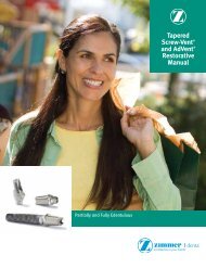
<strong>Restorative</strong> <strong>Manual</strong><strong>Immediate</strong> <strong>Bar</strong> <strong>Fabrication</strong>
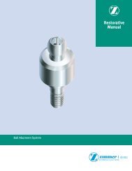
Components for 4.5mmD platform AdVent immediate bar fabricationAdVent Implant TopSurgical Cover Screw[AVSC]and2mmL Implant Extender[AVE]For closed-traytransfer techniqueIndirect Transfer[AVIT/4]includes screw [AVITS]OptionalDirect TransferUse closed-tray transferwith open-tray transferscrew [DHTS]For open-traytransfer techniqueImplant Replica[AVR]Use with closed-trayor open-tray transferprocedureTitanium TemporaryCoping[AVTT]includes screw[AVGCS]Plastic CastableCoping[AVPC]includes screw[AVGCS]5mmL <strong>Bar</strong> GoldCoping[AVGC5]includes screw[AVGCS]3mmL <strong>Bar</strong> GoldCoping[TGC3]includes screw[AVGCS]78 <strong>Immediate</strong> <strong>Bar</strong> <strong>Fabrication</strong>
<strong>Immediate</strong> <strong>Bar</strong> OverdentureOption 1 - Laboratory splinting of barAttaching the transfersAfter threaded implant placement, attach transfers [AVIT/4] with1.25mmD Hex Tool.For implants with a Fixture Mount/Transfer already attached,proceed to next step.Optional: Long impression screws [DHTS] may be used foropen-tray impression technique.Making the impressionBlock out the top of the transfer and any exposed sutures. Placelight body impression material around each transfer and record afull-arch impression with standard body material. Remove theimpression after it fully sets.A silicone putty bite registration and opposing arch impressioncan also be made at this time. This optional procedure will assistthe technician in aligning the bar segments parallel to the planeof occlusion.Unscrew the transfers from implants and forward with theimpression for fabrication of a working cast.Attaching the healing componentsAttach the Surgical Cover Screws [AVSC] using the 1.25mmDHex Tool. Seat the AdVent Extenders [AVE] onto the implantsprior to threading the screws into the implants if an increase intransmucosal height is required.Fabricating the working castConnect the transfer to a corresponding replica [AVR] andinsert the replica/transfer assembly into the impression hole. Adouble-click indicates that the transfers are fully seated. Pour theimpression in die stone to create the working cast. If desired, usesoft tissue material to represent the gingival tissues.Remove the tray from the cast. Unthread the transfer screw[AVITS] with the Hex Tool prior to removing the transfer bodiesfrom the cast.<strong>Immediate</strong> <strong>Bar</strong> <strong>Fabrication</strong> 79
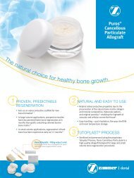
<strong>Immediate</strong> <strong>Bar</strong> OverdentureOption 2 - Intraoral splinting of bar componentsRemoving the healing componentsRemove sutures after the required soft tissue healing period.Remove the Surgical Cover Screw [AVSC] and Extender [AVE] ifplaced, prior to restorative procedures.Attaching the bar componentsSeat the <strong>Bar</strong> Gold Coping on the implant. Use a 1.25mmD HexTool to thread the Coping Screw [AVGCS] into the implant andtighten to 20 Ncm with a calibrated torque wrench.Note: This screw which connects directly to the implant shouldultimately be tightened to 30 Ncm once a satisfactory period forhard tissue healing has occurred.Fig. aFig. bFig. cFig. dFig. eSelecting Gold <strong>Bar</strong> design1) Dolder Gold <strong>Bar</strong> [DGB] is an oval shaped bar 2.3mm in heightand an adjustable 50mm in length (Fig. a). Used in conjunctionwith a matching metal sleeve (Fig. b) and processing spacer(Fig. c) it is designed to allow rotational and vertical movement.2) Hader Gold <strong>Bar</strong> [HGB] is a round shaped bar 1.8mm indiameter and an adjustable 50mm in length (Fig. d). Used inconjunction with a matching yellow plastic rider (Hader Clip)and green processing clip (Fig. e) it is designed to allowrotational movement.The melting range of the prefabricated bars is 1670-1823˚F or910-995 ˚C.Measuring the gold barMeasure gold bar segments to fit between the <strong>Bar</strong> Gold Copings.Design the segments to run parallel to the plane of occlusion aswell as allow sufficient space between the bar and soft tissue toensure easy access for cleansing.<strong>Immediate</strong> <strong>Bar</strong> <strong>Fabrication</strong> 81
<strong>Immediate</strong> <strong>Bar</strong> OverdentureOption2 - Intraoral splinting of bar componentsPlacing the bar sectionsRoughen the surface of the coping to enhance attachment of theluting material. Cut and shape gold bar patterns to fit betweenthe <strong>Bar</strong> Gold Copings. The sections should have an intimate fit soas to reduce the amount of solder space between the adjacentcomponents. The connection between the bar section andcoping should be on a slight taper to increase the surface area ofcontact between the two components improving the strength ofthe connection. The tapering of the coronal circumference of the<strong>Bar</strong> Gold Copings is designed to assist in the planning of taperedconnection between the components.Luting the bar sectionsLute the bar segments [DGB or HGB] and <strong>Bar</strong> Gold Copings[AVGC3 or AVGC5] in place using autopolymerizing burn outresin or equivalent light cure material of choice. Reinforce thejoints by overbulking with additional resin.Note: Place bars in their correct three dimensional orientation toensure correct function of attachments.Loosen the <strong>Bar</strong> Gold Coping Screws with the Hex Tool and thenremove. Carefully remove the bar pattern from the oral cavity.Replace the Surgical Cover Screw [AVSC] and Extender [AVE] ifpreviously attached.The following step can either be performed in the dental office orsent to the dental laboratory.Attaching the Implant ReplicasInsert the Coping Screw [AVGCS] through the top of the copingand gently thread it into the Implant Replica [AVR] with the HexTool. Hold the replica firmly while rotating the screw.Making the stone indexInsert the bar/replica assembly into a soft mix of die stone tocreate an index of the position of the luted framework. This indexwill allow the technician to verify the fit of the framework after thesolder process.Realign the bar sections if necessary and lute them into position.Mold the burn out resin to conform to the slightly oversizedshape of the final solder connection between the components.Proceed to common procedures forprosthesis fabrication on page 8382 <strong>Immediate</strong> <strong>Bar</strong> <strong>Fabrication</strong>
<strong>Immediate</strong> <strong>Bar</strong> OverdentureCommon procedures for bar fabricationPreparing luted bar for solderingCarefully remove the luted bar assembly from the stone die indexor working cast, depending on which method was utilized tocreate the assembly.Place the bar assembly into a slurry of silica-bonded solderinginvestment material ensuring that all metal components arecovered and held in position by the material. Remove excessinvestment material from around the joint to ensure easy accessfor flow of heat and solder. Place the set material into the burnout oven to eliminate the resin material.Soldering of bar segmentsSolder using the direct oven or the open flame techniqueensuring that the temperature to melt the low-fusing solder doesnot exceed 1544˚F or 840˚C.After bench-cooling, the soldered bar is divested. Finish thesoldered joints and lightly polish the bar following standardlaboratory procedures. Take care not to alter the dimensions ofthe bar segments or the <strong>Bar</strong> Gold Coping interface.An option to the above solder technique would be to join thecomponents using laser welding. Temperatures must beregulated to accommodate for the melting range of the gold bars.Attaching the soldered barRemove the Surgical Cover Screws with the Hex Tool. RemoveImplant Extenders [AVE] if previously attached. The sterilized baris seated on the implants in the patients mouth.To determine a passive fit on the implants, a distal gold cylinderincorporated within the bar was attached to its correspondingimplant with a abutment screw [AVGCS]. Finger-tighten the screwwith the 1.25mmD Hex Tool. Visually inspect to verify that nodiscernable gaps are present between the remaining goldcylinders and implants. If a gap is present between the bar andany of the other implants, section the bar appropriately, relute inposition and send back to the laboratory for resoldering.Creating void in the dentureThe patient’s existing or newly created denture can be used.Create adequate clearance in the denture base to accommodatethe bar and implants without contact when the denture is seatedover them and placed into occlusion with the opposing dentition.Techniques for processing the clips in the denture:1) Laboratory: Make a reline impression of the bar attached tothe implants then send bar and denture to the laboratory forrelining of the denture and processing of the clips on theworking cast. (described on following page)2) Intraoral: Pick up the clips off the bar, following traditionalprosthodontic techniques ensuring sufficient block out of the bar.<strong>Immediate</strong> <strong>Bar</strong> <strong>Fabrication</strong> 83
<strong>Immediate</strong> <strong>Bar</strong> OverdentureCommon procedures for bar fabricationMaking the impressionBlock out undercuts beneath the bar with a material dissimilar tothe impression material. Keep the block out area to a minimum toensure that the profile of the bar is transferred accurately to thefinal impression. The defined profile within the impression willassist the technician in retrofitting the bar with attached ImplantReplicas [AVR] into the impression in its correct spatial position.Apply tray adhesive to the under surface of the prepareddenture. Make a full arch impression. Gently close into centricocclusion and simultaneously check that the vertical dimensionof occlusion does not change.Remove the bar, attach healing components to the implants.Send impression and bar to laboratory for processing of denture.Processing the denturePour the impression and attached bar and implant replicas in diestone. Trim then mount the working cast in a reline jig.Follow standard laboratory procedures for relining or rebasingand processing of bar/clip dentures.Use a scalpel to produce a longitudinal slit in the greenprocessing clip. Fold the sides of the clip on each other thenremove. Use the Hader Clip Seating tool, supplied with the bar kit[HGB] to insert the final yellow Hader Clip into the recesscreate by the processing clip.Trimming the dentureThe denture must be processed or trimmed to allow for freerotation of the denture around the yellow clip on the bar whichacts as the fulcrum for the denture. This free rotation will allowthe surrounding soft tissue to assist in carrying load applied tothe prosthesis during the healing process.Return the processed denture and bar to the clinician forfinal delivery.Delivering the final prosthesisSterilize the components prior to insertion in the patients mouth.Secure the bar in place with the <strong>Bar</strong> Gold Coping Screws andtighten to 20 Ncm with a calibrated torque wrench. Reseat thedenture and make final adjustments.Note: This screw which connects directly to the implant shouldultimately be tightened to 30 Ncm once a satisfactory period forhard tissue healing has occurred.Instruct the patient in the use and care of the prosthesis, andprovide oral hygiene instructions. Caution the patient not to usebleach on the prosthesis, which can damage the nylon clip.84 <strong>Immediate</strong> <strong>Bar</strong> <strong>Fabrication</strong>