microSD™ Card Connectors
microSD™ Card Connectors
microSD™ Card Connectors

Create successful ePaper yourself
Turn your PDF publications into a flip-book with our unique Google optimized e-Paper software.
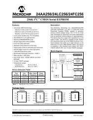
The product informationthis catalog is for reference only. Please request the EngineeringDrawing for the most current and accurate design information.NEWmicroSD <strong>Card</strong> <strong>Connectors</strong>DM3 Series■Features◆ Common to the entire Series1. Extremely small sizeSmall external dimensions and the above-the-board heightmake the connectors the smallest on the market.2. Reverse card insertion protectionUnique card slot design (patented) protects the connectorfrom damage when the card is attempted to be inserted inreverse, allowing it to re-inserted correctly.3. Effective ground and shield configuration4-connection points of the metal cover to the printed circuitboard assures secure connection of the ground circuit andprovides EMI protection.4. Rigid and strong constructionDespite its small size, high-strengths materials used in theconnectors produced a strong and rigid structure.5. <strong>Card</strong> detection switchThe card detection switch is Normally Open◆ DM3D (Push -Pull, manual, withoutejection mechanism)· Partial card insertion hold<strong>Card</strong> will not fall-out even when it is not fully inserted. Fullinsertion and electrical / mechanical connection is confirmedwith a distinct tactile feel.· Accessible termination areasAn inner lead system that can be reworked is used in this design.Contact solder terminations may be inspected and reworked.<strong>Card</strong> insertion-ejectionSeries Image Page◆ DM3AT and DM3BT (Push - Push, withejection mechanism)· <strong>Card</strong> fall-out preventionBuilt-in card tray and the unique push insertion-push ejectionmechanism (patented) prevent accidental card ejection or fallout.Despite its small size the connectors will eject the card to adistance of 4.0 mm, allowing easy hold and removal of the card.· Exposed termination leadsEasy inspection and rework of the solder termination joints.◆ DM3CS (Hinge, Push-Pull, manual, withoutejection mechanism)· Simple and reliable card insertionHinged metal cover provides location and guides the cardduring the insertion / removal. Closing of the cover confirmsthe electrical and mechanical connection with a tactile clicksensation.· Reliable contact with the card contact padsUnique contact design and card slide action will clean thecontact areas of the card.· Accessible termination areasContact solder terminations may be inspected and reworked.Push-PushHinge-manualinsertion/ejectionPush-Pullmanual insertion/ejectionDM3ATDM3BTDM3CSDM3D2~45~67~89~102010.6w1
The product informationthis catalog is for reference only. Please request the EngineeringDrawing for the most current and accurate design information.DM3 Series●microSD <strong>Card</strong> <strong>Connectors</strong>■Specifications(DM3 Series)RatingsCurrent rating: 0.5AVoltage rating: 125V ACOperating temperature range: -25ç to +85ç (Note 1)Storage temperature range : -40ç to +85ç (Note 2)Operating humidity range: RH 95% max.(No condensation)Item Specification Conditions1. Insulation resistance2. Withstanding voltage3. Contact resistance1000 Mø min. (Initial value)No flashover or insulation breakdown100mø max. (Initial value)Measure at 500 V DC500 V AC / 1 minute1mA4. Vibration5. Humidity6. Temperature cycle7. DurabilityNo electrical discontinuity of 100 ns or longerNo damage, cracks or parts dislocation.Contact resistance: 40 mø max. (change from initial value)Insulation resistance: 100 Mø min.No damage, cracks or parts dislocation.Contact resistance: 40 mø max. (change from initial value)Insulation resistance: 100 Mø min.No damage, cracks or parts dislocation.Contact resistance: 40 mø max. (change from initial value)Frequency: 10 to 55 Hz, single amplitude of 0.75 mm,3 directions for 2 hours96 hours at of 40 ± 2ç, and humidity of 90 to 95%-55ç ➝ 5 to 35ç ➝85ç ➝ 5 to 35çTimes: 30 min. ➝ 5 min. ➝ 30 min. ➝ 5 min.5 cycles10,000 cycles, 400 to 600 cycles per hour (DM3AT, DM3B)5,000 cycles, 400 to 600 cycles per hour (DM3C, DM3D)8. Resistance tosoldering heatNo deformation of components affecting performance.Note 1: Includes temperature rise caused by current flow.Note 2. The term "storage" refers to products stored for long period prior to mounting and use.■Materials and FinishesDM3AT, DM3BTPart Material FinishInsulatorLCPColor: BlackReflow : At the recommended temperature profileManual soldering : 350ç for 3 secondsRemarksUL94V-0ContactsCopper alloyContact area: Gold platedLead area: Gold plated-------------------Guide coverStainless steelCopper alloy(DM3AT)(DM3BT)Lead area: Gold plated-------------------Other componentsStainless steelPiano wire(DM3AT, DM3BT)(DM3BT)-------------------Nickel plated-------------------DM3CS, DM3DPart Material FinishInsulatorLCPColor: BlackRemarksUL94V-0ContactsCopper alloyContact area: Gold platedLead area: Gold plated-------------------Guide coverStainless steelTin plated-------------------■Ordering informationDM3 AT – SF – PEJM51 2 341 Series name: DM32 Connector type : AT Push-Push (ejection mechanism), Top board mounting (Standard)BT Push-Push (ejection mechanism), Bottom board mounting (Reverse)CS Hinge, Push-Pull (no ejection mechanism), Top board mounting (Standard)D Push-Pull (no ejection mechanism), Top board mounting (Standard)Number of contacts : 834Termination type : SF Right-angle SMT(Standard)DSF Right-angle SMT(Reverse)<strong>Card</strong> ejection code : PEJM5, PEJS(Push insert/push eject)None: Manual cardinsertion/ejection2
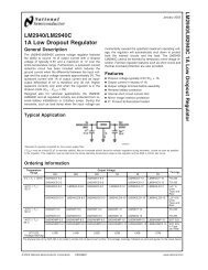
The product informationthis catalog is for reference only. Please request the EngineeringDrawing for the most current and accurate design information.DM3 Series●microSD <strong>Card</strong> <strong>Connectors</strong>■DM3AT Push-Push (ejection mechanism), Top board mounting (Standard)#5(CLK)#6(VSS)#7(DAT0)#8(DAT1)#4(VDD)#3(CMD)#2(CD/DAT3)#1(DAT2)2CARD DETECTIONSWITCH(B)13.85(7.35)(3.2)1.68Part numberCL No.DM3AT-SF-PEJM5 609-0031-0215.95CARD DETECTIONSWITCH(A)(15)15.95(16.75):CARD OVER STROKE POSITION(17.55):CARD LOCK POSITION(21.55):CARD EJECT POSITION(0.8)microSD CARD(5.5)LC(11)1All dimensions: mm■Recommended PCB mounting pattern2.90.150.70.15MIN1.210MIN9.25MAX8.657.71.55P=1.10.711.2Note1C L indicates the center line of themicroSD card slot.14.0513.3MIN9.97.9MIN5.7MAX3.738.9MIN8.2MIN0.534.4MAX6MIN14.1MAX14.515.12<strong>Card</strong> detection switchWithout the cardOpen<strong>Card</strong> insertedClosed 3(A) (B) (A) (B)2.80.8119.10.15(3.2)2.73.25C0.151.31.93No conductive traces.All dimensions: mm● Example of applicationsDM3AT-SF-PEJM5Portable device3
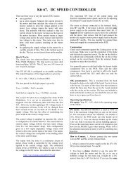
The product informationthis catalog is for reference only. Please request the EngineeringDrawing for the most current and accurate design information.DM3 Series●microSD <strong>Card</strong> <strong>Connectors</strong>■Packaging Specifications● Embossed carrier tape dimensions (1,500 pieces per reel)Ø1.520(16.35)14.21.75P=42UNREELING DIRECTION(3.2)3228.4All dimensions: mm● Reel Dimensions32.4CIRCLETRAILERPORTION EQUIPPEDWITH COMPONENTSLEADER(400mm MIN)Ø80Ø380STARTENDOVALEMPTY(160mm MIN)EMBOSSED CARRIER TAPEEMPTY(100mm MIN)TOP COVER TAPE4
The product informationthis catalog is for reference only. Please request the EngineeringDrawing for the most current and accurate design information.DM3 Series●microSD <strong>Card</strong> <strong>Connectors</strong>■DM3BT, Push-Push (ejection mechanism), Bottom board mounting (Reverse)#4(VDD)#3(CMD)#2(CD/DAT3)#1(DAT2)#5(CLK)#6(VSS)#7(DAT0)#8(DAT1)2.38MAX1.83(3.2)13.85(6.5)CARD DETECTIONSWITCH(B)2Part numberCL No.DM3BT-DSF-PEJS 609-0029-9(0.55)3(21.55)CARD EJECT POSITION(17.55)CARD LOCK POSITION(16.75)CARD OVER STROKE POSITION16.0515.95(15)2.7MAX6.7MAX315.115.45CARD DETECTIONSWITCH(A)321CL (5.5)microSD CARD(11)■Recommended PCB mounting pattern2.9±0.15All dimensions: mm14.751.414.310.0510MIN9.25MAX8.657.71.9P=1.10.740.70.20.35MIN1.23.57.7MIN9.713.3Note12C L indicates the center line of themicroSD card slot.<strong>Card</strong> detection switchWithout the cardOpen<strong>Card</strong> insertedClosed1.91.50.150.53.05(3.2) 18.91.20.83.234(A) (B) (A) (B)Oblique-hatched area is projectionof contact.No conductive traces.All dimensions: mm● Example of applicationsDM3BT-DSF-PEJSPortable device5
The product informationthis catalog is for reference only. Please request the EngineeringDrawing for the most current and accurate design information.DM3 Series●microSD <strong>Card</strong> <strong>Connectors</strong>■Packaging Specifications● Embossed carrier tape dimensions (1,200pieces per reel)P42UNREELING DIRECTION(3.75)3228.41.75Ø1.520(16.35)14.2All dimensions: mm● Reel Dimensions32.4CIRCLETRAILERPORTION EQUIPPEDWITH COMPONENTSLEADER(400mm MIN)Ø80Ø380STARTENDOVALEMPTY(160mm MIN)EMBOSSED CARRIER TAPEEMPTY(100mm MIN)TOP COVER TAPE6
The product informationthis catalog is for reference only. Please request the EngineeringDrawing for the most current and accurate design information.DM3 Series●microSD <strong>Card</strong> <strong>Connectors</strong>■DM3CS, Hinge, Push -Pull (no ejection mechanism), Top board mounting (Standard)CARD DETECTION SWITCH2(6.9)13.8(0.2) 1.83(15.45):LOCK POSITION14.11213.90.1Part numberCL No.DM3CS-SF 609-0032-3(5.5) (11)1microSD CARD(0.93)(1.78)■Recommended PCB mounting pattern8(DAT1)7(DAT0)6(VSS)5(CLK)1(DAT2)2(CD/DAT3)3(CMD)4(VDD)All dimensions: mm12.95.4MIN7.8MAX2.62.9MAX2.7(13.8)8.25MIN6.31.42.70.55MIN1.651.21.21.42.67.8MAX2<strong>Card</strong> detection switch10.1MIN9.5MAX3 34.1MIN3.5MAXWithout the cardOpen<strong>Card</strong> insertedClosed3 GND(1)GND(1)GND(2)GND(2)GND(3)GND(3)GND(4)GND(4)1 0.7P1.1(3.2)3 No conductive traces.7.71.5 9.3 2.8All dimensions: mm12.412.9(14.1)14.4Note1C L indicates the center line of themicroSD card slot.● Example of Use applicationsDM3CS-SF (shown open forcard insertion)DM3CS-SF (shown closed,with card inserted)Portable device7
The product informationthis catalog is for reference only. Please request the EngineeringDrawing for the most current and accurate design information.DM3 Series●microSD <strong>Card</strong> <strong>Connectors</strong>■Packaging Specifications● Embossed carrier tape dimensions (1,300pieces per reel)Ø1.520(3.4)14.21.75P42UNREELING DIRECTION3228.4All dimensions: mm● Reel Dimensions32.4CIRCLETRAILERPORTION EQUIPPEDWITH COMPONENTSLEADER(400mm MIN)Ø80Ø380STARTENDOVALEMPTY(160mm MIN)EMBOSSED CARRIER TAPEEMPTY(100mm MIN)TOP COVER TAPE8
The product informationthis catalog is for reference only. Please request the EngineeringDrawing for the most current and accurate design information.DM3 Series●microSD <strong>Card</strong> <strong>Connectors</strong>■DM3D, Push-Pull (no ejection mechanism), Top board mounting (Standard)2<strong>Card</strong> DetectionSwitch (B)1.5511.95(6)<strong>Card</strong> DetectionSwitch (A)23.351(15.8):CARD FULLY INSERTED11.459.65(15)11.450.92.7Part numberCL No.DM3D-SF 609-0025-8(0.7)(4.5)(5.5)(11)<strong>Card</strong>CentermicroSD <strong>Card</strong>■Recommended PCB mounting pattern8(DAT1)7(DAT0)6(VSS)5(CLK)1(DAT2)2(CD/DAT3)3(CMD)4(VDD)All dimensions: mm0.4MIN8.1MIN5.05MIN2.55MAX311Note1C L indicates the center line of themicroSD card slot.10.2MIN8.358.2MAX6.851.56MIN4MAX0.8( 4.5 )0.81.47.59.1510.71.52<strong>Card</strong> detection switchWithout the cardOpen<strong>Card</strong> insertedClosed1.51.850.551.17.7C L 19.410.91.753(A) (B) (A) (B)No conductive traces.All dimensions: mm● Example of applicationsDM3D-SFPortable device9
The product informationthis catalog is for reference only. Please request the EngineeringDrawing for the most current and accurate design information.DM3 Series●microSD <strong>Card</strong> <strong>Connectors</strong>■Packaging Specifications● Embossed carrier tape dimensions (2,000pieces per reel)2Unreeling directionUnreeling direction24.4End sectionBlank section(160mm min.)Mounting sectionLead section (400mm min.)Blank section(100mm min.)Ø80Ø3802422.2511.5 1.75Ø1.5P=416( 11.85 )All dimensions: mm● Reel DimensionsEmbossed carrier tapeTop cover tape10
The product informationthis catalog is for reference only. Please request the EngineeringDrawing for the most current and accurate design information.DM3 Series●microSD <strong>Card</strong> <strong>Connectors</strong>■Recommended temperature profileTemperature(ç)25020015010050150ç230ç min.200ç90 to 120 secondsPreheatingTime (Seconds)Peak:250ç MAX50secondsSolderingHRS test conditionSolder method :Reflow, IR/hot airEnvironment :Room airSolder composition :Paste, 96.5%Sn/3.0%Ag/0.5%Cu(Senju Metal Industry, Co., Ltd.'sPart Number:M705-GRN360-K2-V)Test board :Glass epoxy 60mm∞100mm∞1.0mm thickMetal mask :0.12mm thickNumber of reflow cycles : 2cycles max.The temperature profiles shown are based on the aboveconditions.In individual applications the actual temperature may vary,depending on solder paste type, volume / thickness and boardsize / thickness. Consult your solder paste and equipmentmanufacturer for specific recommendations.■Precautions1. Do not immerse or clean the entire connector with cleaning solutions as this may affect proper operation of theejection mechanism and electrical performance of the connector2. Do not apply excessive force to the connector when handling or after installation on the PC board.3. The connectors will reliably connect and operate with the correctly inserted microSD TM cards.Follow the correct insertion / ejection procedure for the specific connector in use.Attempts of incorrect insertion of the card may cause damage to the connector or the card.4. The connector must be correctly mounted on the PC board before the card can be inserted. Do not insert the card inthe un-mounted connector.5. Mounting on the Flexible Printed Circuit (FPC)To assure correct performance it is recommended that a flat reinforcement plate 0.3 mm min. thick be used underthe FPC.6. Small visible residual manufacturing fluids or tooling marks do not affect connector's performance.7. Repeated insertions and removal of the cards may leave some marks on the card itself. This will have no affect onthe connector performance.● Refer to applicable Operation Manual listed below for additional precautions.SeriesDM3AT SeriesDM3BT SeriesDM3CS SeriesDM3D SeriesOperation Manual NumberETAD-F0345ETAD-F0324ETAD-F0335ETAD-F035311