

Body Forms - PRO-QUIP
Body Forms - PRO-QUIP
Body Forms - PRO-QUIP

Create successful ePaper yourself
Turn your PDF publications into a flip-book with our unique Google optimized e-Paper software.
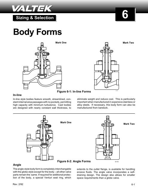
Mark OneMark TwoE0143Three-wayThree-way bodies are used for either combining ordiverting services. Due to Valtek’s excellent parts interchangeability,a standard globe valve easily converts toFigure 6-3: Three-way <strong>Forms</strong>three-way service with the addition of a three-wayadaptor, upper seat ring, two gaskets, a three-wayplug, and bonnet flange bolting.Mark TwoMark ElevenE0149OffsetWhen inlet and outlet piping can be offset, this design isthe simplest, least expensive barstock style. A MarkEleven works best in self cleaning applications. Other6-2Figure 6-4: Offset <strong>Forms</strong>E0147than the body, the offset design is completely interchangeablewith the standard Valtek globe valve.
Mark One-XMark OneE0146Figure 6-5: Expanded Outlet FormFigure 6-6: Steam Jacketed FormExpanded OutletThe expanded outlet valve, such as a Mark One-X,permits the installation of a small valve in a larger linewithout using line reducers or expanders. The valve isa standard in-line globe valve, except for the bodywhich incorporates expanded outlets. Therefore, allparts – except the body – are interchangeable with theMark One. Because line expanders and reducers arenot used, field installation expenses are reduced. Theexpanded outlet valve is less costly than a full-sizeMark One with the same size end connections.Steam JacketedSteam jackets are used to heat the fluid passing throughthe control valve. The steam jacketed valve body usesa standard globe-style body with oversized, blindflanges for a full jacket or standard flanges for a partialjacket. The jacket usually is rated for 150 psi and comesequipped with 3 /4-inch NPT supply and drain connection.END CONNECTIONSStandard globe valve bodies have a raised face hub foreither separable or integral flanges. Separable flangesare highly recommended because less expensive carbonsteel separable flanges can be specified for use onalloy valves as a cost-saving measure. (Stainless steelflanges may be required with a high temperature/pressureservice. See factory for specific limitations.) Separableflange valves are also easier to install with themating piping because the flanges can be rotated to fitthe line flange hole pattern. To achieve better sealingwith the mating piping, the flange face is machined withgroove serrations.Integral flanges can also be provided with a flat face,RTJ (ring-type joint), or tongue and groove connections– depending upon the user’s requirements.NPT (National Pipe Threads) connections are providedfor small valves (2-inch and smaller). They are designedwith a female NPT to mate with piping usingmale NPT threads, and are usually used in pressuresless than ANSI Class 600. Because of the threadedconnection, these connections are limited to non-corrosiveservices. See Figure 6-9.Socketweld connections are usually used in high pressure,high temperature fluids in sizes 2-inch andsmaller. The connection uses a bore in the body endwhich mates with the corresponding piping. A weld isthen applied between the body face and the pipe. SeeFigure 6-10.For high pressure, high temperature services above 2-inch, buttweld connections are used. Buttwelds arecommon to steam and water services in power plants.Usually, the buttweld angle machined into the bodymatches the angle machined into the piping. A fullpenetration weld is then applied to the butt joint. Thematerial in the body and piping should be compatible toensure proper welding. See Figure 6-11.6-3
Figure 6-9:Threaded End Connection (NPT)Figure 6-10:Socketweld End ConnectionSeparable Flange MaterialInterchangeable separable flanges are standard forMark One valve bodies through 4 inch in Class 150, 300and 600 ANSI ratings, and for 6 and 8 inch bodies inClass 300 and 600. With separable end flanges, aClass 600 body can be adapted for Class 150, 300, or600 service by simply changing to the proper endflanges.Separable flanges are usually furnished in carbon steelfor maximum cost savings, although other alloys can bespecified if the atmospheric conditions or the temperaturewarrants it.NOTE: Carbon steel bodies, carbon steel end andbonnet flanges should not be used when temperaturesare 800 degrees Fahrenheit or greater.Figure 6-11: Buttweld End ConnectionEnd Flange DimensionsTables 6-III thru 6-VIII provide standard dimensions forValtek end flanges (both separable and integral) accordingto ANSI B16.5, 1988.Table 6-II: End Flange Material<strong>Body</strong> Material Size Class Std. Flange Material Opt. Flange MaterialCarbon Steel 1/2 - 4 150 - 600 Carbon Stainless6 - 8 300 - 600 Steel (a) Steel (b)Stainless Steel 1/2 - 4 150 - 600 Carbon Stainless6 - 8 300 - 600 Steel (a) Steel (b)Alloys 1/2 - 4 150 - 600 Carbon Stainless6 - 8 300 - 600 Steel (a) Steel (b)(c)(a) Carbon steel end flanges with zinc plated steel half rings can be used in most all corrosive applications since the flanges are not wetted bythe fluid.(b) Stainless steel flanges and half-rings are usually only necessary when atmospheric conditions or temperature limitations require stainlesssteel. Carbon steel will usually suffice.(c) Optional alloys are also available.6-5
Table 6-III: Class 150 Flange Dimensions1 2 3 4 5 6Nominal OutsideDrillingPipe Diameter of Diameter of Diameter of Number DiameterSize Flange O Bolt Circle Bolts Holes of Bolts of Bolts1/2 3.50 2.38 0.62 4 1/23/4 3.88 2.75 0.62 4 1/21 4.25 3.12 0.62 4 1/21 1 /4 4.62 3.50 0.62 4 1/21 1 /2 5.00 3.88 0.62 4 1/22 6.00 4.75 0.75 4 5/82 1 /2 7.00 5.50 0.75 4 5/83 7.50 6.00 0.75 4 5/83 1 /2 8.50 7.00 0.75 8 5/84 9.00 7.50 0.75 8 5/85 10.00 8.50 0.88 8 3/46 11.00 9.50 0.88 8 3/48 13.50 11.75 0.88 8 3/410 16.00 14.25 1.00 12 7/812 19.00 17.00 1.00 12 7/814 21.00 18.75 1.12 12 116 23.50 21.25 1.12 16 118 25.00 22.75 1.25 16 1 1 /820 27.50 25.00 1.25 20 1 1 /824 32.00 29.50 1.38 20 1 1 /4Table 6-IV: Class 300 Flange Dimensions1 2 3 4 5 6Nominal OutsideDrillingPipe Diameter Diameter Diameter Number DiameterSize of Flange of Bolt of Bolts of Bolts of BoltsO Circle Holes1/2 3.75 2.62 0.62 4 1/23/4 4.62 3.25 0.75 4 5/81 4.88 3.50 0.75 4 5/81 1 /4 5.25 3.88 0.75 4 5/81 1 /2 6.12 4.50 0.88 4 3/42 6.50 5.00 0.75 8 5/82 1 /2 7.50 5.88 0.88 8 3/43 8.25 6.62 0.88 8 3/43 1 /2 9.00 7.25 0.88 8 3/44 10.00 7.88 0.88 8 3/45 11.00 9.25 0.88 8 3/46 12.50 10.62 0.88 12 3/48 15.00 13.00 1.00 12 7/810 17.50 15.25 1.12 16 112 20.50 17.75 1.25 16 1 1 /814 23.00 20.25 1.25 20 1 1 /816 25.50 22.50 1.38 20 1 1 /418 28.00 24.75 1.38 24 1 1 /420 30.50 27.00 1.38 24 1 1 /424 36.00 32.00 1.62 24 1 1 /26-6(Reprinted from ANSI B16.5, 1988 with permission from the American Society of Mechanical Engineers)
Table 6-V: Class 600 Flange Dimensions1 2 3 4 5 6Nominal OutsideDrillingPipe Diameter Diameter Diameter Number DiameterSize of Flange of Bolt of Bolt of Bolts of BoltsO Circle Holes1/2 3.75 2.62 0.62 4 1/23/4 4.62 3.25 0.75 4 5/81 4.88 3.50 0.75 4 5/81 1 /4 5.25 3.88 0.75 4 5/81 1 /2 6.12 4.50 0.88 4 3/42 6.50 5.00 0.75 8 5/82 1 /2 7.50 5.88 0.88 8 3/43 8.25 6.62 0.88 8 3/43 1 /2 9.00 7.25 1.00 8 7/84 10.75 8.50 1.00 8 7/85 13.00 10.50 1.12 8 16 14.00 11.50 1.12 12 18 16.50 13.75 1.25 12 1 1 /810 20.00 17.00 1.38 16 1 1 /412 22.00 19.25 1.38 20 1 1 /414 23.75 20.75 1.50 20 1 3 /816 27.00 23.75 1.62 20 1 1 /218 29.25 25.75 1.75 20 1 5 /820 32.00 28.50 1.75 24 1 5 /824 37.00 33.00 2.00 24 1 7 /8Table 6-VII: Class 1500 Flange Dimensions1 2 3 4 5 6Nominal OutsideDrillingPipe Diameter Diameter Diameter Number DiameterSize of Flange of Bolt of Bolt of Bolts of BoltsO Circle Holes1/2 4.75 3.25 0.88 4 3/43/4 5.12 3.50 0.88 4 3/41 5.88 4.00 1.00 4 7/81 1 /4 6.25 4.38 1.00 4 7/81 1 /2 7.00 4.88 1.12 4 12 8.50 6.50 1.00 8 7/82 1 /2 9.62 7.50 1.12 8 13 10.50 8.00 1.25 8 1 1 /84 12.25 9.50 1.38 8 1 1 /45 14.75 11.50 1.62 8 1 1 /26 15.50 12.50 1.50 12 1 3 /88 19.00 15.50 1.75 12 1 5 /810 23.00 19.00 2.00 12 1 7 /812 26.50 22.50 2.12 16 214 29.50 25.00 2.38 16 2 1 /416 32.50 27.75 2.62 16 2 1 /218 36.00 30.50 2.88 16 2 3 /420 38.75 32.75 3.12 16 324 46.00 39.00 3.62 16 3 1 /2Table 6-VI: Class 900 Flange Dimensions1 2 3 4 5 6Nominal OutsideDrillingPipe Diameter Diameter Diameter Number DiameterSize of Flange of Bolt of Bolt of Bolts of BoltsO Circle Holes1/23/411 1 /4 Use Class 1500 dimensions in these sizes1 1 /222 1 /23 9.50 7.50 1.00 8 7/84 11.50 9.25 1.25 8 1 1 /85 13.75 11.00 1.38 8 1 1 /46 15.00 12.50 1.25 12 1 1 /88 18.50 15.50 1.50 12 1 3 /810 21.50 18.50 1.50 16 1 3 /812 24.00 21.00 1.50 20 1 3 /8Table 6-VII: Class 1500 Flange Dimensions1 2 3 4 5 6Nominal OutsideDrillingPipe Diameter Diameter Diameter Number DiameterSize of Flange of Bolt of Bolt of Bolts of BoltsO Circle Holes1/2 5.25 3.50 0.88 4 3/43/4 5.50 3.75 0.88 4 3/41 6.25 4.25 1.00 4 7/81 1 /4 7.25 5.12 1.12 4 11 1 /2 8.00 5.75 1.25 4 1 1 /82 9.25 6.75 1.12 8 12 1 /2 10.50 7.75 1.25 8 1 1 /83 12.00 9.00 1.38 8 1 1 /44 14.00 10.75 1.62 8 1 1 /25 16.50 12.75 1.88 8 1 3 /46 19.00 14.50 2.12 8 28 21.75 17.25 2.12 12 210 26.50 21.25 2.62 12 2 1 /212 30.00 24.38 2.88 12 2 3 /414 25.25 22.00 1.62 20 1 1 /216 27.75 24.25 1.75 20 1 5 /818 31.00 27.00 2.00 20 1 7 /820 33.75 29.50 2.12 20 224 41.00 35.50 2.62 20 2 1 /2All dimensions are in inches6-7
F F FSeparable Integral RTJFlange Flange FlangeValveSize(inches)Table 6-IX: Dimension F (inches) – Valve Face to Back of FlangeANSI Class150 300 600 900 1500 2500SEP INT RTJ SEP INT RTJ SEP INT RTJ INT RTJ INT RTJ INT RTJ1/2 .88 .44 .94 .56 .78 .94 .81 .78 1.12 1.12 1.12 1.12 1.44 1.443/4 .91 .50 1.16 .62 .88 1.16 .88 .88 1.25 1.25 1.25 1.25 1.44 1.441 .91 .56 .81 1.16 .69 .94 1.16 .94 .94 1.38 1.38 1.38 1.38 1.62 1.621 1 /2 1.03 .69 .94 1.28 .81 1.06 1.28 1.12 1.12 1.50 1.50 1.50 1.50 2.00 2.062 1.06 .75 1.00 1.31 .88 1.19 1.44 1.25 1.31 1.75 1.81 1.75 1.81 2.25 2.313 1.38 .94 1.19 1.62 1.12 1.44 1.75 1.50 1.56 1.75 1.81 2.12 2.19 2.88 3.004 1.44 .94 1.19 1.69 1.25 1.56 2.06 1.75 1.81 2.00 2.06 2.38 2.44 3.25 3.446 1.00 1.25 1.82 1.44 1.75 2.79 2.12 2.19 2.44 2.50 3.50 3.62 4.50 4.758 1.12 1.38 2.11 1.62 1.94 3.14 2.44 2.50 2.75 2.81 3.88 4.06 5.25 5.5610 1.19 1.44 1.88 2.19 2.75 2.81 3.00 3.06 4.50 4.69 6.75 7.1912 1.25 1.50 2.00 2.31 2.88 2.94 3.38 3.44 5.12 5.44 7.50 7.9414 1.38 1.63 2.12 2.44 3.00 3.06 3.62 3.81 5.50 5.8816 1.44 1.69 2.25 2.56 3.25 3.31 3.75 3.94 6.00 6.4418 1.56 1.81 2.38 2.69 3.50 3.56 4.25 4.50 6.62 7.0620 1.69 1.94 2.50 2.88 3.75 3.88 4.50 4.75 7.25 7.6924 1.88 2.12 2.75 3.19 4.25 4.38 5.75 6.12 8.25 8.81Notes:1. Integral and RTJ flange information from ANSI B16.5.2. Separable flanges are not available in ANSI Classes 900, 1500 or 2500, valve sizes 10-inch and larger;or in valve sizes 6 and 8-inch in Class 150.6-8


