Appendix B - Watercare
Appendix B - Watercare Appendix B - Watercare
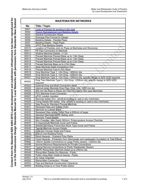
Watercare Services LimitedWater and Wastewater Code of Practicefor Land Development and Subdivision_____________________________________________________________________________________________Content from the Standard NZS 4404:2010 Land development and subdivision infrastructure has been reproduced foruse in the Infrastructure Design Standards Manual for Local Networks with permission form Standards New ZealandWASTEWATER NETWORKSNo Title / TopicWW1 Code of Practice for working in the roadWW2 Trench Reinstatement and Bedding DetailsWW3 General Construction NotesWW4 Drainage Plan Format for DesignWW6 Bedding Details - Flexible PipesWW7 Bedding Details - Rigid PipesWW8 uPVC Pipe Bedding DetailsWW10 Location of Flexible Joint on Pipes at Manholes and StructuresWW11 PE Pipe Connection to ManholeWW12 Shallow Manhole Details ,2m Drop, >250mm dia, specific design to NZS 4229requiredWW23 External Drop and Multi Connection detailWW24 Internal (extg) Manhole Drop Pipe, Drop
- Page 2 and 3: Watercare Services LimitedWater and
<strong>Watercare</strong> Services LimitedWater and Wastewater Code of Practicefor Land Development and Subdivision_____________________________________________________________________________________________Content from the Standard NZS 4404:2010 Land development and subdivision infrastructure has been reproduced foruse in the Infrastructure Design Standards Manual for Local Networks with permission form Standards New ZealandWASTEWATER NETWORKSNo Title / TopicWW1 Code of Practice for working in the roadWW2 Trench Reinstatement and Bedding DetailsWW3 General Construction NotesWW4 Drainage Plan Format for DesignWW6 Bedding Details - Flexible PipesWW7 Bedding Details - Rigid PipesWW8 uPVC Pipe Bedding DetailsWW10 Location of Flexible Joint on Pipes at Manholes and StructuresWW11 PE Pipe Connection to ManholeWW12 Shallow Manhole Details ,2m Drop, >250mm dia, specific design to NZS 4229requiredWW23 External Drop and Multi Connection detailWW24 Internal (extg) Manhole Drop Pipe, Drop
<strong>Watercare</strong> Services LimitedWater and Wastewater Code of Practicefor Land Development and Subdivision_____________________________________________________________________________________________Content from the Standard NZS 4404:2010 Land development and subdivision infrastructure has been reproduced foruse in the Infrastructure Design Standards Manual for Local Networks with permission form Standards New ZealandWW55WW57WW58NoWS1WS2WS3WS5WS6WS7WS8WS9WS10WS11WS12WS13WS14WS15WS16WS17WS18WS19WS20WS21WS22WS23WS24WS25WS26WS27WS28WS29WS30WS31WS32WS33WS34WS36WS37WS38WS39WS40WS42WS44WS45WS46WS47Pipe & MH Location Influence Zones and ClearancesPrivate' Reflux Valve ChamberAnchor and Anti-Scour BlockWATER NETWORKSTitle / TopicCode of Practice for working in the roadTrench Reinstatement and Bedding DetailsGeneral Construction NotesTypical Watermain Intersection DetailsRoad Crossing Details and Principal Main to Rider Main ConnectionsPressure Zone Boundary DetailsValve and Hydrant MarkingsHDPE/Polyprolylene Water Meter and Valve BoxesCast Iron Valve BoxesHot Dipped Galvanised Containment Device BoxesHot Dipped Galvinised Water Meter BoxService Connection DetailSubdivision Connection DetailAnchor Block Details for 90 o and 45 o CI/DI BendsAnchor Block Details for 22 1/2 o and 11 1/4 o CI/DI BendsAnchor Block Details for Reducers and Vertical BendsFire System ConnectionContainment Devices 50 mm RPZContainment Devices 50 mm Pipework and Backfow for 40 mm meterFire System with Domestic Connection (Insde Boundary)Standard Service Connection InstallationWater Meter BankFire System with Domestic Connection (Outside the Boundary)Combined Domestic and Fire Supply - 40mm and aboveFire Supply Leakage DetectionWater Supply Connections for Residential DevelopmentFire Supply ConnectionHydrant Details (Non-PE Mains)Hydrant Details (PE Mains)Sluice Valve Details (Non-PE Mains)Sluice Valve Details (PE Mains)Air Release Valve and Chamber DetailsTypical Rider Main Connection to Principal MainExample of Connection to Arterial MainFlange Connection Detail (PE Mains)Ducting for Private WaysGibault Rider Main ConnectionTapping Band Rider Main ConnectionWater Meter Banks Typical LayoutCast Iron Hydrant BoxCast Iron Valve BoxReinforced Concrete Hydrant Box SurroundWooden Water Meter Box with Hinged Lid_____________________________________________________________________________________________Version 1.5July 2013 This is a controlled electronic document and is uncontrolled on printing 2 of 2
GENERAL CONSTRUCTION NOTESSTANDARDS RELATING TO WORKSAll works are to be carried out to the requirements of the Health and Safety inEmployment Act 1992.All works to be carried out will be of the highest tradesman like standard.MANUFACTURERS’ SPECIFICATIONSAll materials shall be used and installed as per manufacturers’ specifications.CONCRETEAll on-site concrete is to be 17.5 MPa unless otherwise stated.WELDING AND FIXINGSAll steelwork is to be workshop fabricated. No on-site welding will be accepted.All steelwork is to be hot dip galvanised to AS/NZS 4680:2006.All metal nuts, bolts and washers are to be of stainless steel.REINFORCING STEELAll reinforcing steel is to be deformed mild steel, unless otherwise specified.All steel is to be centrally placed with a minimum cover of 60 mm for principal steeland 50 mm elsewhere.All radii to be cold formed.WORKS REQUIRING EPOXYAny stainless steel fixings that are epoxied in place are to be supplied from themanufacturer “NOT OILED”.All metal fixings and/or stainless steel to be epoxied will use EPCON C6 epoxy orsimilar, to the Engineer’s recommendation.GENERALCONSTRUCTION NOTESSCALE:N.T.S.ISSUE DATE: NOVEMBER 2012BASED ON: METROWATER 12908/200WSL PLAN No: WW 3
GENERAL CONSTRUCTION NOTESSTANDARDS RELATING TO WORKSAll works are to be carried out to the requirements of the Health and Safety inEmployment Act 1992.All works to be carried out will be of the highest tradesman like standard.MANUFACTURERS’ SPECIFICATIONSAll materials shall be used and installed as per manufacturers’ specifications.CONCRETEAll on-site concrete is to be 17.5 MPa unless otherwise stated.WELDING AND FIXINGSAll steelwork is to be workshop fabricated. No on-site welding will be accepted.All steelwork is to be hot dip galvanised to AS/NZS 4680:2006.All metal nuts, bolts and washers are to be of stainless steel.REINFORCING STEELAll reinforcing steel is to be deformed mild steel, unless otherwise specified.All steel is to be centrally placed with a minimum cover of 60 mm for principal steeland 50 mm elsewhere.All radii to be cold formed.WORKS REQUIRING EPOXYAny stainless steel fixings that are epoxied in place are to be supplied from themanufacturer “NOT OILED”.All metal fixings and/or stainless steel to be epoxied will use EPCON C6 epoxy orsimilar, to the Engineer’s recommendation.GENERALCONSTRUCTION NOTESSCALE:N.T.S.ISSUE DATE: NOVEMBER 2012BASED ON: METROWATER 12908/200WSL PLAN No: WW 3
WMHEAVYDUTY
Manukau Water


